This article covers the following learning outcome: outline the controls available to maintain safety critical equipment.
- Emergency Shutdown (ESD) equipment and systems
- Emergency Shutdown (ESD) systems
- Components of an emergency shutdown system
- Level of shutdown
- Safety Integrity Levels (SIL) for instrumentation
- Safety Instrumented Systems (SIS)
- Safety Integrity Level (SIL)
- Procedures for bypassing Emergency Shutdown (ESD) systems
- Bypassing ESD
- Blow down facilities, flare types
- Types of flares
- Closed and open drain headers, sewers, interceptors
- Drainage
- REVISION QUESTIONS FOR ELEMENT 3 CONTINUED
Emergency Shutdown (ESD) equipment and systems
Emergency Shutdown (ESD) systems
The petrochemical industry, both onshore and offshore, processes large quantities of hazardous material within a contained environment. Consequently, it needs to have in place systems which will either prevent loss of containment from happening or mitigate the consequences of such an event if it does happen. These systems are known as Emergency Shutdown (ESD) systems and take the form of various components, each of which is designed to deal with a particular scenario and bring it under control in a safe and effective manner.
Emergency shutdown systems – functionality
All emergency shutdown systems need to have a high Safety Integrity Level (SIL). Safety integrity levels are a measure of the dependability of a system or component. We shall be looking at safety integrity levels in more detail, later in this article.
A typical emergency shutdown system is made up of:
- Various sensors to detect any fire or escape of gas or vapour;
- Valves and trip relays to isolate sections of the process;
- A system logic for processing any incoming signals;
- An alarm system to warn operators and control room staff of a potential adverse occurrence.
The system processes the incoming signals and activates output commands in accordance with the cause and effect chart which will have previously been defined for that particular refinery or installation.
Emergency shutdown systems – typical actions
- Shutdown of part systems and equipment;
- Isolate hydrocarbon inventories;
- Isolate electrical equipment;
- Stop hydrocarbon flow;
- Depressurize/blow down;
- Activate fire-fighting controls (water deluge, inert gas, foam system, water mist);
- Activate emergency ventilation control;
- Close watertight doors and fire doors.
As we have just mentioned, the emergency shutdown system operates using a cause and effect strategy. This strategy allows the system to apply an appropriate response to a given situation.
For example, the activation of one low-level gas alarm in an area processing hydrocarbons would not warrant a full shutdown of the process system. An alarm warning in the control room of the possible presence of a low gas level would be sufficient to allow the situation to be investigated.
However, if the situation was that two high-level gas alarms were triggered (two out of three alarms triggered – known as voting), this would warrant additional responses from the emergency shutdown system in order to bring the process and/or the area to a safe condition.
Emergency shutdown systems – the voting system
To ensure any emergency shutdown system has the highest integrity level, the system is split and usually uses a triplicated microprocessor logic system. This triplicated system ensures that if one microprocessor fails, it does not compromise the implementation of the emergency shutdown system if required.
Each system has three microprocessor channels which provide independent logic processing of the input signals. These are then passed to the output circuits. These outputs are displayed as lights on the fire and gas detection panel within the control room.
The system is based on an analysis of the information by voting on the inputs of signals received from fire and gas detectors positioned throughout the facility.
Actions taken will depend on a voting system of input signals from the detectors. One vote out of three will raise an alarm which will be investigated. Two votes out of three will activate the Emergency Shutdown (ESD) system.
Components of an emergency shutdown system
An emergency shutdown system is made up of many Safety Critical Elements (SCEs).
These might include:
- Remotely Operated Shut-Off Valves (ROSOVs) – Emergency Shutdown Valves (ESDVs);
- High Integrity Pressure Protection System (HIPPS) valves;
- Deluge systems;
- Fire and gas detection systems;
- Vent and blow down system;
- We will now take a more detailed look at each of these elements.
Components of an emergency shutdown system – Remotely Operated Shut-Off Valves (ROSOVs) and Emergency Shutdown Valves (ESDVs)
Remotely Operated Shut-Off Valves (ROSOVs) are also known as Emergency Shutdown Valves (ESDVs). If required, these valves can be triggered and operated by the emergency shutdown system. The principle of these valves is to isolate sections of the process or inventory quickly in order to reduce the amount of hydrocarbon available to feed a fire or leak.
Read also: Types of Failure Modes that may lead to Loss of Containment from Hydrocarbons
This type of valve usually fails SHUT using a hydraulic/spring actuator as an operator. That is to say, it requires power to remain open, but its default position without power is in the SHUT position. This means that if, for some reason, power was not available during an emergency situation, the valve would automatically return to a closed position.
Components of an emergency shutdown system – High Integrity Pressure Protection System (HIPPS) valves
A high integrity pressure protection system is a series of gas-tight shutoff valves which are designed to protect a process plant from over-pressurization.
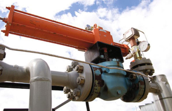
Source: iStock
When triggered, these valves isolate the process plant from the sources of high pressure before the safety parameters of the plant are exceeded, thus preventing loss of containment through a potential rupture. The valves are designed to respond rapidly to a high pressure input signal and will usually complete their activation cycle within 2 seconds of receiving a command signal.
Components of an emergency shutdown system – deluge systems
Water deluge systems are a means of fighting a fire with large amounts of water. They are generally positioned in areas where hydrocarbons are processed or stored, as well as areas where there is the potential for an uncontrolled release of gas which could result in a fire or an explosion.
They work by means of a series of nozzles connected to a piping network. The nozzles are kept permanently in the OPEN position. When an emergency situation arises, the deluge system is activated by the emergency shutdown system, or by one of the other means of activation listed below. This switches on the dedicated fire water pumps, resulting in water being emitted from the nozzles and deluging the area. Figure 2 shows a fire deluge system in action at a road tanker loading area.
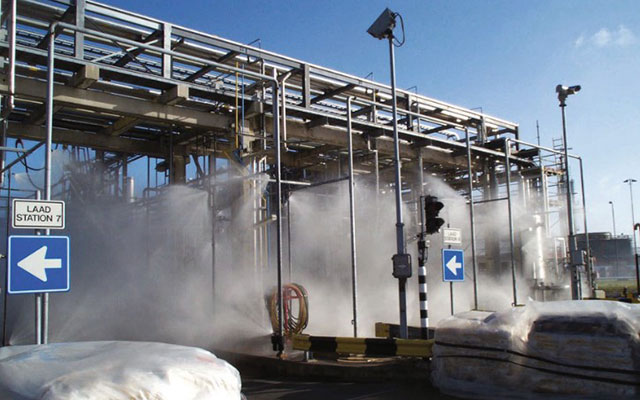
Source: Frontline Fire International
A deluge system can be activated by the following means:
- Emergency Shutdown (ESD) system;
- Electrical (fire detectors);
- Pneumatic (glass bulb detectors);
- Hydraulic (glass bulb detectors);
- Manually;
Components of an emergency shutdown system – fire and gas detection systems
The fire and gas detection system is the sensitive part of the emergency shutdown system. It senses if and where any potential adverse activity has occurred and relays this information to the control room
It is made up of a number of detectors, each of which is specifically selected and strategically positioned so as to raise awareness of an adverse activity at the earliest opportunity so that appropriate action can be taken.
The fire and gas detection system is made up of several types of detectors linked to the emergency shutdown systems.
These detectors might include:
- Gas detection (toxic and flammable);
- Vapour detection;
- Smoke detection;
- Heat detection;
- Flame detection.
The type of detector used must be fit for purpose and suitable for the type of gas or fire likely in the area it is covering. It also needs to cover the area or location where any gas leak or outbreak of fire is likely to occur.
As we’ve mentioned, detectors are generally connected to the remote control room. However, there are occasions when alarms may activate emergency evacuation alarms as well, or simply activate a warning siren or lights.
Components of an emergency shutdown system – vent and blow down system
An essential part of any process system is the vent and blow down system. This is a system that is used to relieve pressure within a process and deal with it in a safe and controlled manner. The pressure relief may involve liquid or gas, depending on the process and/or the situation.
Blow down is normally instigated manually, for example when a system is being prepared for maintenance work and pressure has to be relieved to allow work to commence.
Under normal conditions, hydrocarbons which have been taken out of the process to relieve pressure go to a closed drain header and via the Gas Zone drum (GZ) in order to separate the hydrocarbon liquids from the gases and route the gases to the flare system.

Source: Wise Global Training
However, blow down also has to deal with emergency situations, such as when pressure needs to be relieved because a system has exceeded its maximum safe working pressure. In these cases, the process system will relieve pressure automatically via pressure relief valves and then the blow down system will deal with the exodus of liquid and/or gas.
The type of emergency blow down facility will depend upon the product being processed and the process itself. If the process is of the type that any pressure relief will only involve gas, this might be sent directly to a flare. However, if liquids are involved the system may have to be designed to send these to a dedicated storage tank to be dealt with at a later point.
Level of shutdown
As we mentioned earlier, the level of shutdown needed in response to inputs from an adverse situation needs to reflect the severity of the situation. However, the requirements of each plant, installation or platform will vary accordingly and the shutdown level hierarchy will
reflect this.
To demonstrate this we have set out two shutdown level hierarchy charts, one for an offshore platform and the other for an onshore process plant (Tables 1 and 2)
Safety Integrity Levels (SIL) for instrumentation
Safety Instrumented Systems (SIS)
One of the most critical parts of any emergency shutdown system is the Safety Instrumented System (SIS). A safety instrumented system can be defined as “a system made up of sensors, logic solvers and actuators which has the ability to take a process to a state of safety when predetermined parameters are exceeded or safe operating conditions are breached”.
An example of this might be the sensor (e. g. gas or flame sensor), the controller (the computer logic solver) and the actuator (the electrical device which activates the emergency shutdown device). This is also known as a safety loop.
All of these individual components, and the system as a whole, need to have a level of integrity or dependency which is in line with the consequences of failure. The greater the consequence, the higher level of integrity or dependency needed.
For example, where a loss of containment due to high pressure could lead to an explosion, the functioning of the High Integrity Pressure Protection System (HIPPS) is critical in maintaining a safe environment. The safety instrumented system (safety loop) associated with the HIPPS must have a high safety integrity level to ensure it will work when required.
Safety Integrity Level (SIL)
Now we have covered what a basic safety instrumented system involves, we need to understand the levels of dependability or integrity that may be required. This is known as Safety Integrity Levels (SIL).
There are four discrete integrity levels: SIL1 to SIL4.
The higher the safety integrity level, the higher the associated safety level requirement is, and this needs to be coupled with a lowering of the probability that the safety instrumented system will fail.
The probability of failure is defined numerically as follows:
- SIL 1 – this level of integrity is where the acceptable probability of failure is between 1 in 10 occasions and 1 in 100 occasions. It is required where the potential for relatively minor incidents is involved with limited consequential outcomes;
- SIL 2 – this level of integrity is where the acceptable probability of failure is between 1 in 100 occasions and 1 in 1 000 occasions. It is required where the potential for more serious, but limited incidents is involved and where the consequences may result in serious injury or death to one or more persons;
- SIL 3 – this level of integrity is where the acceptable probability of failure is between 1 in 1 000 occasions and 1 in 10 000 occasions. It is required where the potential for serious incidents is involved and where the consequences may involve a number of fatalities and/or serious injuries;
- SIL 4 – this level of integrity is where the acceptable probability of failure is between 1 in 10 000 occasions and 1 in 100 000 occasions. It is required where the potential for a catastrophic incident exists.
The required safety integrity level for each safety instrumented system is established by conducting a hazard and risk assessment (hazard and operability study or hazard identification study). This will determine the consequences of the safety instrumented system not functioning as required, which in turn will indicate the appropriate Safety Integrity Level (SIL) for that safety instrumented system.
Once the safety integrity level has been established, it is necessary for those who are designing the safety instrumented system to demonstrate that the required level of integrity has been achieved. The design process itself may well go through a hazard and operability study or Common Hazards and Risk Assessment in Oil and Gas Industryhazard identification study assessment in order to analyse the different potential scenarios of failure of the safety instrumented system. This will allow contingencies to be built into the system such as duplication of critical devices such as microprocessors.
Procedures for bypassing Emergency Shutdown (ESD) systems
Bypassing ESD
All emergency shutdown systems and fire and gas systems need to be tested, inspected and/or maintained on a regular basis to ensure they are functioning as required.
These testing and/or maintenance procedures involve the temporary bypassing of safety system interlocks. These are the devices within the logic system which activate the alarm as well as sending a signal to the actuator on the emergency shutdown component itself.
The procedure of bypassing a safety system interlock is known as applying an “inhibit” or an “override”. However, by inhibiting or overriding a safety system in order to test it, this in effect compromises the integrity of any emergency shutdown system during the period the inhibit or override is in place. Consequently, everything possible must be done to ensure the duration of time the safety system interlock is out of action is kept as short as possible.
Furthermore, inhibits should only be applied as part of an established procedure, which should include conducting a risk assessment prior to applying the inhibits in order to evaluate the potential risks during the period the emergency shutdown system is not protected by the safety system interlock.
Inhibits, generally speaking, should only be applied to one protective function at a time and not to groups of protective functions. The total number of inhibits in place at any one time should not be excessive and should always be manageable. Inhibits should be removed as part of the process of finishing the relevant testing or maintenance activity.
The control room operator should also be aware at all times of the application and location of all inhibits. Furthermore, where inhibits are applied through a visual display unit (VDU), there should be a protective system in place which requires a password or key to be entered before an inhibit can be applied. This will prevent any accidental or unauthorized application.
Finally, where an installation is controlled from two different locations, such as a Normally Unmanned Installation (NUI)/remote station onshore, the inhibits which are in place should be visible at both locations. However, where the control of the inhibits moves from one control location to the other, a proper handover protocol should be applied.
Inhibits should only be applicable to protective functions which are graded to:
- Safety Integrity Levels 1 (SIL1);
- Safety Integrity Levels 2 (SIL2).
Protective functions which are graded:
- Safety Integrity Levels 3 (SIL3);
- Safety Integrity Levels 4 (SIL4).
should not normally be capable of being inhibited, as the loss of their safety function is generally regarded as unacceptable.
Bypassing ESD – logging actions and displaying warnings
Whenever an emergency shutdown system or fire and gas system is bypassed, the time the inhibit or override was initiated must be recorded. This is usually covered on a Protective Systems Isolation Certificate (PSIC) or a permit-to-work system, and the inhibit or override is logged and recorded in the central control room.
The particular keys used to inhibit or override a system should also be identified and recorded on the inhibit log until the work is completed and the Protective Systems Isolation Certificate (PSIC) or a permit-to-work system is cancelled and the inhibits or overrides are removed.
When inputs or outputs of an emergency shutdown system are inhibited, they should be allocated a low priority alarm and be visible on the display screen of the control room operator. There should also be a visible indication on the appropriate emergency shutdown or fire and gas panel to show that the system has been inhibited or overridden.
The restoration of the safety system interlock to its normal operating condition will clear the alarm.
All inhibits or overrides should be logged and a record kept.
An inhibit log should record the following information:
- The safety function being inhibited;
- The time and date the inhibit was applied;
- A cross reference to the relevant permit-to-work or protective systems isolation certificate where applicable;
- The time and date of each reassessment;
- The time and date the inhibit was removed.
Other control measures to be applied to inhibits and overrides include:
- They should only be applied with the authority of a senior person or manager;
- They should be time bound at the outset;
- Equipment must be shut down if the emergency shutdown system is not reinstated within the designated time;
- Their implementation should be communicated to all operation personnel as well as adjacent plants.
Blow down facilities, flare types
The term “blow down” refers to the action of venting gas or relieving pressure from a process or production system.
For example, if a system reaches its maximum working pressure and an automatic pressure relief valve vents gas from the system, then the blow down facility will take the gas away to a safe exit point where it will be allowed to escape into the atmosphere, or to a flare where it will be burnt off. This also happens if gas is released during an emergency shutdown event.
Blow down can also be instigated manually, for example when a system is being prepared for maintenance work and pressure has to be relieved to allow work to commence.
When controlling overpressure, it is not uncommon to have both a high pressure and a low pressure vent system. With regards to high pressure vessels, any blow down or depressurization can be a highly hazardous operation. This is because any rapid reduction in pressure can lead to a reduction in a vessel’s wall temperature with the possibility of reaching a temperature below its ductile-transmission level and thus the potential of a brittle fracture occurring in the vessel wall.
Source: iStock
Another consideration of a rapid reduction in pressure is the formation of hydrates if free water is present in the vessel or associated pipework.
Other considerations in the operation of blow down or venting systems include:
- The reduction in temperature of the system and pipework as it relieves the pressure/gas;
- The noise levels during venting;
- The maximum blow down rates and times;
- The liquid which is knocked out of the gas as it vents;
- The appropriate blow down and venting system to be used which meets the type of pressure on the system being relieved (high pressure and low pressure systems being split and independent);
- The system relieving capacity.
Most vent stacks consist of a single pipe which rises above the installation to an elevation which is regarded as safe for the gases to be vented to atmosphere. The system may also have within it a “knock out” facility which will remove any liquids which are suspended in the gas, before it is vented away.
Finally, in the case of a lightning strike hitting the vent system and potentially igniting the gas within it, there is usually a form of snuffing system built into it. This may use CO2 or steam as a means of extinguishing any flames that are caused by the lightning strike.
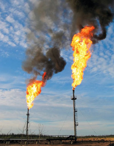
Flare stacks are used to burn off flammable gas when this is released during planned and unplanned events on a process or production system.
They are also used in refineries to burn off purged and waste products, as well as on drilling rigs to burn off unrecoverable gases which can accompany oil extracted from the wells.
Types of flares
Flares work on the basis of introducing air at the point where fuel gas is combusted so that efficient and complete combustion is achieved and smoke is kept to a minimum. Exactly how this is achieved will depend on the characteristics of the fuel gas, including its composition and velocity.
Let’s look at some of the different types of flares used.
Steam assisted flares
These types of flares are the most prevalent in the oil and gas industry. They employ a system which injects steam into the flare at the flare tip. This introduces air into the flame, which makes the flame more efficient whilst at the same time reducing the tendency for the flame to emit smoke. This is an important consideration where installations are close to populated areas. However, injecting steam does increase the noise level emitted by the flare, which can be a problem.
Air assisted flares
Where waste gas pressure is low and steam is not available, then air assisted flares can be used. This type of flare uses a fan to direct air flow to the flare tip. This air flow assists in two ways. First it adds momentum to emission of the fuel gas, and second it provides a contribution towards the air needed for efficient combustion.
Unassisted flares
Unassisted flares use only the pressure of the emission of the fuel gas to provide momentum for the flame. The pressure of the fuel gas helps mix the gas with air for combustion.
Multi-point pressure assisted flares
Multi-point pressure assisted flares use the principle of high exit velocity (at or near sonic velocity) of the fuel gas from each burner. This induces the mixing of fuel gas with air for efficient combustion. Generally each burner is approximately 2,5 metres tall and they are arranged in rows, the formation of which are known as a Multi-Point Ground Flares (MPGFs); the area they cover can be as big as a football field. Some of these multi-point flare systems are capable of handling over 4 400 metric tonnes of gas per hour.

Source: Wise Global Training
In order to cope with the variation of gas volume and still maintain the high exit velocity required, each row of burners is fed by a staging valve. When more fuel gas flows, more valves are opened, and when less fuel gas flows, some of the valves are closed. This ensures that sufficient back pressure is maintained to facilitate the high exit velocity.
Closed and open drain headers, sewers, interceptors
Drainage
With any process or production facility there will always be a residual amount of liquid that finds its way to ground, or there will be a requirement for vessels to be occasionally drained of liquids of some sort so they can be maintained. These requirements have to be accommodated in some way, and the normal method is to provide a drainage system in which the fluids can be collected and dealt with appropriately.
Drainage systems are a means of safely collecting:
- any residual process fluids,
- hydrocarbon liquid and/ or chemical spills,
- deluge water and rainwater.
and transporting it to an appropriate location where it can be dealt with or disposed of appropriately. There are two types of drainage systems: open drains and closed drains. We shall now look at both types in more detail.
Drainage – open drain systems
A drainage system that collects fluids that spill onto the ground is called an “atmospheric drain”, “gravity drain” or “open drain”. This system will consist of collecting funnels or trays known as “tundishes” which are strategically positioned so as to channel any liquid they collect through a series of drain pipes to an open drain header before being routed to a slop tank ready to be dealt with appropriately. Water seals should be fitted on drainage pipes where they transport liquids from one location to another so that they do not act as a conduit for any gas to also travel through the system.
There will be separate drainage systems to deal with “safe areas” and “hazardous areas”.
Drainage – closed drain systems
A drainage system that is required to be connected to a pressure vessel in order to drain off fluids is called a “pressure drain system” or “closed drain system”.
Whenever a vessel is drained of liquid under pressure into a pressure or closed drain system, it must be assumed that the liquid contains a certain amount of dissolved gases. Furthermore, the flow of liquid from the pressurized vessel will be followed by a certain amount of gas (known as gas blow by). This gas, in both its forms, can represent a hazard if it is not dealt with appropriately, e. g. using a blow down facility so that gas is vented away to a flare.
Also, because of the risk this gas represents, a closed drain should never be connected to an open drain system.
Drainage – interceptors
The draining of contaminated water to sewers and/or groundwater must be avoided. Interceptors are a means of collecting contaminated water before it is discharged to a foul drain or surface drain.
Typically, interceptors have three separate chambers with the divisions between chambers extending down to the bottom, and low level pipes connecting the chambers. This is so that when the contaminated water enters the first chamber it can separate (oil will naturally float on top of water) and be extracted. The water is then directed to the second and third chambers via the low level pipe, where any residual oil is also allowed to separate and be extracted. Finally, the water from chamber three is channelled into either a foul or surface drain, whichever is appropriate.
Interceptor systems need to be emptied of residual oil and other contaminates on a regular basis. They are normally fitted with robust visual and audible alarm systems to indicate when these operations need to be conducted. They can also be fitted with automatic closure devices fitted to the retention separators to prevent flow passing through the separators when the quantity of oil in the separator exceeds the oil storage volume. However, there should be a high level alarm system in place to warn the operator when the automatic closure device has been activated so that immediate action can be taken.
REVISION QUESTIONS FOR ELEMENT 3 CONTINUED
Answer 1
Because the petrochemical industry processes large quantities of hazardous material within a contained
environment, it needs to have in place systems which will either prevent loss of containment from happening or mitigate the consequences of such an event if it does happen. These systems are known as Emergency Shutdown (ESD) systems and take the form of various components, each of which is designed to deal with a particular scenario and bring it under control in a safe and effective manner.
Answer 2
- Shutdown of part systems and equipment;
- Isolate hydrocarbon inventories;
- Isolate electrical equipment;
- Stop hydrocarbon flow;
- Depressurize/blow down;
- Activate fire-fighting controls (water deluge, inert gas, foam system, water mist);
- Activate emergency ventilation control;
- Close watertight doors and fire doors.
Answer 3
All emergency shutdown systems and fire and gas systems need to be tested, inspected and/or maintained on a regular basis to ensure they are functioning as required. These testing and/or maintenance procedures involve the temporary bypassing of safety system interlocks which would otherwise activate the emergency shutdown system when testing, inspection or maintenance activities were undertaken.
Answer 4
Interceptors are a means of collecting contaminated water before it is discharged to a foul drain or surface drain. Typically, interceptors have three separate chambers, with the divisions between chambers extending down to the bottom, and low level pipes connecting the chambers. This is so that when the contaminated water enters the first chamber it can separate (oil will naturally float on top of water) and be extracted. The water is then directed to the second and third chambers via the low level pipe where any residual oil is also allowed to separate and be extracted. Finally, the water from chamber three is channelled into either a foul or surface drain, whichever is appropriate.