Ship bunkering is the process of refueling ships with fuel or other supplies. It can be done using different methods such as shore-to-ship or ship-to-ship transfer. Proper safety measures and regulations need to be followed during bunkering to ensure a safe and efficient operation.
Bunkering LNG involves refueling ships with liquefied natural gas (LNG) as a cleaner fuel alternative. This process typically follows strict safety protocols and can be done using specialized equipment and procedures to ensure the safe transfer of LNG to the ship’s fuel tanks.
Description of typical ship bunkering arrangements
Four LNG Bunkering process – standards and rulesmethods of bunker supply are detailed in the following sections.
The duration of the bunkering will depend mainly on the transfer rate from the bunkering facility; different pump sizes or pressurised supply can be selected depending on the specific needs. Other parameters influencing the duration include the testing procedures, BOG and flash gas handling, purging and draining method and pre- and post-bunkering procedures.
Ship-to-ship LNG bunkering
LNG bunker ships are a common solution when there is a significant volume of LNG to be transferred. Current capacities of LNG bunker ships, in operation and under construction, are in the range of a few hundred to several thousand cubic meters.
The bunker ship is loaded either in a purpose-built, small-scale terminal, a standard LNG terminal adapted for small scale LNG carriers or ship-to-ship bunkering from a larger LNG carrier.
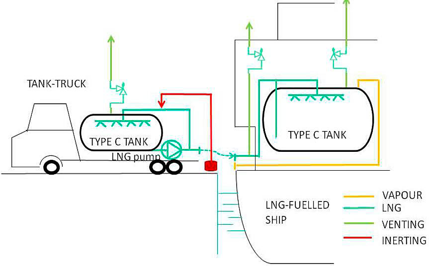
Truck-to-ship LNG bunkering
LNG bunkering operations are carried out from standardised LNG trucks (typically about 40 cubic meter capacity). More than one truck may be required to bunker a single ship, depending on the required bunker volume.
The LNG bunkering operation duration is dependent on the transfer capacity of the truck which is relatively small. Depending on the shore side arrangement it may be possible to increase the bunker rate to some extent by simultaneous bunkering from multiple trucks via a common manifold or using a permanently installed buffer station on the quay side.
This LNG bunkering method is recognised to be flexible as it offers the possibility for many different ships to be bunkered in different port locations. Depending on the port arrangement it may be possible to park the trucks close to the bunker station on the receiving ship allowing short hoses to be used, this potentially reduces the heat flux into the LNG, minimises the pressure drop and also reduces the size of a potential spill if the hose is damaged.
This method is recognised as most suitable where the amount of LNG to be transferred is less than 200 cubic meters and when the commercial operation of the ship allows a sufficient duration for bunkering.
In some cases, LNG trucks may bunker Ro-Ro ferries directly from the ship’s main open cargo deck to the bunker station. This bunkering method derives from normal practices of oil fuel bunkering methods used in Ro-Ro ferries.
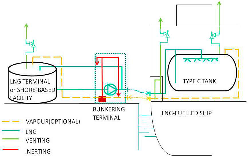
Terminal (or shore-based facility) to ship LNG bunkering. A permanent bunkering facility may be used by ships such as short sea shipping ferries, ro-ro ships, OSV and IWW vessels. LNG bunkering takes place through a rigid cryogenic pipe and a flexible hose or loading arm for final connection with the ship. The tanks for the storage of the LNG should generally be as close as possible to Ship to Ship Bunkering Operations of the Liquefied Natural Gasthe bunkering terminal.
It is expected that this type of facility will be manned such that there will be shore side personnel able to manually activate the ESD and stop the bunker transfer in case of an emergency.
Containerised LNG tanks used as fuel tanks
This bunkering method may also be referred to as using portable tanks (see IGF code 18.4.6.3 and 18.4.6.4).
Instead of transferring LNG into the receiving ship’s tanks pre-loaded LNG containers are lifted on board the vessel as a complete fuelling package. Each container is connected to three different piping systems: the LNG fuelling line to the engines, piping to the vent mast for the pressure relief valves (PRV) of each container and the inert gas system.
In case of use of ISO containerised LNG tanks used on board some small container carriers (feeders), the LNG tanks are provided in standard container sizes and consist of a Type C LNG tank, similar to a road tanker, inside a container shaped steel frame. The connection system for the LNG tank is also located within the frame.
Read also: Basic Information about Liquefied Natural Gas Bunkering Operations
For trailer tanks, used on-board some ferries, they are parked in specific location, usually IMDG areas, where they are fixed to the deck and connected through adequate hoses for the LNG fuelling in navigation. The specific LNG trailers (and its connecting equipment) used as portable LNG fuel tanks on board should be approved according to IGF code in addition to approval according to national, regional or international standards, e. g. ADR, Transport Canada or US DOT.
Examples of ship bunkering arrangements
Possible ship bunkering options are given in table below with corresponding arrangements (Figures 3 to 7).
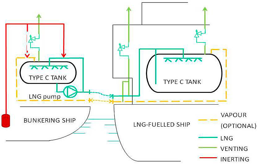
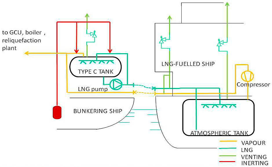
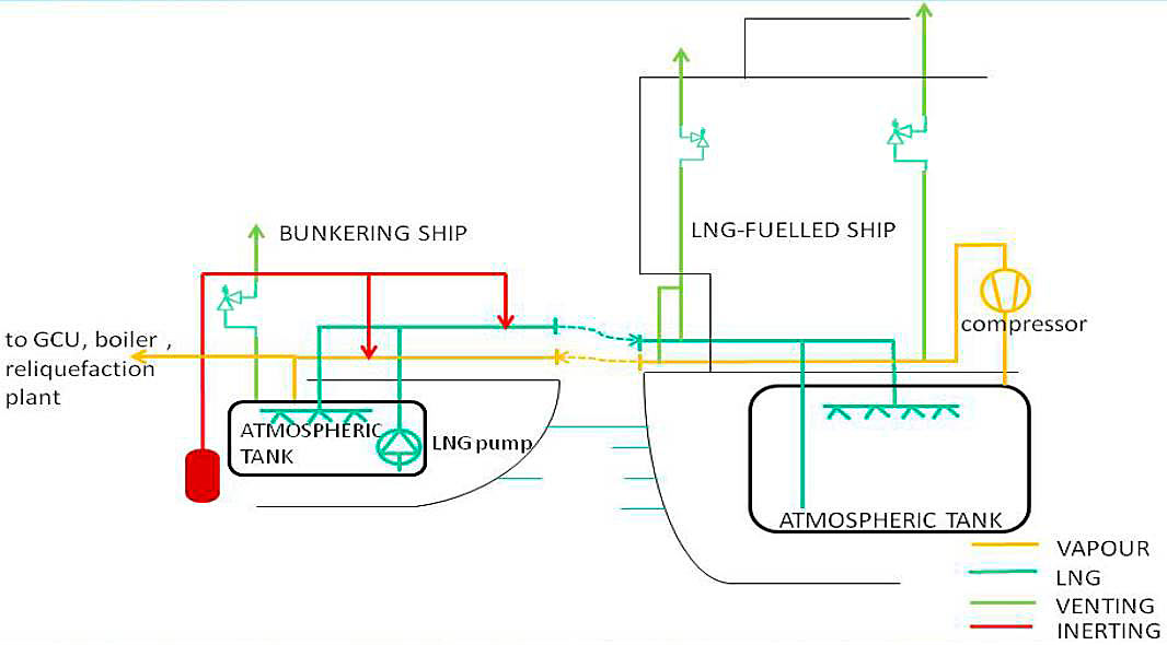
Compressor is optional, only necessary if free flow is not possible. Normally there is no need for a compressor if the bunker ship uses atmospheric tanks or uses type C tanks operated at very low pressure (using discharge pump and not PBU). It is only required in cases where there is likely to be large quantities of flash gas generated during bunkering and the pressure gradient between the bunker ship and receiving ship does not allow free flow of vapour.
| Bunkering options and arrangements | ||||||
|---|---|---|---|---|---|---|
| Bunkering facility | ||||||
| Type C tank | Atmospheric tank | |||||
| Bunker ship | Tank truck | Shore-based facility | Bunker ship | Shore-based facility | ||
| Receiving ship | Type C tank | Fig. 3 | Fig. 6 | (*) | (*) | Fig. 7 |
| Atmospheric tank | Fig. 4 | (*) | (*) | Fig. 5 | (*) | |
| (*) This arrangement is possible but not shown. | ||||||
Note: For small scale bunker supply using Type C tanks, the LNG supply pressure may be generated by pump (as shown in the figures below) or by a Pressure Built Up unit.