Gas production projects are today under development or scheduled in a short future. Offshore LNG gas production raises different problems associated with the sloshing of the liquefied gas in the tanks, both for gas carriers and for LNG–FPSO‘s. This is why effect of sloshing in tanks should be noted.
Summary
New requirements for gas carriers will consider any conditions of filling rates in the tanks, in order to account for emergency departures. Partial filling rates are also mandatory when investigating possibilities to store gas on floating production platforms. Sloshing of liquefied gas in tanks of gas carrier has always been studied in two steps: investigating first the ship motions in waves and secondly applying the calculated or measured motions to the tank in order to obtain the liquid motions. This method is not fully correct representation of reality, as coupling is not taken into account and could play a large role in the ship motion hence the liquid motion itself.
A joint effort was launched in 2003 by several companies to study the effect of coupling on the seakeeping. Model tests were conducted in November 2003 with a free sailing gas carrier and a moored FPSO, equipped with two tanks filled with water at various filling rates.
The article will review both the model tests and numerical results obtained for the two vessels with partially filled tanks, taking into account the full coupling between the vessel and its liquid cargo.
Nomenclature
- An – sloshing amplitude.
- B – damping matrix.
- g – acceleration of gravity.
- Ma – added mass matrix.
- – hull normal vector.
- Ni – component of the normal vector.
- RAO – Responce Amplitude Operator.
- φ – hydrodynamic potential.
- ω – pulsation.
- η – tank wave elevation.
Introduction
Coupling affect design with the following features:
- For the tank: sloshing excitation.
- For the floater: maximum motion.
- For the offloading system: operation feasibility.
This implies that a design tool shall predict coupling effect with a “good enough” accuracy in order to gain in terms of design reliability.
A dedicated Joint Industry Project called SALT (“Seakeeping of structures Affected by Liquid Transient”) about the coupling effects has been set up by PRINCIPIA in the course of 2003. Three main tasks have been included in the scope of work:
- Model test on industrial configurations for seagoing gas carrier and moored FPSO;
- Comparison between model test and DIODORE numerical results;
- Deriving a methodology to use coupling model and to identify sloshing critical cases.
The present article summarises the two first steps and then introduces the problematic of the last step.
Model Tests
Introduction
Coupling effects between floater and tank content is a well-known phenomenon already studied extensively through model tests for anti-roll tank application. In such cases, the volume of liquid in tanks is close to 1,5 to 3 % of the ship displacement. In the case of partially filled tanks of gas carrier, the volume of liquid in the tank can go up to 70 % of ship displacement. The standard approach to test the seakeeping performance of LNG carrier is to model ballast or fully loaded condition without any liquid in the tanks. The present set of model tests was performed with free sailing self-steered model of a large LNG carrier and a FPSO at anchor.
Model, Measurements and Test Set-Up
Two existing models were used during this joint industry project: one LNG carrier and one box type FPSO. In order to cope with the large difference between water and liquefied gas density, Cargo Containment Systems of LPG and LNGtwo prismatic tanks (out of four or five for real configuration) were modelled and filled with fresh water. The idea was not to reproduce perfectly reality (as it is anyway nearly impossible to find the correct fluid characteristics at model scale), but to provide model tests results with full coupling to be used for numerical validation. On the other hand, taking half of the real tank volume with a liquid of about twice density would ensure that the global reaction forces of the sloshing liquid and the resulting coupled floater motions would be rather realistic. The aft and forward tanks were located such that the global reaction forces of the liquid on the floater would be roughly good for all 6 degrees of freedom.
The forward tank was mounted on a 6-component frame attached to the model, in order to obtain directly the liquid reaction forces. The inertia forces due to the accelerations of the 6-component frame, tank and steel frame were of course subtracted to the measured force.
This was obtained by waiting the empty set-up and measuring accelerations at the centre of gravity of the instrumented tank. The method was checked during tests with empty tanks, where no reaction forces were measured.
The same two tanks and 6-component frame set-up were used in both models.
The model of the box type FPSO was mounted in a soft spring arrangement. Only zero speed tests were performed, for a variety of sea state, wave direction and filling ratio.
The model of the gas carrier was self propelled and self steered. The vessel was tested at zero speed and in transit for a variety of sea states, wave directions and filling ratio.
For both models, the tested filling ratio were 18 %, 37 % and 56 % of the total tank height. The GM and draft were kept constants in all conditions, except for the highest filling ratio for the LNG carrier were the GM was decreased due the difficulty to tune correctly the mass distribution with such large amount of water in the tanks.
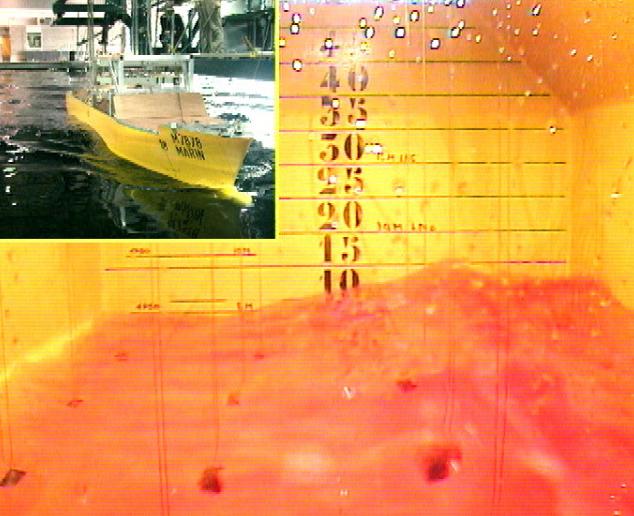
On top of the standard Basic Ship Motions and Mathematical Model used in Vessel Simulator (VeSim) Toolmeasurements of ship motions, accelerations, mooring forces (for the FPSO), elevation of water inside the tanks and tank reaction forces, the activity of the liquid in each tank was also observed thanks to onboard cameras. The severity of the sloshing and the observation of impacts on the tank walls and ceiling were noted, in order to identify the most critical cases to be studied numerically. No pressure measurements were done in the present JIP, that focused on coupling effect between the floater and its liquid cargo.
Results of Model Tests
A General Observations
Strong coupling was observed in many conditions as expected. Pure head and beam seas provided 2D sloshing modes in longitudinal and transverse direction respectively. In bow-quartering seas, the modes in the tanks were more confused, with of course transverse and longitudinal wave systems, but also diagonal and curling modes for the most confused cases. In terms of coupling, beam seas was the most interesting case. The lightly damped roll motion was of course the most vulnerable one in terms of coupling.
For transit conditions, stern-quartering seas did not yield heavy sloshing in the tanks but rather large coupling was measured. In head and bow-quartering seas, speed variations due to liquid motion were measured, originating from longitudinal sloshing.
B Effect of Coupling on First Order Motions
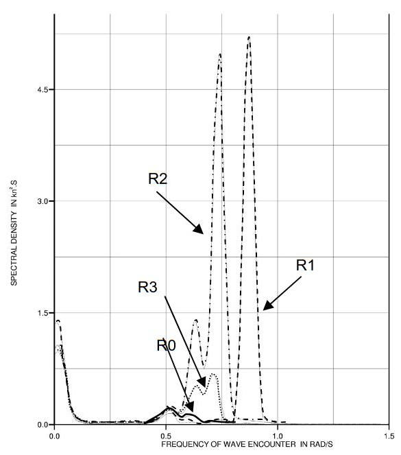
Standard deviation of motions were compared in the same wave condition for different filling ratio (R0 denoted the case without water and R1 to R3 the cases with increasing filling ratio). Picture 2 presents the results of one test in beam seas.
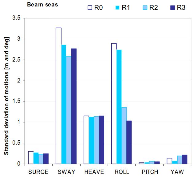
The results show no large coupling in surge, heave and pitch, but more in sway and yaw and even larger in roll. The largest filling ratio yields a factor 3 decrease in roll motion. Corresponding sloshing in the tank is of course also large in that case.
The coupling is also clearly observed on the roll response. The following figure shows the response of roll in beam seas for the moored FPSO.

The same type of results were found for the FPSO and the LNG carrier at anchor.
C Effect of coupling on second order motions
Surprisingly, second order motions also proved to be affected by the coupling. This is shown in Pic. 4 for the drift forces (transverse drift in beam seas) and in Pic. 5 for the mean moment on the mooring lines of the soft spring arrangement.
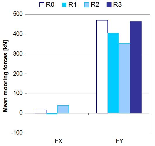
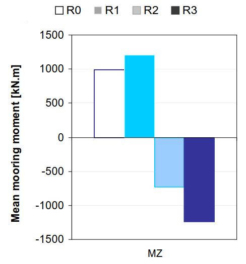
This effect should be bared in mind when testing moored platform with large volume of liquid sloshing in tanks. The actual set-up was not a correct model of a mooring arrangement, the soft-spring set-up being just present to keep the model at fix heading.
The same applied to the gas carrier in transit with speed variations due to longitudinal sloshing, especially from the forward tank. This sloshing was interfering with both first order and second order speed variations.
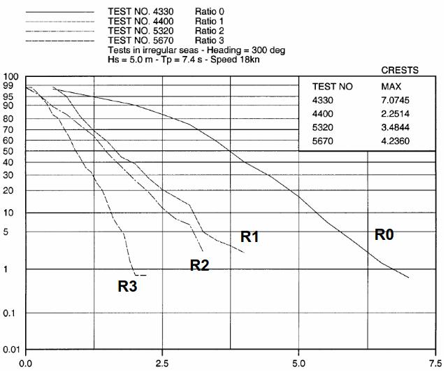
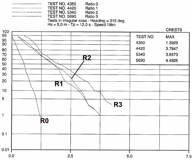
D Effect of Coupling on Roll in Stern-Quartering Seas
Finally, coupling was also studied in stern-quartering seas for the gas carrier in transit. For this heading, where non unique relation between the encounter frequency and wave frequency exists, no response function can be obtained. The effect of coupling was then looked at through the distribution of roll amplitudes, as shown by the following figures. In one case the two tanks acted as anti-roll tanks, reducing the amplitudes of roll motions (see Pic. 7), in another case with slightly different heading, the two tanks actually increased the roll amplitudes (see Pic. 8).
Numerical Model
This part is devoted to the presentation of the theoretical model and its implementation within the hydrodynamic software DIODORE developed by PRINCIPIA.
Sloshing in Tanks
The first step is to determine the natural sloshing modes for each tank at its filling rate. This means obtaining the non-trivial solutions of the following boundary value problem:
- Δφ = 0 within the fluid volume; Eq. 1.
- = 0 on the tank wall Sc; Eq. 2.
- gφz-ω2φ = 0 at the free surface; Eq. 3.
Then as it can be demonstrated that the potentials form an orthogonal and complete basis at the free surface, the wave elevation in any tank can be derived from:
with:
Now we consider the tank undergoing forced motion:
- Δφ = 0 within the fluid volume; Eq. 5.
- = Ni on the tank wall Sc; Eq. 2.
- gφz-ω2φ = 0 at the free surface Sf; Eq. 3.
with Ni stands for one component of the generalised normal vector.
After resolution of the problem, one can relate the sloshing amplitude of the n mode to the forced motion amplitude Xi through the following expression:
with:
On the other hand, introducing the general force tensor F:
Coupling with Ship Motion
The coupling between the tanks sloshing modes and the ship motions amplitude is then solved through the following equations:
Roll damping is linearised stochastically and has been identified using preliminary model test results.
Numerical Results/Model Tests Comparison
As detailed earlier, the following configurations have been tested and compared to DIODORE results:
- Spread moored LNG FPSO (zero speed).
- Spread moored LNG Tanker (zero speed).
- LNG Tanker in transit.
The spread mooring was simplified with a simple soft- spring arrangement, which aim was only to keep the heading constant during the tests.
Theses comparisons have permitted to validate the numerical model both with and without forward speed. It also permits to define the validity limits in terms of filling ratio, sea states.
Coupling Effects
The major coupling effect is as expected and confirmed from the model tests observed on the roll motion. Pictures 9 to 12 shows the roll response in beam seas for the moored FPSO for all four filling configuration.
The agreement between the calculations and the model tests are good.
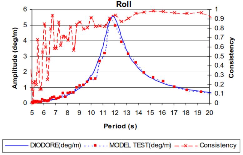
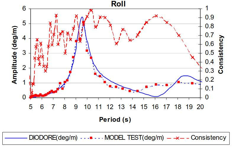
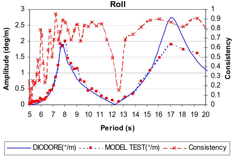
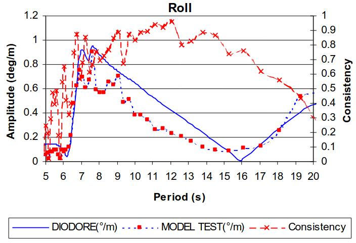
The coupling pattern is the following:
- A first peak around the transverse natural period.
- A second peak at the ship roll natural period.
- An extinction is observed between these two peaks. It must be noted that this extinction is completely numerical due to the linearity of the model whereas non linear damping in the tanks leads to a non-complete extinction for the model test.
Sloshing and Tank Reaction Force
The wave elevation and loads measured in the tanks have been computed with DIODORE and compared to model test results.
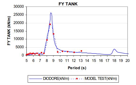
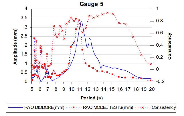
The latter graphics show the general good agreement between DIODORE results and model tests.
Methodology
During a workshop, the JIP partners have exchanged their views about the coupling issue and its effect to their related design or verification methodology.
Currently, the identification of the sloshing critical cases relies on the 2 following assumptions:
- Identifying the floater largest motions or accelerations;
- Identifying the risk of sloshing in the tank.
Indeed results from model test leads to the conclusion that coupling effect between the tank sloshing mode and the roll motion are large and modify significantly the roll RAO but also wave elevations in the tanks.
The following graph presents the ratio between the different filling ratio and the solid case for roll motion (significant value):
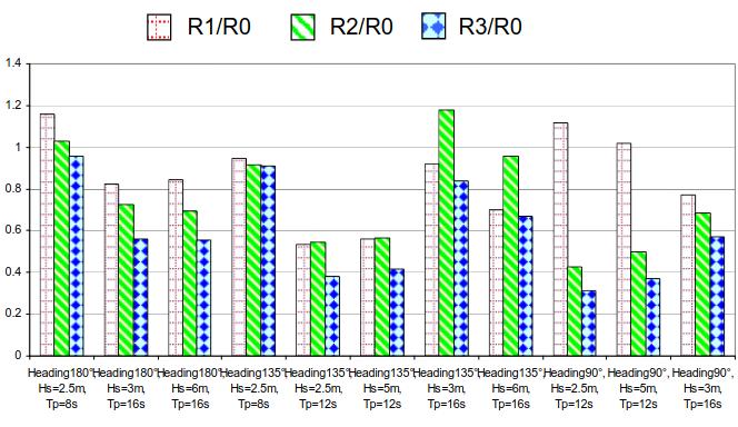
One can see that coupling effects are significant and can leads to both lower roll motion than with solid model or higher roll motion than with solid model.
Conclusion
Model tests were successfully performed for a free sailing gas carrier and moored FPSO equipped with two prismatic tanks filled with different water levels. As expected, large coupling was observed during the model tests. Both first order and second order motions were affected by the coupling. The model tests covered a large array of headings, wave conditions and filling ratio.
This joint industry project has permitted to complete an extensive validation of a coupling 1st order model in the hydrodynamic software and to exhibit the domain of validity of a 1st order model. It is also a large database in order to assess coupling in design methodology.