The article describes a study on the optimized and practical support arrangement of a cargo tank for Tank Type-A LPG ships, emphasizing possible reduction in number of tank supports based on a force distribution as well as the strength of the cargo tank and its supports. With the increasing newbuilding of LPG ships, the needs of design development for the support arrangement of the cargo tanks are discussed. Especially, the benefit of reducing number of supports is expected to be substantial with respect to reduced construction time and increased productivity. The cargo tank supports are specially considered, taking the effect of interaction between the double bottom structures and cargo tank into account.
- Summary
- Introduction
- Cargo tank, hold space and tank supports
- General
- Support arrangement
- Design parameters and existing support arrangement
- Cargo hold analysis
- Design load cases
- Global finite element model
- Design acceptance criteria
- Reaction force in supports
- Vertical supports
- Transverse supports
- Optimised support arrangements
- Vertical supports
- Transverse support
- Conclusion
Summary
For four different sizes of LPG ships, design parameters and total number of the supports are outlined. The force distribution in the supports is investigated based on cargo hold finite element analyses in accordance with applicable classification rules and procedures. The change in distribution of forces in the supports, after removing some of the supports with low utilization, is shown. In addition, the consequences of reduction in number of supports with respect to scantlings of the cargo tank and the supports are also considered.
The intention of this study is to provide information regarding optimized and practical design application to the support arrangement of cargo tanks in consideration of construction and inspection, and existing support arrangements will be reviewed with respect to that. In order to provide an optimal support arrangement of a cargo tank, comprehensive integrated structural analyses comprising both cargo tank and hull structure is necessary. This analysis has to be based on IGC code, applicable rules and procedures.
Introduction
For transportation of LPG (Liquefied Petroleum Gas) and chemical gases (VCM, NH3 and volatile chemicals) two alternative types are presently employed:
- Pressure vessel type tanks, Independent tanks, type C (MARVS < 0,7 bar)cargo tank type C.
- Independent prismatic tanks, Independent tanks, type A (MARVS < 0,7 bar)cargo tank type A.
Tanks of pressure vessel are structurally simple geometric shapes such as spherical, cylindrical or bilobe. These tanks are supported by two saddles. Independent prismatic tanks are usually constructed of plane surfaces with various keys and support arrangements.
Tanks of pressure vessel type are normally insulated and fitted with a refrigeration plant. Provided design pressure is at least equal to the vapour pressure of the cargo at a temperature of 45 °C, uninsulated cargo tank with no refrigeration plant is possible for the smaller vessels. However, insulation is always required for independent prismatic tanks and a refrigeration plant is fitted to maintain the cargo vapour pressure near atmospheric pressure.
For ship size less than 25 000 m3 type C tanks are dominating, while for larger vessels only type A tanks are applicable.
Depending on economical, technical and operational considerations, pressure vessel type tanks or prismatic type tanks are chosen.
The trend of current LPG newbuilding is that cargo capacity is varying up to 82 000 ~ 85 000 m3 and most of the LPG newbuilding ordered in the recent years are large ships with cargo tanks of type A.
The structural behaviour of tank supports of LPG ships is highly important as the supports are main members to transfer tank loads into hull structures. Hence, the design and construction of the tank supports are to be specially considered.
From construction point of view, when installing a cargo tank proper cleaning in way of tank supports, wood installation, resin pouring work, final insulation and inspection are usually performed based on the established practices and procedures. Such works are however very time consuming and it requires special attention to achieve sufficient quality and accuracy. With the increasing newbuilding of LPG ships, the needs of design development for the support arrangement of cargo tanks have been discussed based on practical experiences.
Possible reduction in number of the tank supports is regarded as one interesting option. The benefit of reducing number of supports is expected to be significant with respect to reduced construction time and increased productivity for the shipyards.
For four different sizes of LPG ships, main characteristics in view of design parameters and tank support arrangements are outlined. The force distribution in the supports is also investigated based on cargo hold finite element analyses done in accordance with IGC code, applicable classification rules and procedures.
The change in distribution of forces in the remaining supports after removing the supports with low utilization is reviewed. The consequences of this change in the cargo tank and the supporting hull structures are also considered, since the magnitude and redistribution of reaction forces has considerable impact on the structural response of the cargo tank and the supporting double bottom structures.
The intention of this study is to provide information regarding optimised and practical design application to the support arrangement of a cargo tank in consideration of construction and inspection.
Cargo tank, hold space and tank supports
General
LPG Tank Type A ship is structurally composed of independent cargo tanks, cargo tank supports and hull structures. The cargo tank is divided at the centreline by a liquid tight bulkhead with opening in way of cargo tank dome forming a common vapour space. To prevent sloshing by excessive free surface movement of the liquid cargo, a transverse swash bulkhead is usually fitted at the mid length of the tank. The cargo tank is placed on vertical supports at inner bottom of hull structure, and structurally asymmetrical due to vertical transverse web frame in way of centreline.
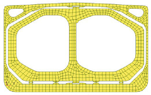
Typical midship section with cargo tank and its supports for Tank Type A LPG ships is shown in Figure 1.

Cargo tank is supported by:
- vertical supports,
- upper and lower transverse supports,
- anti-pitching supports and anti-floating supports.
Hold space between cargo tank and hull structure is filled with dry inert gas when transporting flammable gases. In addition, there are some technical aspects to consider in terms of material selection, tank supports, insulation and access within the void space. Narrow space from ship’s inner bottom to bottom of insulated cargo tank makes it difficult to do maintenance work and inspection of tank bottom supports. As a prime safety characteristic of Tank Type A LPG ships, the hull members surrounding the cargo tank is forming a secondary barrier and is designed to keep the cargo within the void space in the event of leakage from the cargo tank.
The cargo tank supports shall be designed to fulfil the following purposes:
- To transmit the loads of weight of cargo tanks and cargoes due to the ship motions to the hull structure.
- Anti-floating of cargo tanks when hull structures are flooded.
- Anti-pitching against ship collision.
Support arrangement
Normally, the following supports are employed:
- Vertical supports.
- Transverse supports.
- Anti-pitching supports.
- Anti-floating supports.
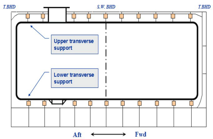
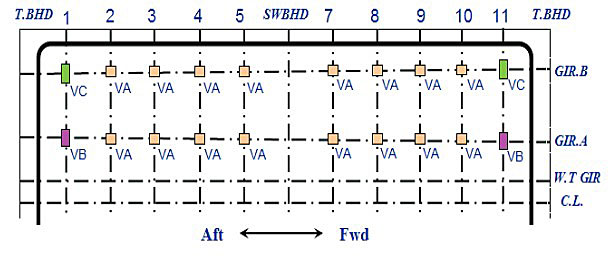
Figure 2 shows an example of a support arrangement of a cargo tank at ship’s inner bottom and centreline. Vertical supports are arranged at junctions between double bottom floors and girders at every web frame position, upper/lower transverse supports at centreline and anti-pitching support at swash bulkhead position, respectively. The supports and keys are symmetrical about centreline, but the tank support arrangement can be different based on design parameters of each ship.
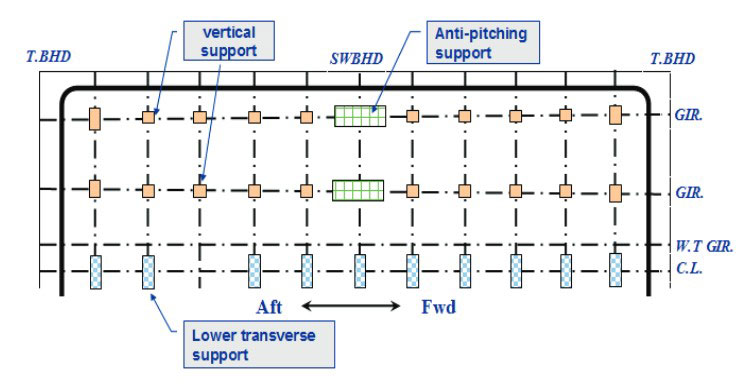
1 Vertical Support
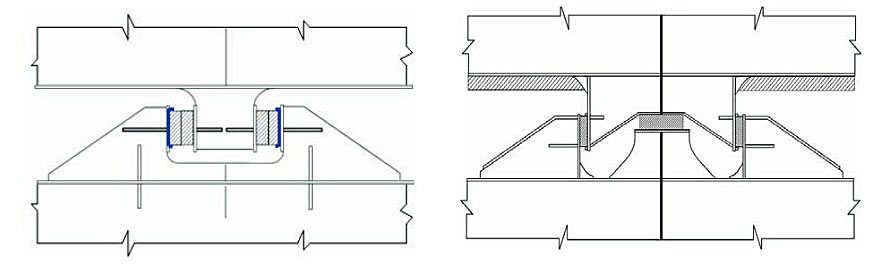
Static and dynamic loads of a cargo tank are transferred to hull structures through vertical supports which should be designed to prevent hull structures from excessive stress concentration. Vertical supports are also subject to horizontal forces due to friction, e. g. due to the local horizontal movement of the cargo tank due to thermal expansion and contraction caused by temperature variation of the cargo tank.
Figure 3 shows example of vertical support. Between the cargo tank support and the support on hull structures wood is normally mounted with thin steel surface layer. Resin is applied to obtain levelling of the vertical supports in a cargo hold. Dam plates are fitted to provide strength margin for horizontal forces and to avoid movement of wood in case of damages in resin.
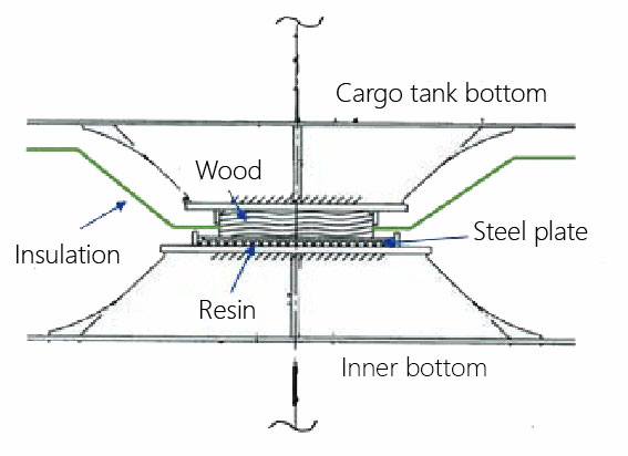
The strength of wood and resin should carefully be checked in view of compressive strength and shear strength.
2 Transverse Support
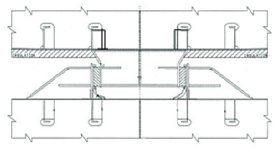
In order to support a cargo tank in the transverse direction, horizontal supports are arranged at centreline (inner bottom and deck level) at every web frame position. The key and supporting hull structure should be designed based on the maximum transverse forces corresponding to a static heel angle of 30° according to IGC code.
As one of design consideration the protruding part, key, should be fitted to the cargo tank side with a gap of 1~2 mm at one side between wood surface and steel surface, to prevent potential problems caused by low temperature of liquefied cargoes.
Figure 4 is showing a key on cargo tank bottom and a lower transverse support at ship’s inner bottom.
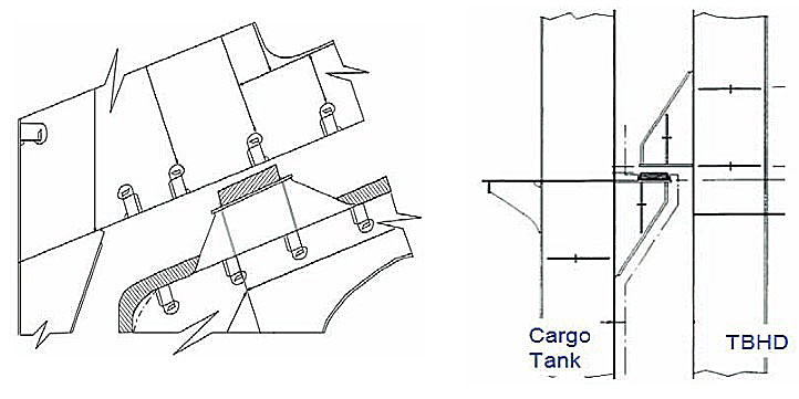
3 Anti-pitching/longitudinal Support
The anti-pitching supports are arranged at one cross section of the cargo tank in order to withstand longitudinal collision forces without permanent deformation of tank structure or supports. The collision forces acting on the cargo tank should correspond to acceleration 0,5 g in the forward direction and 0,25 g in the aft direction.
Independent or combined types of anti-pitching supports are employed as shown in Figure 5, depending on number of girders and floors in the double bottom structure.
4 Anti-floating Support
The anti-floating support arrangement should be suitable to withstand an upward force caused by an empty cargo tank in a hold space flooded to the summer load draught, which could damage the upper deck and top side wing ballast tank, without plastic deformation of hull structure. Anti-floating supports are normally arranged at upper slope area of the cargo tank. In some designs, the supports are arranged at end bulkheads as shown in Figure 6.
Design parameters and existing support arrangement
The design of four different sizes of Tank Type A LPG ships is investigated with the main focus on the total number of keys and supports. Some of the key elements with respect to number of supports are as follows:
- Number and length of cargo tank.
- Transverse web frame spacing.
- Support arrangement.
The principal particulars and design parameters of the four different LPG ships are shown in Table 1, two (ship A & B) with four cargo tanks and two (ship C & D) with three cargo tanks.
The tank length is based on the cargo tank in middle of cargo area and can be different from that of fwd. and aft cargo tanks. Regarding web frame spacing, one design (ship D) is relatively smaller than other designs.
Table 2 shows the total number of keys and supports fitted in cargo tanks and hull structures for each ship and indicates high variation from 460 to 578, depending on the number of cargo tanks, transverse web frame spacing and tank support arrangement.
Three ships (ship A, B and D) have anti-floating supports arranged in way of upper slope of cargo tank while one ship (ship C) has anti-floating supports in way of cargo tank end bulkheads, as shown in Figure 6.
The main characteristics of the four different sizes of ships in terms of keys and supports are summarized as follows:
- The number of vertical supports are in the order of 48~53 % of the total number of supports.
- The number of supports is the highest for ship D due to relatively reduced transverse web frame spacing compared to the other three cases.
- Anti-pitching keys and supports are normally arranged with four set for each cargo tank.
- The number of anti-floating supports for case C is the highest as the supports are arranged at both cargo tank and hull structures.
As clearly illustrated in the Table 2, the design parameters, especially transverse web frame spacing and support arrangement, have significant effect on the total number of supports.
Cargo hold analysis
For Tank Type A LPG ships, a structural analysis shall be carried out for the evaluation of a cargo tank, cargo tank keys/supports and hull structures in accordance with IGC code, applicable rules and procedures.
In advanced structural analysis, cargo tanks, cargo tank keys/supports and hull structures have to be modelled and analysed. The review of the cargo tank supports are specially considered taking the effect of interaction between cargo tank and hull structures into account.
Design load cases
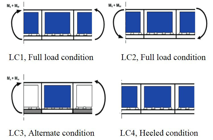
The design load cases are selected based on actual loading conditions from vessel’s loading manual. Therefore, all possible conditions such as seagoing (upright and heeled) and damaged condition are included.
The design load cases should include fully loaded condition and alternate conditions (realistic combinations of full and empty cargo tanks) with static/static + dynamic sea pressure and tank pressure, giving maximum net loads on the double bottom structures. Therefore, the double bottom structures must be considered for maximum net internal loads and for maximum net external loads.
Read also: Structural Aspects of Liquefied Petroleum Gas Cargo Tanks Design and Construction
Design loads, typically design bending moments and maximum cargo accelerations and sea pressure, are applied to a global cargo hold model. The loads are calculated for a 20 year return period in the North Atlantic and serve as basis for design against yield and buckling strength of the cargo tank, supports and the supporting double bottom structures. The basis for the selection is to maximize the cargo tank and hull stress response by combining internal and external loads with hull girder bending.
The design load cases in Table 3 are mainly reviewed in this study as most critical and dominating conditions among standard design load conditions in current procedure in view of reaction force.
Design load cases are shown schematically in Figure 7.
Global finite element model
A global finite element model is established to analyse structural adequacy of primary members of the cargo tank and hull structures under combined loading from external loads, internal loads and hull girder bending. We will also obtain reaction force in the supports.
The global finite element model is based on 3 and 4 node shell elements for the triangular and quadrilateral elements. The beam elements are modelled as 2 node beams.
Full breadth model should be made for the analysis considering asymmetric nature of structural layout of the cargo tank and design load cases.
The extent of the global finite element model is shown in Figure 8 with tank no. 3 plus half of tank no. 2 and 4 (1/2+1+1/2), where the middle tank/hold of the model is normally assessed against the design acceptance criteria.
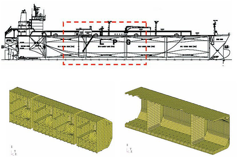
Figure 9 shows a regular mesh with the element size of stiffener spacing for cargo tank and hull structures. The supports are idealized by shell elements.
The supports are interconnected by beam element for material of wood between cargo tank and hull structure in order to get a reasonable reaction forces in supports. It should be noted that as cargo tank supports do not transfer any tensile load some iterative procedure may be required to eliminate connection elements subject to tensile stresses.
All structural elements are modelled based on the net scantlings, and the net scantlings are obtained by deducing corrosion addition as specified in DNV Classification Rules.
Design acceptance criteria
The design acceptance criteria are based on yield and buckling check. Allowable membrane stresses with respect to equivalent von Mises stress and shear stress as shown in Table 4. This is applicable to strength evaluation of primary members of a full cargo tank and the supporting double bottom structures inclusive keying structures.
- σe 0 equivalent von Mises stress, N/mm2.
- τm – mean shear stress over a net cross section, N/mm2.
- f1 – material factor depending on material strength group.
Buckling control shall be carried out with the following usage factors as shown in Table 5 when the local load and global load is at 10-8 probability level.
Reaction force in supports
Ship A (82 000 m3 LPG ship) in Table 1 is considered in this study.
The calculated reaction forces in supports are processed in order to estimate the design loads for the support which is used as basis for evaluating the strength of supports. To account for interaction between the cargo tank and double bottom structure, the effect of hull girder bending on the reaction force distribution at different locations is investigated. In addition, the critical areas for the cargo tank and the double bottom structure corresponding to design load case are also presented.
Vertical supports
1 Reaction Force Distribution
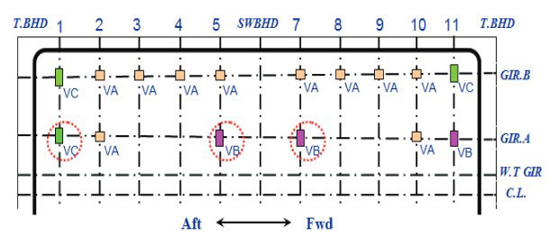
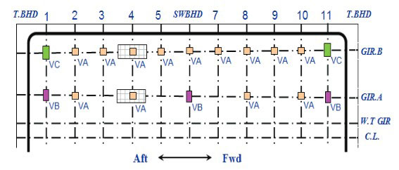
Vertical support arrangement of ship A is shown in Figure 10 where the vertical support is divided into three types based on the design loads. The magnitude of the calculated reaction forces is shown in Table 7.
Hence, the design loads is assumed to be as follows:
- Type VA: 650 ton.
- Type VB: 1 100 ton.
- Type VC: 1 500 ton.
One important design consideration in the detail design of each different type of the vertical support, the strength of wood and resin has to be reviewed and verified against a safety factor of 3.
Transverse web frame position is numbered from aft to forward direction and port side is only presented due to symmetric support arrangement.
The sum of the calculated reaction forces over the vertical supports is checked and compared with the total weight with the applied maximum vertical acceleration and gravity as shown in Table 6.
Table 7 shows the calculated reaction forces in supports for design load case LC1~3 and illustrates high variation in magnitude. It is observed that maximum reaction force is 1444 ton at location 1 of GIR. B for LC3.
A comparison of the calculated reaction force distribution at different locations is illustrated in Figure 11. It is observed that LC3 gives high reaction force at location 1 and 11 close to end bulkheads while LC2 gives it at location 5 and 7 in way of mid supports.
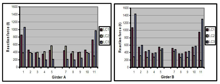
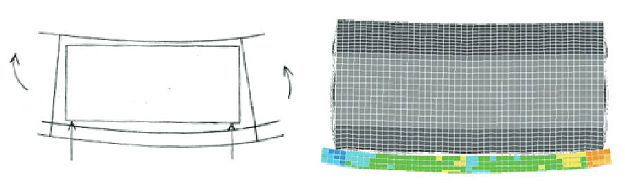
It can be explained for LC1 and LC3 by the fact that high reaction forces in those areas are caused by a combined effect of deformation of the double bottom structure due to maximum internal pressures + hull girder bending (sagging) as shown in Figure 12. On the other hand, maximum external pressure + hull girder bending (hogging) in LC2 is opposite.
In addition, the reaction force at location 1 is found to be higher than that at location 11 in LC1 and LC3 due to the structural arrangement in way of transverse bulkhead. The relatively higher reaction forces are also found at outboard supports (GIR.B) than at inboard supports (GIR.A) in LC1 and LC3.
2 Effect of Hull Girder Bending
To investigate the effect of hull girder bending in view of reaction force at different lo cations, cargo hold analysis without hull girder bending is carried out and the calculated reaction forces are compared with those in the Table 6.
Figure 12-14 show the comparison of reaction force distribution obtained from the analyses with and without hull girder bending as well as variations of reaction force in percent in the table.
For LC1 in Figure 13, reaction force increase of the case with sagging moment is found to be 9~14 % at location 1 and 11~17 % at location 11 higher than those of the case without sagging moment. On the contrary, the reaction force at location 5 and 7 of GIR.B is decreased about 14 % in comparison with those of the case without hull girder bending. However, the reaction forces at location 3, 4, 8, 9 of GIR.A indicate little variation, which means the effect of the hull girder bending is minor.
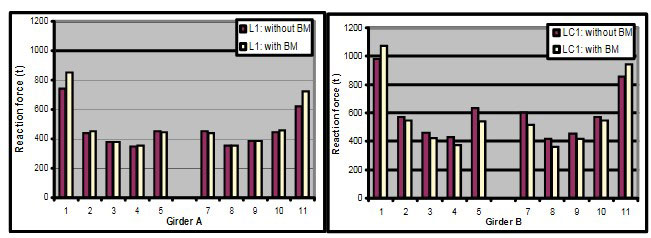
For LC2, the variation of the reaction force at GIR.A location is small except location 1 and 11, while the variation at GIR.B is relatively high due to hogging moment.
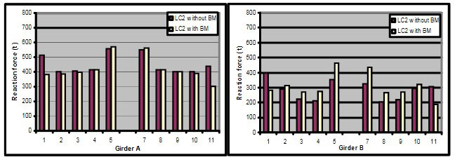
For LC3, the tendency of variation of the reaction force is similar to LC1. For location 1 where maximum reaction force is found, the increase of the case with sagging moment is found to be about 7 % compared to that of the case without sagging moment.

From the above facts, the following effects are observed:
- The effect of hull girder bending is significant with respect to reaction forces, especially at GIR.B, i. e., close to margin girder.
- The variation of reaction forces is found to be high at end supports and mid supports, while some locations of GIR.A have little variation.
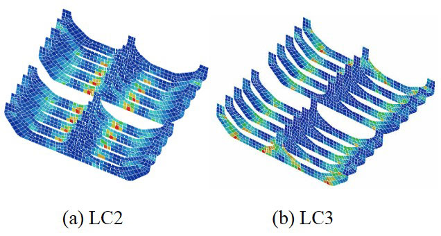
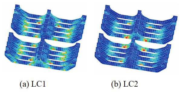
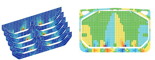
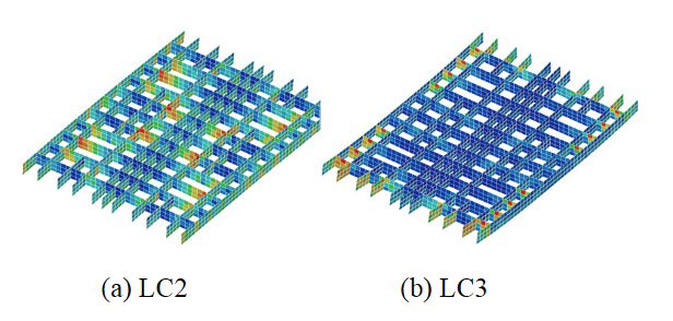
FE results indicate that the stress level in LC1 and LC3 is high in way of web frames close to end bulkhead, while the stress level in LC2 is high at mid web frames as shown in Figure 14. The strength of a cargo tank structure is accordingly evaluated based on the design acceptance criteria.
It is noted that the strength of transverse web frame structures of the cargo tank is mainly considered in this study as it is directly linked to reaction forces in way of supports.
3 Strength of Double Bottom Structure
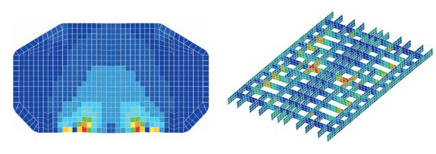
The deformation shape of the double bottom structure for LC2 and LC3 is illustrated in Figure 15.

As similar to cargo tank structure, high shear and equivalent von Mises stress is found at floors in way of mid hold in LC2 and at floors and girders adjacent to transverse bulkhead in LC3, respectively. By screening areas with high reaction force, the strength of the double bottom structure may be evaluated.
Transverse supports
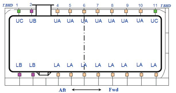
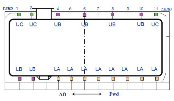
The transverse support is designed for the heeled condition in LC4 and transverse support arrangement of ship A is shown in Figure 16. The supports are practically divided into two or three types with different size and details based on the design loads determined by the calculated reaction force.
The sum of the calculated reaction forces over the transverse supports is checked and compared with the applied transverse load induced by maximum transverse acceleration as shown in Table 8.
Maximum transverse forces are found at keys close to end bulkheads and around the gas dome of deck and sump well of bottom while other locations are relatively moderate, as shown in Figure 17. Due to the difference of the structural stiffness of upper deck and double bottom structure, the reaction force is normally higher at lower transverse supports than at upper ones. It is also observed that upper part takes 32 % and lower part takes 68 % of the applied transverse load.
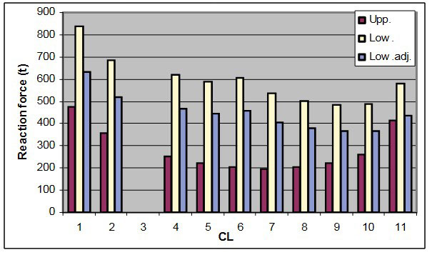
For the lower transverse support, the reaction forces obtained should however be adjusted by the fact that some of the transverse force is carried by the vertical supports due to the friction. In this case, the total transverse friction force is calculated by the total weight multiplied by minimum dynamic friction coefficient of 0,1. The resultant transverse force at all lower support is finally obtained by reducing the friction force corresponding to a ratio of 0,245 of the calculated transverse force. The design loads for the keys and supports are determined based on the calculated reaction force and is assumed to be as follows:
- Upper transverse support:
- Type UA 300 ton;
- Type UB 400 ton;
- Type UC 500 ton.
- Lower transverse support:
- Type LA 500 ton;
- Type LB 650 ton.
For hull structure, the strength of deck transverse girder is critical with respect to yield strength, especially the face plate of the girder. Based on the force distribution, the deck transverse girder located close to transverse bulkhead is normally reinforced compared to other locations.
Optimised support arrangements
The reaction force distribution in supports for ship A as obtained from cargo hold analyses was applied in order to find optimized support arrangement.
The change of a force distribution in supports after removing some of the supports with low utilization is observed. The magnitude and variation of reaction forces are compared with the allowable force to confirm the type of support at each location. In addition, the consequences in the cargo tank and the supporting double bottom structures are also considered.
Vertical supports
In this section, four cases with different support arrangement are reviewed and analysed.
1 Case 1
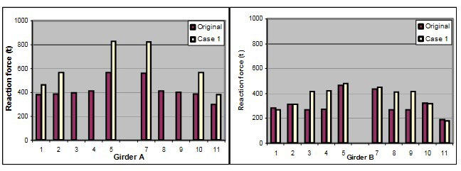
First attention is focused on GIR.A location with low reaction forces except end supports and mid supports with high reaction forces. Hence, eight vertical supports (Port & Starboard) are removed as shown in Figure 18.

The calculated reaction forces for case 1, shown in Table 9, are summarized. High increase of the reaction force in way of neighbouring supports of the removed supports is observed. However, there is little change for the maximum reaction force of 1 431 ton compared to that of original support arrangement showing 1 444 ton.
Figure 19 shows the variation of reaction forces after removing eight vertical supports compared to original support arrangement, especially for LC2 as it turns out the highest variation in mid location. The increase of reaction forces in way of neighbouring supports is about 45~55% due to redistribution of the applied vertical load.
Since the calculated reaction forces at location 5 and 7 of GIR.A exceed design load of 650 ton, the type of support should be changed into Type VB while other locations are kept as they are. For LC3, location 1 of GIR.A should also be changed into Type VC as the calculated reaction force slightly exceeds the design load of 1 100 ton. The change of the support type is shown in Figure 20.
The strength evaluation of a cargo tank and the supporting double bottom structure is focused on the locations with high increase of the reaction forces due to the removal of some supports.
For transverse web frames of the cargo tank, FE results indicate stress level is increased as high as reaction force increase as shown in Figure 21. Hence, scantling reinforcement of web frame is required to comply with acceptance criteria, especially for location 2 and 10 in LC1 and location 5 and 7 in LC2.
The highest stress in LC3 is normally found at web frame close to end bulkhead which is the most critical area. Due to increase in reaction force about 5 % at location 1 and 11 of GIR.A, the face plate of the web frame shall be reinforced. However, the strength of the web plate in question is found to be acceptable as stress increase is moderate and these areas have sufficient strength margin. Hence, LC3 is not considered to be very critical to the web frame.
For double bottom structures, FE results for design load conditions are generally found to be acceptable as the current structure has already strength margin. Hence, the influence on the double bottom structure is considered to be minor.
Based on the review of the reaction force distribution and stress level of the cargo tank and the double bottom structures, the support arrangement of the case 1 is considered to be efficient. However, some design changes of the support type and structural reinforcement are required to comply with design acceptance criteria due to higher reaction force in some of the supports.
2 Case 2
Similarly, eight vertical supports are removed, but to reduce high reaction force increase on the neighbouring supports every second support at GIR.A are removed. Instead, vertical supports of type VB are fitted at swash bulkhead position based on the experience of case 1.
Anti-pitching support is relocated at location 3 and combined with vertical support, as shown in Figure 22.
With the introduction of supports at swash bulkhead position, the reaction force is mainly redistributed into mid supports such as location 4, 6 and 8, as shown in Table 10. No change of support type is needed as the calculated reaction forces are less than allowable forces.
For web frame of the cargo tank, FE results indicate the stress is highly increased at location 4, 8 and swash bulkhead of GIR.A in LC2, which is found to be dominant, see Figure 23. The stress level for von Mises equivalent stress exceeds acceptance criteria at location 4 and 8 where scantling reinforcement of the web frame is required. The strength of the swash bulkhead is found to be on the limit of acceptance criteria.
The strength of double bottom structure is generally found to be acceptable with respect to acceptance criteria. However, the floor at swash bulkhead position has to be further reviewed with respect to shear strength capacity due to access opening.
Based on the review of reaction force distribution and stress level of the cargo tank and the double bottom structures, the support arrangement of the case 2 is considered to be efficient with a minimum of design changes and reinforcement since original design has same strength margin.
3 Case 3
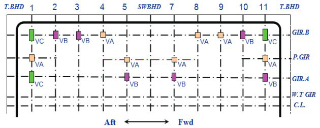
Vertical supports are rearranged, shown in Figure 24, focusing on mid and end supports where high reaction forces are found. One additional support is fitted at location 1 and 11 in the partial girder location in order to avoid high force concentration close to end bulkhead and to hopper area (GIR.B), and other supports at GIR.A location are removed. The support at location 5 and 7 of GIR.B is also removed as the neighbouring supports are found to be sufficient to take the applied load.
The calculated reaction forces for case 3 are summarized in Table 11. The tank loads are redistributed and high increase is observed at most of the supports while the maximum reaction force at location 1 is slightly reduced due to the additional support. Based on the obtained force, the support type is shown in Figure 24. As an alternative, the design load for the support need to be adjusted since the reaction force is relatively larger than originally assumed design load. The design load of Type VA is proposed to be increased to 750 ton.
FE results indicate that the current support arrangement causes a significant stress increase compared to original support arrangement. Figure 25 shows high stress increase at web frame at location 5 and 7 in LC2 and at location 1 and 11 in LC3. The scantling reinforcement of face plate and web plate should be considered with respect to yield strength.
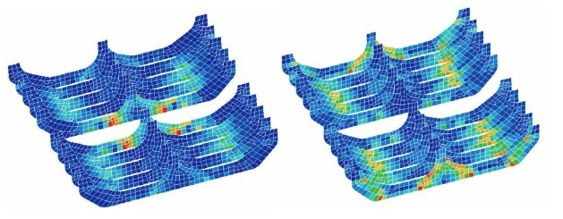
Double bottom structure is also checked both with respect to yield and buckling strength. LC2 is generally within the acceptance criteria although high stress is found in way of mid hold area as shown in Figure 26. However, the results of LC3 show the stress level at floors close to hopper girder require structural reinforcement.
4 Case 4
Based on the case 3 study, vertical supports are slightly rearranged in way of swash bulkhead as shown in Figure 27.

From the calculated reaction force, in Table 12, it is found that the reaction forces at GIR.B are slightly reduced due to the introduction of the support at location 5 and 7 of GIR.B, and the reaction force at swash bulkhead location is increased about 35~40% compared to case 3. The change of the type of support is shown in Figure 27.
It is found that LC2 gives the highest reaction force by 1081 ton in way of swash bulkhead location, which is almost two times compared to that of original support arrangement. The strength of the swash bulkhead of cargo tank is found to be critical with respect to yield strength as shown in Figure 28, and a local structural reinforcement is needed. Instead, due to reduced reaction force at location 1 and 11 of GIR.B, the scantling of cargo tank web frame in question may be reduced.
The stress response of the double bottom floor and girder in LC2, in Figure 28, showing high stress in way of swash bulkhead position to be reinforced with respect to yield.
The stress level at floor s close to hopper girder is relatively higher than that of original support arrangement, and need to be reviewed as well.
Transverse support
Based on the reaction force distribution in the original support arrangement, some supports with low reaction force in mid area are considered removed. In order to avoid high reaction force in the neighbouring supports, some every second support are removed in some areas, as shown in Figure 29.
Table 13 shows the calculated reaction forces in the keys at each location. The total transverse load is redistributed into the upper and lower keys and high variation is found at upper part while lower part has almost same result as the original case. Although the reaction force exceeds allowable force for some supports requiring that the type of support to be changed, it is considered to be an effective and optimised arrangement. The change of the type of support is presented in Figure 29. The design of the deck transverse girder need further to be reviewed with respect to possible reinforcement.
The possible reduction of transverse support is practically limited compared to vertical support arrangement due to the characteristic of the support arrangement.
Conclusion
The article describes a study on optimized and practical support arrangement of a cargo tank for Tank Type A LPG ships, emphasizing possible reduction in number of the cargo tank supports based on a force distribution as well as the strength of cargo tanks and the supporting double bottom structures.
Investigation of existing tank support arrangements shows high variation in terms of total number of supports. The design parameters, especially transverse web frame spacing and support arrangement have significant impact on the total number of supports. This may have significant benefits with respect to production, inspection and maintenance.
The effect of hull girder bending in view of a reaction force variation at different locations is investigated by global cargo hold analyses. Hull girder hogging increases the reaction force in way of mid supports and decreases it at supports close to end bulkhead, and vice versa for hull girder sagging.
The design load of the cargo tank supports are determined based on the calculated maximum reaction forces. In the detail design of each different type of support, the strength of wood and resin has to be carefully reviewed in addition to the strength of the steel structure.
Based on the case studies, the support arrangement of a cargo tank can be practically optimised and improved by evaluating the reaction force distribution obtained from finite element analysis. When removing some of the supports with low utilization the applied load is redistributed into the neighbouring supports, and consequently will increase the stress level of the cargo tank and the supporting double bottom structure. This will lead to reinforcement and redistribution of scantlings.
In order to do optimization of support arrangements, comprehensive integrated structural analyses comprising both cargo tank and hull structure are necessary. This analysis shall be based on IGC code, applicable rules and procedures.