The radio telex technique is built upon experience gathered from the design of the land telex network. By means of radio telex, a ship station is given the possibility of sending messages from the ship to the international telex network.
The abbreviation NBDP is often used in radio terminology. It stands for Narrow Band Direct Printing.
The System
When a ship has traffic on hand, it will establish a radio telex connection on the radio frequencies assigned for telex purpose. These frequencies are listed in the ITU publication “List of Coast Stations”.
The ship station consists of a transmitter, a receiver, a special adapter called a MODEM (MOdulator-DEModulator), and a teleprinter.
Corresponding equipment can be found on land (Coast stations), and in addition, data bases are used for handling large quantities of traffic.
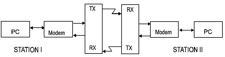
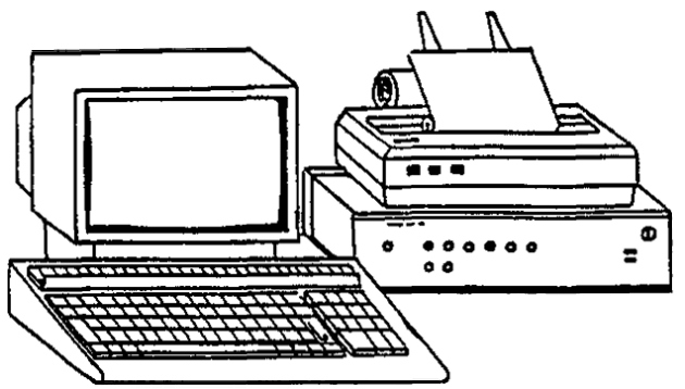
Modern telex equipment usually consists of a keyboard connected to a screen (e. g. a laptop PC), a hard copy printer, a modem, a Basic transmitters and receivers in shippingtransmitter and a receiver. The system allows messages to be edited and stored.
The Modem
The modem has a very important function in the radio telex system. Without a modem, the system would not be able to function. The modem takes care of the adjustment of signals from the text editing equipment to the radio transmitter, and vice versa.
The modem also has some additional functions, such as:
- Automatic error correction (ARQ).
- Changing the transmitting direction (between transmission and reception).
- Programming selective call numbers.
- Calling.
The modem is also fitted with LED’s (light emitting diodes) indicating the different stages of the TELEX (Narrow Band Direct Printing – NBDP) Proceduresradio telex communication.
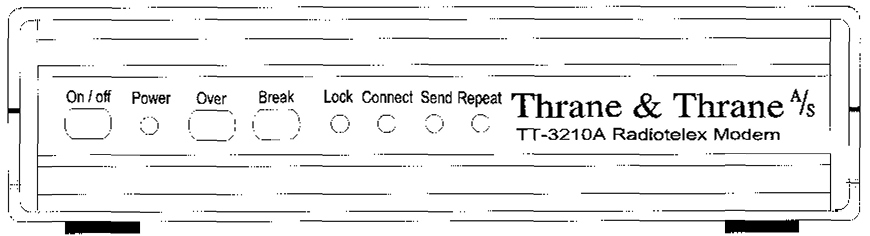
A typical telex modem is shown above. When the telex communication is established, the different categories of traffic status can be supervised.
Control switches/LED’s
On/off: Power supply switch. If loss of mains, an internal battery will ensure that stored messages in memory are not lost.
Over: If the station is in transmitting mode, a change of “transmission direction” will occur if the over button is pressed for a short time. A continuous push of at least 2,5 seconds will cause an immediate change in transmission direction.
Break: Close down the telex connection.
Indicating lamps/LED’s
Lock: The modem is locked to another station.
The modem can be locked for the following reasons:
- The modem has established a connection on ARQ.
- The modem is receiving an FEC (Forward Error Correction).
- The modem is receiving a “Free Signal”.
Power: Indicates that the power has been switched on.
Connect: The modem is connected to another station, either an ARQ connection or an FEC.
Send: Data transmission is in progress. The LED will start flashing when transmission has finished.
Repeat: Errors in data received or transmitted.
Modulation
In Importance of Reliable Marine Communications and Empowering Maritime Industrymaritime communications the upper side band (USB) is used for all kinds of communication.
Read also: DSC (Digital Selective Calling) Procedures for VHF – MF and HF
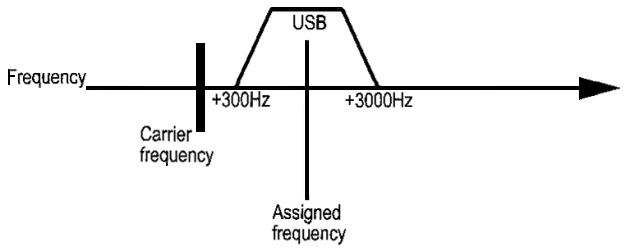
A voice channel (telephony) is modulated in the frequency range from 300 Hz up to 3 000 Hz.
On a telex channel, the centre frequency is placed in the middle of the upper side band at 1 500 Hz.
The method of modulation used by radio telex is called FREQUENCY SHIFT KEYING (FSK).
The technical term in use is FIB. This term is used in the ITU publication “List of Coast Stations” to characterize all radio telex channels.
Frequency shift keying is achieved when the Transmission of Urgency and Safety Signals from a Vesseltransmitted signal alternates between two different frequencies. These two frequencies are referred to as the SPACE and the MARK frequency.
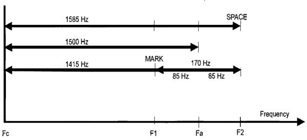
When studying the figure above, one can see that the frequencies F1 and F2 are equally spaced from the Fa frequency, which is known as the “ASSIGNED FREQUENCY”.
The assigned frequency is normally located 1 500 Hz over the carrier frequency (Fc).
In some equipment the assigned frequency can be 1 700 Hz, or 1 900 Hz over the carrier frequency.
In modem transceivers, the transmitter and the receiver frequency are set to the assigned frequency, and the equipment will automatically shift to carrier frequency in telex mode. In older equipment, the carrier frequency must be set manually to 1 500, 1 700 or 1 900 Hz under the assigned frequency.
As far as telex mode (FIB) is concerned, the frequencies listed in the channel list or in the “List of Coast Stations” are always the assigned frequency.
ARQ
Ordinary land telex uses an “alphabet” consisting of 5 characters. ARQ-systems designed for radio telex use an “alphabet” consisting of 7 characters.
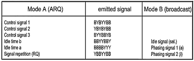
ARQ (AUTOMATIC RETRANSMISSION REQUEST) is used in two-way communication. The ARQ unit is able to ensure that every character received has the correct proportion of 4 to 3.
The table below shows that every character consists of 4Bs and 3Ys, where B is the highest transmitted frequency (SPACE), and Y is the lowest transmitted frequency (MARK).
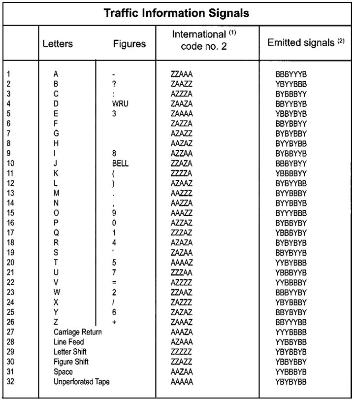
The ARQ unit ensures that all characters received, have the proportion of 4 to 3 between Space and Mark. If the proportion is wrong, the ARQ will request a repetition.
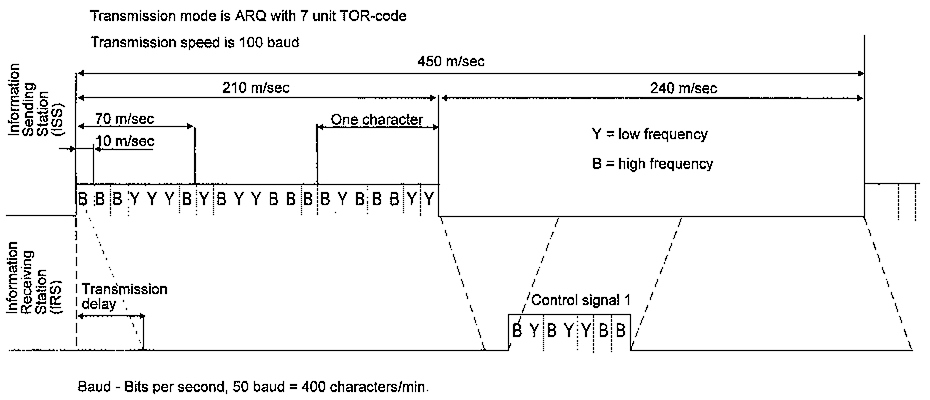
On radio telex, blocks consisting of 3 characters are transmitted in a sequence, and, in order to be recognized, all blocks must have the proportion of 4 to 3 between Space and Mark. If the block is approved (3 characters), the ARQ will transmit a recognition to the transmitting station, and the next block will be transmitted. When an error is received, the ARQ will ask for repetition.
On radio telex it is possible to repeat a block up to 32 times.
FEC
Broadcasting is another way of transmitting radio telex communications. This system is used for GMDSS Distress and Safety Communicationsdistress communication, NAVTEX, traffic lists, news bulletins etc. Error correction is achieved by using Forward Error Correction, which stands for “FORWARD ERROR CORRECTION”. Every character is transmitted twice, with an interval of 280 milliseconds between the direct and the repeated transmission. If the character is received garbled, it will be printed out as a star, or only a space, at the receiving station. In selective-Forward Error Correction, the transmitted signals are coded, thus allowing only the called station to receive the signals correctly.
Below is an example of a NAVTEX message received in Forward Error Correction mode. Note that garbled characters are printed out as a star.
DOVER STRA*IT. CABLE LAYING OPERATIONS
BY CABL*SHIP GUILO VERNE
CROSSING TRAFFIC SEPARATION SCHEME
BETWEEN 51-15N 02-32E AND ST.
MARGARETS BAY (51-09N 01-32E).
2. GUARDSHIP IN ATTENDANCE.
3. DETAILS FROM CHANNEL NAVIGATION
INFORMATION SERVICE
VHF CHANNEL 11.
4. CAUTION ADVISED.
NNNN
SELFEC
SELFEC, SELECTIVE FORWARD ERROR CORRECTION, is another radio telex broadcasting method. SELFEC operation is similar to Forward Error Correction operation except that the transmission is designed to send messages to one station only. The operator simply uses the selcall number of the receiving station, and this activates the modem and prepares it to receive a SELFEC message.
Maritex
Earlier we have learned that coast stations handle large amounts of traffic. On shore, computerized traffic handling is common, and coast stations often use data bases to relay traffic to ship stations. Maritex is a global, computerized and automatic network for maritime radio telex.
The Maritex system is operated by the Nordic countries, and the Swedish company Telia Mobitel AB acts as Executive Company, responsible for technical operation and traffic management.
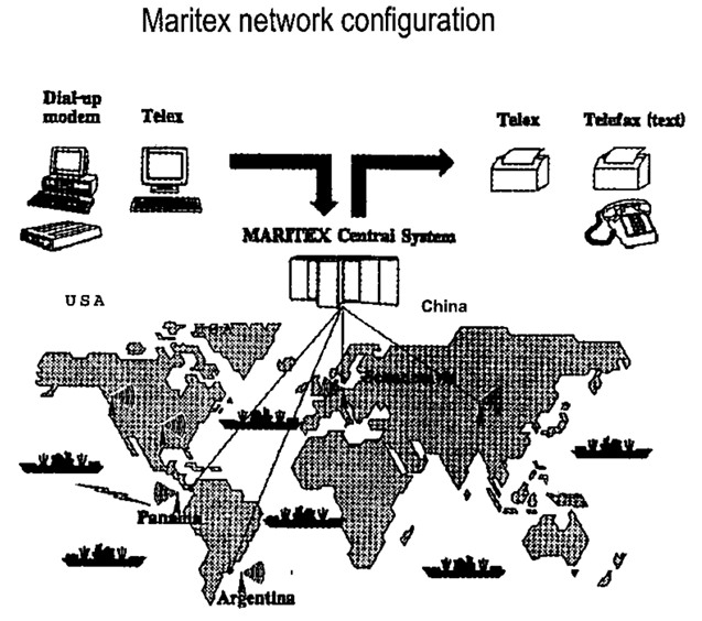
Maritex network design in brief
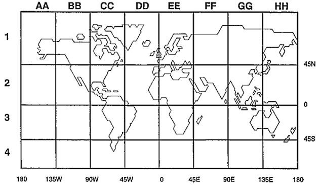
Let us consider the figure on the next page, showing an overview of the Maritex system with its headquarters in Gothenburg. The Central computer system is located in Gothenburg and acts as the “heart” of the Maritex system. To obtain maximum security, the system is run with a high technology dual computer configuration. The central computer system is in full remote control of transmitters and receivers and ARQ modems, in stalled at sub-stations in Scandinavia, USA, Panama, Argentina and China.
By such an arrangement, Maritex has managed to bypass the laws of nature that restrict performance on MF/HF bands. The Central system in Gothenburg does all the message switching, and coordinates all sub-station resources. Seen from a ship, all radio channels behave identically regardless of geographical location. From land, the system works identically, and subscribers only need to know the Swedish telex number for the ship they want to address traffic to.
Traffic shore-to-ship
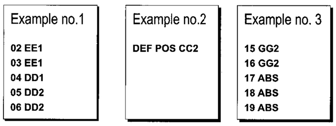
All Maritex ships registered in the system are assigned ordinary 5-digit land telex numbers. This allows all land based subscribers worldwide to use normal procedures for international telex traffic when routing traffic to a Maritex vessel. When the Maritex system receives a telex from ashore, the system will immediately generate a series of selective calls on anumber of predetermined radio telex channels. These radio telex channels are pre-set in shipbom equipment for continuous automatic scanning. A call which is successfully received, will activate the equipment on board, and the message will be printed out or stored without the presence of a radio operator. Maritex ships transmit regular position reports to the Central system. Guided by the ships’ position reports, Maritex will use the most suitable sub-station and transmitting-receiving antenna, to obtain the best possible circuit quality.
Traffic ship-to-shore
When a Maritex channel is available for a ship-to-shore call, this is indicated by “Free-Signal” emission from the Central system. The “Free-signal” is detected and recognized by the ARQ-modem, providing permission to start the transmission. In this way the Maritex system prevents interference with on-going traffic from other ships. The radio-operator on board can manually initiate a call by a simple keyboard command, or he can choose an automatically conducted call via the ship’s terminal. In the ship-to-shore direction, Maritex offers many different services which are described in the Maritex Traffic Manual.
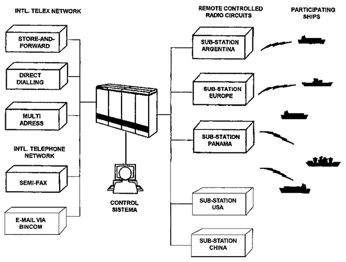
Store and forward – Store-and-forvard telex (TLX) is stored in the Central system, and delivered to the final destination after a few minutes.
Direct dialling – The DIRTLX facility provides direct contact with subscriber (handshake) and can also be used for dialogue.
It will be interesting: Loran-C Charts and Related Information
Multi-address – The ship has one standard message to several different subscribers. Through a single radio transmission the ship can order copies to be sent to an unlimited number of subscribers.
Semi fax – The Semi Fax facility enables the ship to order a message to be transmitted as a fax from the Central system to a destination ashore, using the international telephone network.
Bincom E-MAIL – Messages via BINCOM Electronic Mail, ship-to-shore and shore-to-ship.


- Global Maritime Distress and Safety System: IMO 1987.
- Manual for use by The Maritime Mobile and Maritime Mobile- Satellite Services: ITU 1992.
- Radio Regulations 1-2-3: ITU 1990.
- Manual for Norwegian Mobile Radiotelephone Stations: The Norwegian Telecom 1992.
- Modem Electronic Communication: Gary M. Miller 1978.
- Brochures and data sheets from manufacturers of GMDSS Equipment.
- Inmarsat: Inmarsat-A User’s Manual, Inmarsat-C User’s Manual.
- Nodposisjonering: Bjomar Augdal, 1992.
- Skipsantenner: Bjomar Augdal 1991.
- COSPAS-SARSAT Secretariat: COSPAS-SARSAT System Data Documents.
- Admiralty List of Radio Signals.