Effective communication systems rely on the fundamental interplay between three key components: Marine Radio Receivers, Transmitters, and Modulation. This article delves into the core functionalities of each, providing a foundational understanding for further exploration of communication principles.
We will examine the basic operation of transmitters, responsible for generating and transmitting signals. Understanding this is important for anyone who wants to understand the basic mechanisms that make our modern world of communication technology possible.
Basic Transmitter
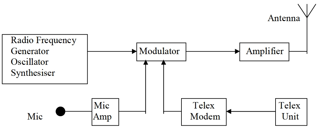
The radio frequency generator produces the carrier, i. e., the frequency on which we wish to transmit.
The modulator is used to combine the information signals from the microphone or the telex with the carrier. The type of modulation may be amplitude (AM), frequency (FM) or phase (PM). This modulated signal is then amplified within the transmitter and fed to the antenna.
The antenna requires tuning to carrier frequency so that it will radiate efficiently. Antennas made from wire elements radiate most efficiently when they are one quarter of a wavelength long.
It is not practicable on board ships to install an antenna which is physically the ideal length over all of the MF or HF bands. However, the electrical length of the antenna can be lengthened or shortened with respect to its physical length by the introduction of extra radio – frequency circuit elements, inductors and capacitors, in an Antenna Tuning Unit (ATU).
In most modern equipment, this is achieved automatically by pressing the “Tune” button before actual transmission. A signal strength meter which measures antenna current gives a visual indication of transmission. Most equipment allows for Manual tuning mode on 2 182 kHz in case the automatic tuning fails. Individual manufacturer’s manuals should be consulted for further details. The default 2 182 kHz setting need only be carried out upon installation or if your antenna is moved or changed
Basic Receiver
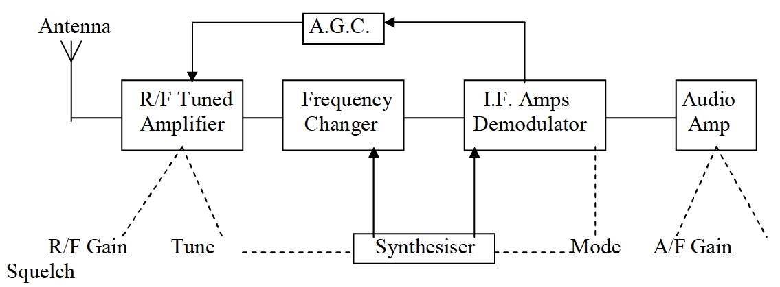
The wanted signal is received by tuning the input to the receiver to the wanted frequency.
Received signals vary greatly in strength due to a number or factors, e. g.:
(a) A local transmitter radiating high or low power.
(b) A distant station radiating high or medium power.
(c) Variations in the ionosphere which may affect signals on MF at night or on HF at any time – polarisation fading.
(d) Simultaneous reception by ground and sky waves on MF at night which may constantly vary in strength or phase and interact with each other – interference fading.
(e) On the HF bands, signals can reach the receiver having taken different paths, again causing interference fading.
The radio frequency “Gain” or “Sensitivity” control allows manual adjustment of the input amplifier so as to set up the gain to suit conditions. Continual adjustment of the gain control may be necessary if fading occurs, in which case the Automatic Gain Control (AGC) can be switched, thereby taking over from manual control, i. e., the AGC holds the output at a nearly constant level even though the input may fluctuate widely.
Most GMDSS MF/HF receivers can be tuned into the wanted signal by more than one method, i. e., if paired HF frequencies are required you can simply select the ITU channel number.
Alternatively, the actual frequency can be keyed in. If it becomes necessary to re-tune to a station only a few kilohertz away, then the up/down “Tune Arrows” can be used.
Read also: General Provisions, Rules and Requirements for Safe Carriages of Cargoes
Fine tuning is sometimes necessary, especially when it is required to “clarify” reception of single–sideband (SSB) speech transmissions (i. e., mode of emission = J3E). Selection of the “clarifier” allows tuning down to an accuracy of 10 Hz but it is normally used by listening to the output and tuning to the speech rathen than to the actual frequency. The “Volume” or “A. F. Gain” control simply varies the amount of signal passing to the loudspeaker, whilst the “squelch” or “mute” control turns off the loudspeaker when no signals are being received.
The setting of the “mode” control is dependant upon the type of modulated signal being received, i. e., on the mode of emission (see Article 4 of the ITU Manual for use by the Maritime Mobile and Maritime Mobile – Satellite Service).
Modulation
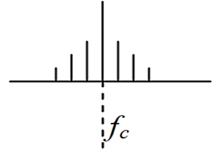
Modulation is the mechanism whereby a radio-frequency carrier wave is used for the transmission of information. In the maritime context the type of information carried is mainly speech or data. The information modulated on to the carrier wave appears as additional frequencies, around the carrier frequency, known as sidebands.
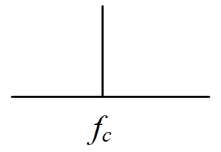
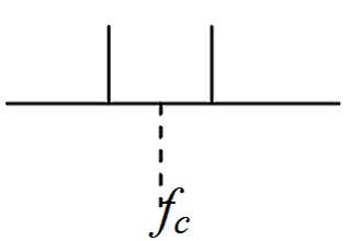
The simplest form of communication is Morse code, sent by switching the carrier on and off in a sequence of “dots” and “dashes”. This type of transmission is known as mode of emission A1A, and there are no information sidebands as such; the information content is determined purely by the keying sequence applied to the transmitter.
Although very efficient in terms of the range achieved for a given transmitter power, the rate at which information can be sent is relatively low: 20 to 25 words per minute is a good commercial rate for a ship using radiotelegraphy. Morse code can also be sent using an audio tone, keyed on and off, to modulate the carrier wave, e. g., modes of emission A2A and H2A.
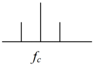
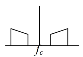
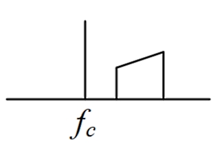
Most communications on MF and HF now use single-sideband (SSB) techniques for both speech and NBDP/telex transmissions. In a double-sideband (DSB) transmission more than two thirds of the transmitter output power is contained in the carrier, which contains no useful signal information. Also, the upper and lower sidebands contain the same information.
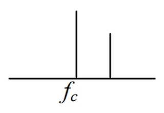
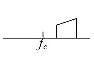
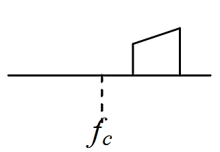
By eliminating the duplicated information in the lower sideband, along with the carrier, the transmitter efficiency is greatly increased. In effect, the space taken up within the frequency band is reduced and so more stations can transmit.
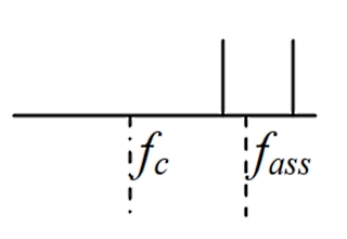
- fc = carrier frequency;
- fass = assigned frequency – defined as the centre of the frequency band assigned to a station.
A narrower bandwidth for the transmitted signal means that less noise and interference (both man-made and natural) is apparent at the receiver, resulting in a relatively smaller masking effect on the wanted transmission. Also, the transmitter power is used more efficiently. The net effect is that, for the same transmitter power, the effective range of a transmission will be greatly extended by using a narrow-bandwidth method of modulation such as SSB.
After full implementation of the GMDSS, all maritime MF/HF voice communication will use the J3E mode of emission, i. e., SSB, suppressed carrier. At present, transmissions on 2 182 kHz may still use the H3E or R3E modes of emission, i. e., single-sideband with full or reduced carrier, respectively. The bandwidth of a J3E mode voice transmission is 2,8 kHz (note that if the assigned frequency of a J3E transmission is quoted it will be 1,4 kHz above the carrier frequency).
DSB (A3E) transmissions are used by LFMF/HF broadcasting stations with a bandwidth of 9 – 20 kHz, depending on local standards. Some broadcasting stations incorporate useful weather forecasts in their programme output.
Although a NBDP/telex transmission is essentially a coded stream of data, the standard method of transmission at MF/HF is to transmit the Exploring Radio Paths, Spectrum, and Propagation Mechanismstelex signal codes as a sequence of two audio tones. The ITU recommends that a frequency shift of 170 Hz about a centre frequency of 1 700 Hz is used to send the “mark” and “space” tones, i. e., mark = 1 615 Hz and space = 1 785 Hz.
NBDP/telex can be transmitted using SSB modulation, mode of emission J2B. The assigned frequency of the transmission is defined, in this case, as the centre frequency between the mark and space sideband frequencies, i. e., 1 700 Hz above the carrier frequency. A type of frequency modulation, “frequency shift keying” (FSK), can also be used for NBDP/telex, in which case the transmitted frequency shifts by ±85 Hz about the carrier frequency. This is described as mode of emission F1B; note that the assigned frequency and the carrier frequency are the same in F1B mode transmissions.
Because the two sideband frequencies are 85 Hz above and below the J2B mode assigned frequency or the F1B mode assigned/carrier frequency, it can be seen that the modes of emission J2B and F1B are essentially identical for two-tone NBDP/telex transmissions. However, it is still essential to check which frequency (assigned or carrier) and which mode (J2B or F1B) has been quoted. If either J2B or F1B mode is not available on the equipment being used, then it may be necessary to offset the tuning by 1 700 Hz from the quoted frequency to compensate for the difference between the J2B assigned frequency and the F1B assigned carrier frequency. The manufacturer’s handbook should be consulted to confirm how the tuning and mode controls interact.
At VHF frequency modulation (F3E mode) and phase modulation (G3E mode) are used for speech. The ITU List of Coast Stations shows some VHF channels as F3E and others as G3E but, as far as the operator is concerned, there is no difference because a change in frequency of the carrier also results in a corresponding change in the phase of the carrier, and vice versa.
Depending on the type of equipment in use, it may also be necessary to optimize the “Bandwidth” control to match the mode of emission. Many modern receivers set the bandwidth automatically in line with the
If the bandwidth is set too wide for the mode of emission then more noise will be apparent. Also, greater interference from unwanted stations an adjacent frequencies will be received, thus degrading the reception quality of the wanted station.
Frequency/phase modulation generates several sidebands above and below the carrier for each modulating frequency, depending on the depth of modulation. Thus the occupied channel bandwidth for a frequency – modulated transmission is wider than needed for the equivalent J3E amplitude-modulated transmission (2,8 kHz).
It will be interesting: Preparation of the Cargo Spaces, Stowage and Securing of Cargoes on the Vessel
However, frequency – modulated transmissions provide better quality reception because the demodulation process can reject weak interfering transmissions as well as substantial amounts of amplitude – varying interference (e. g., from electrical storms, electrical machinery and spark ignition systems).
In satellite systems several complex analogue and digital modulation methods are used but, being automated systems, the technicalities involved are hidden from the operator.

