An underwater shock in the vicinity of a hydrocarbon carrying ship is a serious risk.
This article covers info about underwater detonation, effect of underwater explosion, phenomena associated with underwater explosion and etc.
Underwater Explosion (UNDEX)
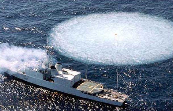
Underwater Explosion create shock waves in a similar manner to explosions in air.
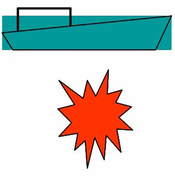
Gas Bubble and Shock Wave from an Underwater Explosion.
Ship survivability depends on:
- susceptibility,
- vulnerability,
- and recoverability.
Effect of Underwater Explosion (Shock wave, Surface cut-off, Cavitation, Bubble formation and Plume)
Detonation of high explosive charges, irrespective of their type and location, cause high overpressure.
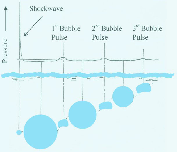
Migration Pathway, Pressure Pulse and Bubble Oscillation
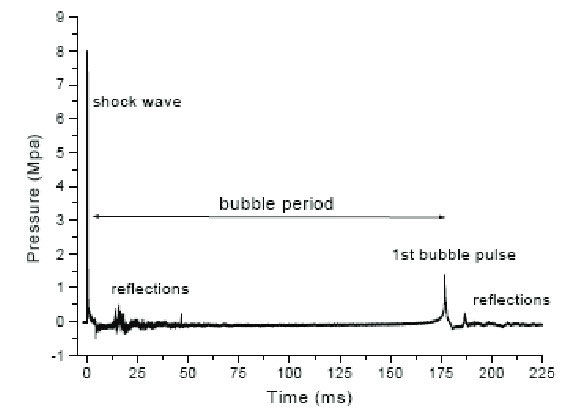
Bubble pulses are generated by the oscillation of the gas bubble created by the UNDEX. The peak pressure of the first bubble pulse is about 10-20 % of the shock wave. The first high pressure in the gas sphere is significantly reduced after the primary part of the shock wave has been transmitted.
It can be said that about half of the energy of the explosion is transmitted in the shock wave.
Phenomena Associated with Underwater Explosion
UNDEX Phenomena
The Effect of UNDEX on Surface Vessels
Underwater Blast Effects
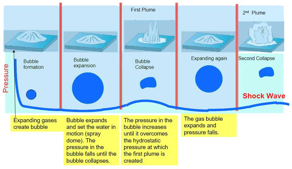
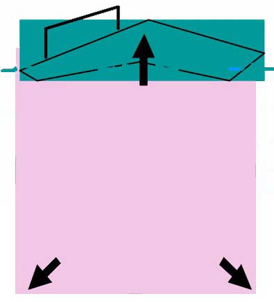
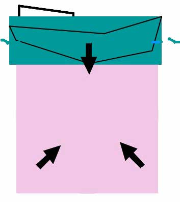
Cavity (Bubble) of High pressure gas and water vapour:
- Hydrostatic Pressure Fluctuations.
- Expansion and Compression.
Energy Losses:
- 90 % of the bubble’s energy dissipates on 1st expansion.
- Acoustic and heat radiation.
Multiple Shock Waves:
- Due to pulsating bubble as it rises.
- Proximity of boundaries (bottom and surface).
Based on the location of the charge with respect to the sea floor and the free surface, a vessel may experience a combination of different pressure waves, due to different propagation paths.
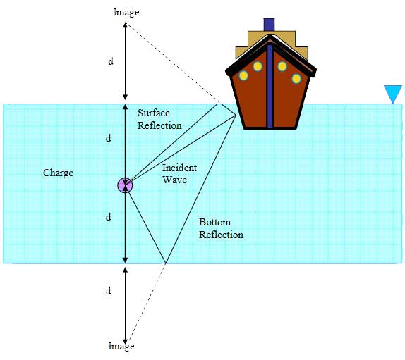
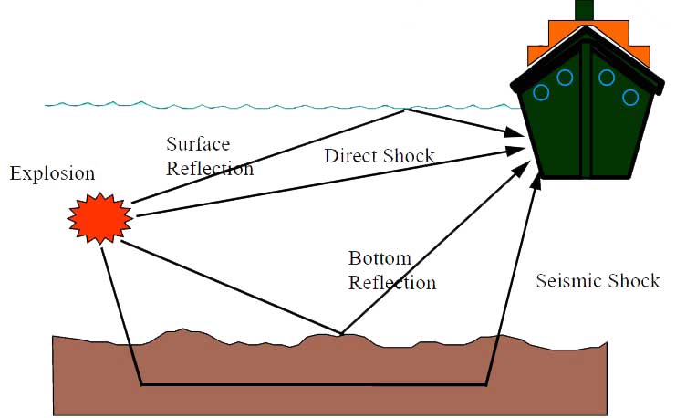
- Direct shock.
- Free-surface reflection.
- Bottom reflection.
- Bottom refraction (not shown).
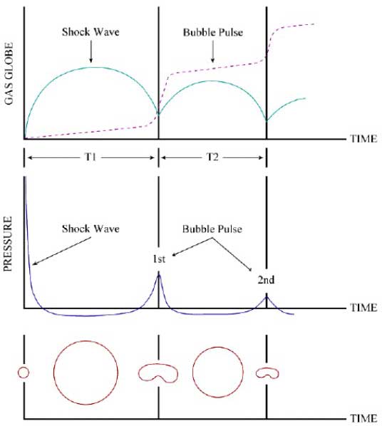
UNDEX Pulse, up to the Collapse of First Bubble
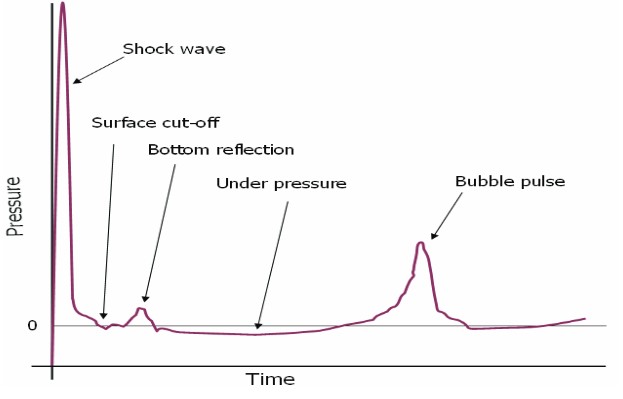
The resultant pressure-time history is the time-phased super positioning of the direct, surface and bottom reflection.
Surface Cut-off
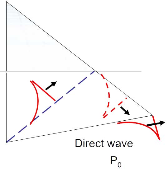
surface Reflection
The Bulk and Local Cavitation
Cavitation occurs when a region of negative absolute pressure present in the water. This negative pressure causes the tensile force in the water, since the water cannot sustain this force, cavitation or separation is formed.
Underwater Explosion Event
Bulk Cavitation
Local Cavitation
When fluid-structure interaction occurs, the total pressure throughout the ship’s hull turns out to be negative. Since the water can not sustain tension, the water pressure decreases the vapour pressure, and then local cavitation occurs.
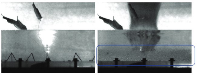
Right: Cavitation bubbles can be seen near the
bottom surface of the container
Explosive detonations which occur underwater create shock waves in a similar manner to explosions in air. Most Underwater Shock, Effects and Risks for Hydrocarbon Carrying Shipsunderwater explosion are not seen on the surface due to the elastic properties as well as the depth of water and the size of the net explosive weight.
Quantifying UNDEX Loads
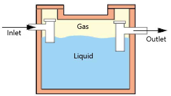
Interior and Exterior Problem
The structure (tank) surrounds the non structural fields: liquid and gas.
The structure (submarine hull) is surrounded by the non structural fields, liquid in this case.
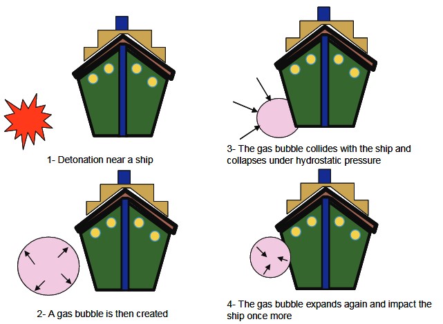
Possible Sources of Damage and Three Typical Scenarios
Effect of Proximity of Detonation
The gas bubble created by the explosion can cause violent hull vibrations known as “whipping”.
The charge detonates in contact with the hull. The explosive effect is directed inwards due to the pressure of the surrounding water.
Effect of UNDEX on surface ships
Testing for Proving a Design

Use of Commercial Software for UNDEX
Commercial Software for UNDEX
ABAQUS capabilities for UNDEX (underwater explosion analysis) are integrated within the coupled fluid-solid interaction capability. Transient explosion simulations are generally handled in ABAQUS/Explicit, using specialized infinite boundary conditions and incident wave loading options.
ANSYS Underwater Shock Modules are used for many types of shocks, e. g. non-contact underwater shocks, from mines or other sources.
LS-DYNA is extensively used to simulate impacts on structures from drop tests, underwater shock, explosions or high-velocity impacts.
Combined Model of Ship and Fluid
The full history depends on the size and depth of charge and a vessel may not experience a complete sequence.
Interior problem. Sloshing of liquid:
Effect of Strong Vibration on Safety Critical equipments
High acceleration levels may cause a component malfunction if resonance frequencies of its constituent elements are excited. These components will not suffer catastrophic failure during vibration; they just will not operate as intended.
Concluding remark
- Underwater explosions have a number of effects on a surface vessel.
- An intelligent solution does not start with adding more materials.
- Commercially available software can be used to obtain an optimal solution.
- Using ABAQUS for UNDEX is outlined in the article.
Surface based fluid-structure interaction, master and slave surface concept is used
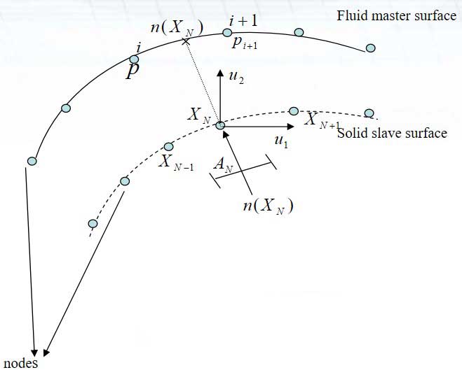
Shape functions: first order, 4 node linear tetrahedron element, g, h, r – local coordinates.
Contribution of a slave node to the coupling term in acoustic equation.
Contribution of a slave node to the coupling term in structural equation.
Deriving discretized finite element equations
| Deriving discretized finite element equations | ||
|---|---|---|
| Equations 1 & 2 define variational problem for coupled fields um and p | ||
| Interpolation functions in fluid p = HPpp P is no. of pressure nodes P, Q pressure DOF δp = HPδpP | Interpolation functions in structure um = NNuN N is no. of displacement DOF N, M displacement DOF δum = NNδuN | |
| Substituting interpolation functions in eq n. 1 & 2 | ||
Result of formulas a and b – coupled fluid-structure equations.
Finite element equations Contd…
- Eqn’s (a) & (b) couple total pressure in the fluid to the displacements in the structure.
- Matrix Sfs is defined over all the interacting fluid and solid surfaces.
p = pI+ps, in eqn (a) & (b)
where:
- – unknown calculated from above eqn.
- – known from incident Pressure wave equations.
The above 2 eqns are solved together with ps unknown variable.
- Radiation Boundary Condition.
- Pressure release boundary condition, p = 0.
The boundary traction term is given by:
Where:
- ρf – density of fluid,
- Kf – bulk modulus of fluid.
| Geometry | f | β |
|---|---|---|
| Plane | 1 | 0 |
| Cylindrical | 1 | 1/2*r |
| Spherical | 1 | 1/r |
Pressure distribution on structure
Where:
- хo = standoff point;
- хs = source point;
- хj = spatial point on structure;
- pI(xj, t) = incident pressure;
- pх(xj) = pressure due to spatial variation;
- co = wave speed in fluid.
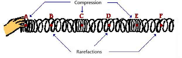
A longitudinal wave is a wave in which the particles of the medium are displaced in a direction parallel to the direction of energy transport. A longitudinal wave can be created in a slinky if the slinky is stretched out horizontally and the end coil is vibrated back-and-forth in a horizontal direction. If a snap-shot of such a longitudinal wave could be taken so as to freeze the shape of the slinky in time, then it would look like the above diagram.