An underwater explosion in the vicinity of a hydrocarbon carrying ship is a serious risk. Such risks are gaining importance as the security of workers, ports and energy supply are coming to the forefront. Ship could suffer local damage due to this effect. Strong shock waves could also disable electronic equipment on board even if they do no cause obvious structural damage.
- Summary
- Nomenclature
- Introduction
- Undex phenomenon
- Cavitation
- Bulk cavitation
- Local cavitation
- Effect of UNDEX on surface ships
- Shock damage
- Bubble pulse and collapse
- Surface cut-off damage
- Bottom reflection
- Modelling of ship and fluid
- Ship modelling
- Fluid modelling
- Modelling incident wave loading
- The fluid and ship interaction
- Surface based interaction
- Conclusions
- Acknowledgements
Summary
This article reviews the open literature on estimating shock loading and brings together elements which are relevant to the design of ships, considering accessibility and practicality of the approach. This article also provides a review of the response of vessels to underwater shock loading, with the emphasis placed on ways and means of evaluating and mitigating the effect of underwater explosion. Finally, the use of commercially available finite element packages for the dynamic response analysis of ships subjected to underwater explosion is discussed in some depth and an example is presented.
Nomenclature
- DAA – Doubly Asymptotic Approximations.
- UNDEX – Underwater Explosion.
- FSI – fluid–structure interaction.
- ac – the radius of the spherical charge.
- c0 – wave speed in the fluid.
- f(τ) – exponential decay term.
- pI – incident shock pressure wave.
- pS – scattered pressure wave.
- P(R, τ) – pressure time history.
- px(xj) – spatial variation at a point, Eq. 6.
- R – distance from the centre of the explosive.
- A and B – constants; see Table 1.
- Cs – structural damping matrix.
- Cf – fluid damping matrix.
- Ks – structural stiffness matrix.
- Mf – mass of fluid.
- Ms – structural mass.
- Sfs – the transformation matrix.
- x0 – standoff point.
- xs – specified source point.
- xj – a point of the structure.
- u – structural displacements.
- τj – “retarded time”.
| Table 1. Material constants for explosion loading | ||||
|---|---|---|---|---|
| Charge | Pc, GPa | vc, m/s | A | B |
| TNT (1,52 g/cc) | 1,42 | 992 | 0,13 | 0,18 |
| TNT (1,60 g/cc) | 1,67 | 1 010 | 0,18 | 0,185 |
Introduction
This article discus the shock loading due to underwater explosion (UNDEX) on surface ships (Figure 1). It also explains the use of commercially available software packages for simulating whole-ship response in underwater explosion environments. Such analysis typically leads to very large structure and fluid models. Most simulations have employed finite-element (FE) discretization of the structure, whether a surface ship or a submersible. For the latter at moderate to deep depths, the fluid–structure interaction (FSI) is typically handled with boundary elements, often employing a doubly asymptotic approximation, which is basically an acoustic treatment. However, for a surface ship or a submersible at shallow depth, the occurrence of fluid cavitation requires different treatment, and often finite-element discretization of a fluid is preferred. This reflects the localized nature of cavitation, for which finite-element modelling is more suitable. The transient solution to this problem class can be discontinuous in space and time due to the presence of discontinuous wave fronts and cavitation. Over the years, numerical simulations have been developed to accurately capture the fluid structure interaction between the structure and its surrounding fluid medium due to underwater explosion.
In the past, the response of surface structures was determined by physical testing. Physical testing for an underwater explosion is an expensive process that can cause damage to the environment and crew. Computational methods can effectively replace the experimental procedures for commercial floaters. Although demand on naval vessels is more rigorous, computational methods can also be used to reduce the amount of physical tests required.
Kwon and Cunningham coupled an explicit finite element analysis code, DYNA3D, and a boundary element code based on Doubly Asymptotic Approximation (DAA), Underwater Shock Analysis (USA). McCoy and Sun combined the finite element package ABAQUS and a fluid-structure interaction code based on the DAA to solve an underwater explosion analysis of a composite cylinder. Cichocki, Adamczyk, and Ruchwa have performed extensive research to obtain an UNDEX response of simple structures and have implemented entire fluid-structure interaction phenomenon, pressure wave distribution, and the radiation boundary conditions into the commercial finite element package ABAQUS.
Read also: How to Prevent Fire and Explosion or How to Minimize Effects of it
ABAQUS, ANSYS, MSC-Dytran and LS-DYNA capabilities for UNDEX are integrated within the coupled fluid-solid interaction capability, which is also used for structural acoustics. Transient underwater explosion simulations are generally handled, using specialised infinite boundary conditions and incident wave loading options. Though in what follows ABAQUS is used as a vehicle to explain the methodology, any of the above software can effectively be used (and has been used) for this purpose.
Undex phenomenon
When an underwater explosion occurs, the solid explosive material (such as TNT, etc.) suddenly reacts, leaving behind high temperature and pressure of gaseous products. An initial wave of compression is produced due to a sudden discontinuity of pressure which can reach a peak pressure of 1,4×10⁴ MPa see Figure 2.
This steep fronted wave known as a “shock wave” propagates rapidly outward at a speed several times the speed of sound in water and roughly decays exponentially. The velocity of the shock wave decreases such that at approximately 10 times the explosive charge radius, the disturbance is essentially travelling at the acoustic velocity in water, 1 550 m/sec.
In most applications, water is considered a homogeneous and incompressible fluid which is always incapable of supporting shear stress. On the other hand, for UNDEX purposes, the extremely high pressurised shock wave actually causes the water surrounding the explosive charge to compress. This compression generates a high-pressure shock wave in the water which, in turn, propagates outward from the charge location. While the shock wave, in the beginning, passes through much faster than the speed of sound, as it expands outward, it rapidly slows to the speed of sound.

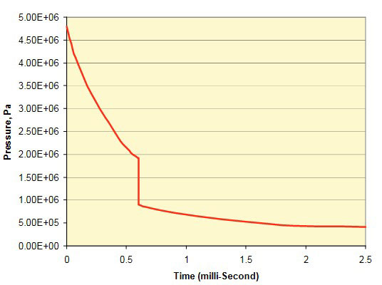
The pressure at a specific point in the fluid or on a structure steeply increases to the peak pressure followed by an exponential decay with time until the pressure has dropped to approximately 1/e of the peak pressure. After falling to approximately one-third of the peak pressure, the pressure level falls off inversely with distance.
The cavity of gaseous products left behind at high pressure forms a bubble which subsequently expands to relieve the difference in pressure, accelerating the surrounding fluid particles. The bubble continues to expand beyond the point of hydrostatic equilibrium (due to the inertia of the surrounding fluid) until a point of dynamic equilibrium is reached. The bubble then reverses its motion, continuing to contract until dynamic equilibrium is again reached, where it quickly rebounds and again begins to expand as illustrated in Fig. 3.
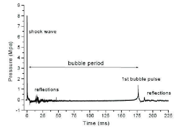
This oscillating bubble expansion and contraction continues until the energy of the reaction is fully dissipated or the bubble finally reaches the surface, venting the combustion products of the explosion. As the bubble rebounds, it greatly accelerates the surrounding water, generating a substantial pressure pulse (known as the bubble pulse). This bubble pulse can impart significant loads on structures in the vicinity.
The initial shock wave is followed by a further series of bubble oscillations (Figure 3) that gradually diminish in intensity until they are damped out by viscous fluid friction. Each of these bubble oscillations transmits a secondary pressure pulse through the surrounding water. Bubble pulsation generates considerably lower peak overpressures than the primary explosion shock wave, but the time scale of the oscillations is much longer as well, so that the overall positive impulse delivered to a target may be comparable or even greater than that from the primary shock wave; Figure 4.
In addition to the initial shock wave and bubble pulse, based on the location of the explosive charge with respect to the surface and sea floor, a surface vessel can also experience a combination of the following pressure waves as illustrated in Fig. 5.
- Free-surface reflection.
- Bottom reflection.
- Bottom refraction (not shown).
At the surface of a fluid, a reflected wave of negative pressure known as the “rarefaction wave” (a tensile or expanding wave) is formed with a value such that the sum of the direct and reflected pressures is zero along the boundary between air and water (Characteristics, Maintenance of Liquefied Petroleum Gas Vessels and Hull Integrity Management read in this article).

This rarefaction wave travels through the fluid region shortly after the incident shock wave at any point which causes the incident shock wave pressure profile to be truncated at a point in time called “surface cut-off.”; this is discussed later in Characteristics, Maintenance of Liquefied Petroleum Gas Vessels and Hull Integrity Management this article. Bottom reflected and refracted waves are dependent on the characteristics of the sea bottom and can contribute significant pressure waves in shallow water environments.
Cavitation
Cavitation is a phenomenon which occurs when a region of negative absolute pressure present in the water. The negative pressure causes the tensile force in the water, since the water cannot sustain this force, cavitation or separation is formed; see Figure 6.
Underwater Explosion Event
There are two types of cavitation’s present in the water “bulk cavitation” and “local cavitation”. Bulk cavitation can be considered as a large region of low pressure at the free surface while local cavitation is a small region of low pressure usually occurring at the fluid-structure interface. When cavitation occurs in water, it has a large effect on the overall response of the ship during an UNDEX event. Therefore, this phenomenon must be considered as a significant factor, and is included in the simulation process for a more accurate prediction.
Bulk cavitation
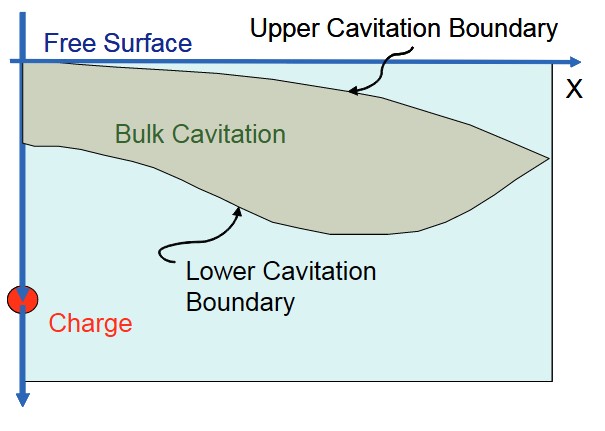
The incident shock wave is compressive in nature. A tensile or rarefaction wave is created when the shock wave is reflected from the free surface. Since water cannot sustain any significant tension, the fluid pressure is lowered and cavitation will occur when the pressure drops to zero or below. In reality, water can sustain a small amount of tension (approximately 0,2 bar of negative pressure), but zero bar is typically used for design and calculation purposes. Upon cavitation, the water pressure rises to the vapour pressure of water, approximately 0,02 bar. This cavitated region created by the rarefaction wave is known as the bulk cavitation zone. It has an upper and lower boundary and its extent is dependent on:
- the charge size,
- type,
- and depth.
The cavitation zone is symmetric about the vertical axis in the Figure 6. The velocities of water particles behind the shock wave front at the time of cavitation are dependent on their location relative to the charge and the free surface. Water particles near the free surface will have a primarily vertical velocity at cavitation. As the reflected wave passes, the particles will be acted upon by gravity and atmospheric pressure.
The upper cavitation boundary (Figure 7) is the set of points where the rarefaction waves passes and reduces the absolute pressure to zero or a negative value. The region will remain cavitated as long as the pressure remains below the vapour pressure. The total or absolute pressure which determines the upper boundary is a combination of:
- atmospheric pressure,
- hydrostatic pressure,
- incident shock wave pressure and rarefaction wave pressure.
- cavitation pressure, or zero pressure.
The lower cavitation boundary (Figure 7) is determined by equating the decay rate of the breaking pressure to the decay rate of the total absolute pressure. The breaking pressure is the rarefaction wave pressure that reduces a particular location of a fluid to the point of cavitation, i. e. zero pressure.
Local cavitation
The shock pressure pulses which are created by an underwater explosion impinging on a ship agitate the structure which causes dynamic responses. As long as the as pressure pulses impinge the flexible surface of the structure, a fluid-structure interaction takes place; Figure 8.
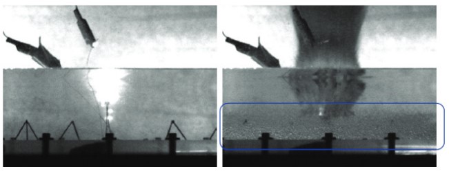
Right: Cavitation bubbles can be seen near the
bottom surface of the container
When this fluid-structure interaction occurs, the total pressure throughout the ship’s hull turns out to be negative. Since the water cannot sustain tension, the water pressure decreases the vapour pressure, and then local cavitation occurs.
Effect of UNDEX on surface ships
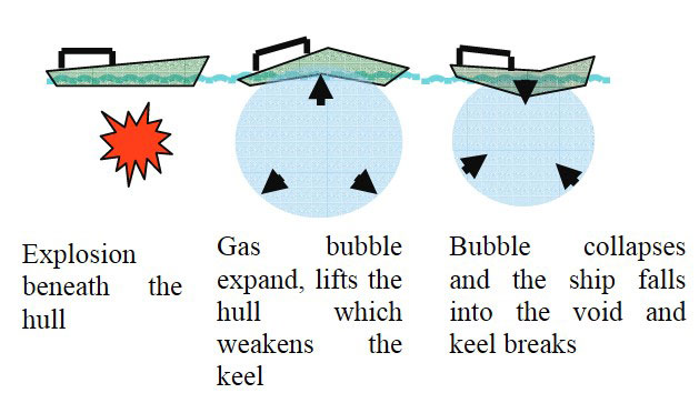
When an explosive charge is detonated at close range beneath a ship, the bubble initially lifts the ship upwards from the middle (Figure 9). This tends to weaken the ship’s keel. After the bubble has reached its maximum volume the surrounding water pressure will collapse it. The ship then falls into the void, still supported on its ends. The keel will then break under the ship’s own weight. The compression of the bubble will raise the temperature and the bubble will oscillate a few times. The ship may be destroyed during the subsequent oscillations if it manages to Ship Survivability and Cargo Tanks Placementsurvive the first, provided the charge is large enough.
If detonation occurs away from the ship, then gas bubble travels while expanding and may impact the ship several times as it collapses and expands again (Figure 10).
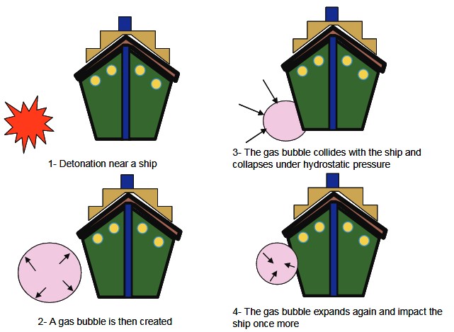
Figure 11 shows all sources of damage. Three typical scenarios and their possible effects are also noted on Figure 10.
In Scenario “A” of Figure 10 the shock wave embraces the whole ship rather than impacting on a local area. Major sources of damage are further discussed in the following sub-sections.
Shock damage
An explosive change detonated in close proximity of the hull (Scenario C Figure 11) could tear a hole depending on the size of the charge and the plate thickness. Another source of damage is projectile produced by the fragmentation of the charge casing. As the location of detonation moves away such that the chance of creating a hole in the hull diminishes, then the explosion envelops the complete ship. At large stand-off distances, the pressure loading on the ship hull rises instantaneously and decay exponentially. The hull responds by accelerating and it is possible for the hull to move faster than the water next to it. The inability of water to sustain tension causes a localised cavitation region to take place.
Later the cavitation region closes and the hull is loaded again. The incompressible water flow from the expanding bubble, can also contribute to the hull damage. The water flow ahead of bubble could impose a high load due to its momentum and last longer than the shock wave.
Bubble pulse and collapse
In a free-field underwater detonation, the gas bubble from the explosion remains confined by water on all sides. During the initial expansion of the gas bubble, the inertia of the out-flowing water causes the expansion to persist until gas pressure inside the bubble drops below the corresponding hydrostatic pressure for that depth. The bubble then collapses to a high internal pressure condition and expands again (see Figure 3).
Thus the initial shock wave is followed by a further series of bubble oscillations that gradually diminish in intensity until they are damped out by viscous fluid friction. Each of these bubble oscillations transmits a secondary pressure pulse through the surrounding water. Bubble pulsation generates considerably lower peak overpressures than the primary explosion shock wave, but the time scale of the oscillations is much longer as well, so that the overall positive impulse delivered to a target may be comparable or even greater than that from the primary shock wave. The pressure and positive impulse generated by bubble oscillations vary as functions of charge:
- weight,
- range,
- and depth.
Bursting of bubble could push a jet of water towards the vessel.
Surface cut-off damage
Since the air-water interface is not a rigid boundary, it reflects (Figure 12) as a tensile wave and imposes a tensile force on the water. As stated before, the water cannot support the tensile force and forms cavities which are filled with water vapour.
After the arrival of the rarefaction wave, the pressure drops to zero or negative value. This is called “cut-off” in the pressure. The pressure on the hull drops to zero. Another re-loading may occur (e. g. due to bubble pulse) when the hull is moving down towards the water surface. This is discussed further in Characteristics, Maintenance of Liquefied Petroleum Gas Vessels and Hull Integrity Managementthis article.
Bottom reflection
A bottom reflection wave (Figures 5 and 12) is also formed due to the reflection of the shock wave at the sea bottom. However, this type of wave is of less interest in an UNDEX event due to the dependence on the sea bottom characteristics and its closeness to the target.
Modelling of ship and fluid
Ship modelling
For reliable results the geometry needs to be modelled in detail that would lead to a large model requiring significant computing power. Some details of the model are shown in Figure 13. The structure is composed of a single material (steel) with isotropic elastic mechanical behaviour, and the section thicknesses may be position-dependent. The model can be created using ABAQUS/CAE or a similar modeller with an interface with ABAQUS. The lofting operation in ABAQUS/CAE can be used to merge the different cross-sections to form the exterior hull.
Fluid modelling
The infinite fluid can be modelled by fluid tetrahedral elements. The fact that the fluid is infinite is accommodated in the boundary conditions applied at the outer surface of the fluid which is modelled with infinite elements. The finite element model of the structure surrounded by the fluid can be seen in Figure 13.
The fluid elements are given the properties of water. The bulk modulus of water is specified using the formula:
ρC2
where:
- ρ – is the density of water;
- C – is the speed of sound in water.
An impedance-type radiation boundary condition is required at the outer surface of the fluid mesh to model the outward propagation of waves. The size of the fluid mesh depends on these conditions. The radiation boundary condition converges to the exact condition in the limit as they become infinitely distant from the structure. Such boundary conditions theoretically provide accurate results if the distance between the structure and the radiating surface is one half of the longest characteristic wave length. Based on the minimum distance published information an acceptable model should extend to about half of the ship length in each direction.
Modelling incident wave loading
As the wave progresses, the pressure in the incident wave at a point near the surface decrease and the head of the rarefaction wave moves down and away from the boundary and the source as discussed above. It is evident that the negative change in pressure at this point will encounter regions in which there is a smaller value of excess pressure. The net pressure behind the rarefaction will therefore become negative. If this regime persists the water will be required to develop a state of negative absolute pressure; Figure 14.
The oscillating bubble pulse can also introduce a low-frequency forcing function that can resonate a ship girder frequency. This is especially so when the period of the bubble pulse is in the vicinity of the natural frequencies of the ship girder. Fig. 15 illustrates a combination of the pressure waves.
The pressure time history of an explosion loading is required for different standoff distances (the distance between the structure and the explosive). The pressure time history at a particular standoff distance from the structure is given by the following equation for far filed explosions.
In the above equations:
- P(R, τ) – is the pressure time history,
- R – is the distance from the centre of the explosive,
- ac – is the radius of the spherical charge,
- f(τ) – is an exponential decay term,
- A, and B are the constants that are associated with the material of the charge.
Some recommended values obtained for these constants are shown in Table 1.
The above equations give a time history similar to what is shown in Figure 16:
The pressure load acting on the ship due to an underwater explosion changes with respect to both time and space. The pressure vs. time history of an explosive is the relation between pressure acting on the ship, as a spherical or plane wave, at the standoff point (the point where the wave hits the structure first), and time. If the UNDEX wave is considered as a spherical wave, the spatial distribution of a pressure wave on the structure can be considered as a spherical distribution. This spherical distribution is obtained using the “incident pressure wave equations”. The incident pressure equation can be written as a separable solution to the scalar wave equation of the form.
where:
- pI(t) – is specified through the pressure time history at the standoff point x0,
- px(xj) – is the spatial variation at a point.
where:
- xs – is the specified source point (point of explosion).
Considering the time delay required for the wave to travel from the standoff point to the point xj, yields:
In Equation 7, c0 is the wave speed in the fluid, and τj is the “retarded time” because it includes a shift corresponding to the time required for the wave to travel from the standoff point to xj.
The fluid and ship interaction
Calculating the response of a surface vessel to an underwater explosion involves integration of the structural behaviour and its effects on the surrounding fluid and vice-versa. When the vessel is exposed to a shock wave produced by an explosion, the structure deforms and displaces fluid surrounding it. The pressure distribution surrounding the structure is also affected by the motion of the ship due to the shock wave.
This interaction between the fluid and the structure must be modelled using coupled fluid-structure equations for a duration which is required for the ship vibration to subside. A surface-based procedure can be used to enforce a coupling between the structural surface nodes and the fluid surface nodes. The interaction is defined between the fluid and the structure surface meshes.
The reflections of the pressure wave after striking the structure are called scattered waves, which must be taken into account. Therefore, the applied load consists of the sum of known incident and unknown scattered pressure wave components. The incident wave field is the pressure time history obtained from the similitude relations and the incident pressure wave equations (see Characteristics, Maintenance of Liquefied Petroleum Gas Vessels and Hull Integrity Management in this article).
The equations of motion used in this analysis are of the form:
where:
- Ms – is the structural mass,
- Cs – is the structural damping matrix,
- Ks – is the structural stiffness matrix,
- pI – is the incident shock pressure wave,
- ps – is the scattered pressure wave.
In the above equations, u is the structural displacements, Mf is the mass of fluid, Cf is the fluid damping matrix, Kf is the fluid stiffness matrix, and the transformation matrix Sfs integrates the fluid and structural degrees of freedoms and was defined on all of the interacting fluid and structural surfaces. The fluid traction T in Equation (11) is the quantity that describes the mechanism by which the fluid drives the solid. By substituting equation (12) in Equations (10) and (11), we obtain the fluid equation in terms of the unknown scattered pressure term. The resulting equation is solved together with Equation (10) to obtain the response of the ship structure.
Surface based interaction
The fluid-structure interaction capabilities of ABAQUS, such as solving for the scattered term obtained due to reflection of the pressure wave and inclusion of the coupling term in the structural and fluid governing differential equations can be used for this purpose. In this type of coupled fluid-solid analysis, the fluid fields are strongly dependent on conditions at the boundary of the fluid medium. The fluid medium consists of different sub-regions where different conditions must be specified, such as the radiation boundary condition to model infinite fluid medium and fluid-structure interaction conditions.
The fluid-structure interface is the region where the fluid medium is directly coupled to the motion of the solid. The procedure uses a surface-based fluid-structure medium interaction procedure. The coupling is obtained by designating the fluid and the structural surface nodes at the interface as the master and the slave nodes, respectively. The slave side receives point tractions based on interpolation with the shape functions from the master side. If the solid medium is designated as slave, the values on this surface are constrained to equal values interpolated from the master surface; Figure 17.
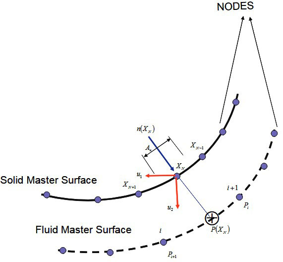
The projections of slave nodes onto the master surface are found, and the areas and the normal associated with the slave nodes are computed. The projections of these points, p(XN), are used to identify the master nodes in the vicinity of this projection. Variables at the slave nodes, XN, are then interpolated from the variables at the identified master surface nodes near the projection.
The point-wise fluid-solid coupling condition is enforced at the slave nodes, resulting in fluid pressure degrees of freedom added to the structural slave surface. The contribution of a single slave node XN to the coupling term in the acoustic equation is approximated by the following equation:
where:
- – is structural acceleration at the slave node,
- AN – and are areas and normal associated with the slave nodes,
- Hi(p(XN)) – are the interpolants on the fluid master surface evaluated at projections p(XN).
The summation is for all master nodes “i”, in the vicinity of the slave node projection. The entire coupling matrix is computed by repeating this step for all the slave nodes. The contribution to the coupling term in the structural equation is approximated by:
Conclusions
Numerical methods for the analysis of fluid-solid interaction under severe underwater shocks implemented in commercial software packages are now accurate enough as well as practical enough to provide an alternative to physical testing. Moreover such methodology can be used to obtain the lightest and safest structures which satisfy the safety of crew, port and the asset. It is suggested that in order to avoid complex and expensive physical testing numerical techniques to be considered for UNDEX. Currently commercial vessels are seldom studied for fortification against underwater explosion. The methodology integrates the fluid and structural behaviour as a transient dynamic fluid-structure interaction problem.
A detailed qualitative description of UNDEX loading on surface structures is given in the paper. A methodology is then described that accounts for explosions due to a fixed amount of charge in the vicinity of the structure. This technique also can be used for obtaining an optimal design.
The current UNDEX response capability can be utilized in design of a safer next generation of hydrocarbon carrying vessels as well as enhancing UNDEX capacity of existing fleets.
Another major problem which is not addressed in the paper is the effect of strong vibration on the Safety Precautions and Measures on Gas tankerssafety critical system.
Acknowledgements
This article builds upon the work of many authors. Since the availability of references is the aim of the article, it is not always possible to give credit to the original authors. The author would like to acknowledge Dr. Bijan Djahansouzi and Miss. Yasmin Yasseri for their helpful comments. The views of the author do not purport to reflect the position of his employer or the reviewers.