Cargo Equipment plays a vital role in the efficient handling of diverse materials. This category includes essential systems like pumps, compressors and heating units. Pumps are fundamental for transferring liquids, crucial for loading, unloading and internal movements. Compressors are critical for managing gaseous cargoes and powering pneumatic tools in cargo operations. These components of Cargo Equipment are indispensable for the smooth flow of goods.
- Cargo Pumps
- Typical Pimp Installation
- Main Cargo Pumps
- Stripping/Spray Pump
- Emergency Cargo Pump
- Critical Items of Cargo Pumps
- Cargo Compressors
- Heavy Duty Compressors
- Low Duty Compressors
- Seal-Gas
- Surge Control System
- Inlet Guide Vanes
- Boil-off/Warm-up Heaters
- Feature
- Typical Heaters
- Vaporizers
- Features
- LNG Vaporizer
- Forcing Vaporizer
- Mist Separator
Beyond movement, Cargo Equipment is also key to maintaining cargo quality. Heating systems, a crucial part of Cargo Equipment, ensure temperature-sensitive goods are transported safely and without degradation. Reliable Cargo Equipment, including pumps, compressors and heating systems, is therefore paramount for secure and efficient cargo handling in various industries.
Cargo Pumps
Typical Pimp Installation
In general all LNGC’s, regardless of containment system, (membrane or Moss-Rosenberg) are fitted with submerged, electric, centrifugal Use of Cargo Pumps on Liquefied Gas Carrierscargo pumps. They are installed at the bottom of each tank.
Two sizes of pump are typically used: main cargo and stripping/spray pumps are installed as fixed units (i. e. two main cargo pumps and one stripping/spray pump per tank).
Additionally, provision is made at each tank to introduce an emergency cargo pump in case the failure of the two cargo pumps mounted in tank. One emergency pump is carried on each ship.
The cargo pumps are started and stopped from the CACC (Centralized Administration and Control Center) by IAS (Integrated Automation System) mimics. The control is obtained through the different mimics where the cargo pumps are present. They will also be automatically stopped in the event of various shutdown trips being activated both in relation to the cargo system and the pumps themselves.
Each cargo pump electric motor is protected from:
- thermal overload (overcurrent);
- under-current (no load operation);
- imbalance between phases (single-phasing);
- start time limits.
Under normal circumstances, the cargo pumps are started directly on-line. Under emergency conditions there is a facility to connect either of the cargo pumps to the emergency switchboard through the soft starting control, which is located between the cargo switchboard rooms on upper deck. Only one pump at a time can be connected in this manner, via portable flexible cables.
The power supply to the cargo pump motors is made available via cargo switchboards, which are arranged in two independent sections that are normally operated as coupled by a bus-tie connection or independently. No.1 cargo switchboard supplies the starboard pumps in all four tanks, while No.2 cargo switchboard supplies the port cargo pumps.
Each cargo switchboard can be supplied by either or both the main switchboards.
Due to high electrical load imposed on the cargo switchboards by the running of main cargo pumps, there may be a limitation, (particularly on older vessels) on the number of pumps that can be run simultaneously, depending on the electrical power availability.
Main Cargo Pumps
The following characteristics of typical main cargo pump for a LNG carrier of 138 000 m3 capacity may be considered indicative for ships with capacity ranging between 135 000 and 150 000 m3 (Table 1).
| Table 1. The Following Characteristics of Typical Main Cargo Pump for a LNG Carrier | |
|---|---|
| CHARACTERISTIC | 135 000-150 000 m3 LNGC |
| No. of stages | 1 |
| Operating temperature | -163 °C |
| Capacity rated flow | 1 700 m3/h |
| Rated head | 155 m |
| Power rated | 465 kW |
| Efficiency | 77,1 % |
| Rotational speed | 1 780 rpm |
Figure 1 shows a sketch of the above cargo pump as well as diagrams illustrating its characteristics.

This pump is rated to discharge 1 700 m3/h at 155 meters head of LNG. For optimum discharge results, bulk discharge will be carried out with 8 pumps running in parallel.
The pump discharge valves will be throttled to ensure optimum performance as indicated by the pump performance graph.
During the course of discharge, changes in flow rate and tank levels will alter these readings and the discharge valve will have to be re-adjusted accordingly. Under normal conditions it should be possible to maintain full discharge rate until the tank level approaches approximately 0,7 meters at which time the pump will start to cavitate and lose suction as indicated by fluctuations in the discharge pressure and ammeter readings.
The discharge valves should be throttled to stabilize conditions and one pump stopped if necessary. The remaining pump is progressively throttled in to maintain suction and to prevent operation of the low discharge pressure trip, until a level of 0,3 m is reached.
This level when the pump loose suction at even keel and is identified as “heel“.
By trimming the vessel 1 m or more by the stern, it should be possible to substantially reduce the amount of liquid remaining in the tanks before the pumps are stopped.
The cargo pumps may be run in closed circuit on their own tanks by opening the loading valve. This may be required if the discharge is temporarily halted when the tanks are at low level, thereby avoiding the problem of restarting with low level and low discharge pressure.
The cargo pumps will be automatically stopped should any of the following occur:
- cargo tank pressure below or equal to secondary barrier pressure plus 0,5 kPa (ESDS1);
- vapor header pressure below or equal to atmospheric pressure plus 0,3 kPa;
- extreme high level in cargo tank (99 % volume);
- activation of emergency shut down trip (ESDS);
- activation of ship/shore pneumatic, fiber-optic or electrical shutdown (ESDS);
- motor single-phasing;
- low motor current;
- high motor current (electrical overload);
- low discharge pressure with time delay at starting;
- CACC emergency stop.
Stripping/Spray Pump
The following characteristics of a typical stripping/spray cargo pump for a LNG carrier of 138 000 m3 capacity may be considered indicative for ships with capacity ranging between 135 000 and 150 000 m3 (Table 2).
| Table 2. The Following Characteristics of Typical Stripping/Spray Cargo Pump for a LNG Carrier | |
|---|---|
| CHARACTERISTIC | 135 000-150 000 m3 LNGC |
| No. of stages | 2 |
| Operating temperature | -163 °C |
| Capacity rated flow | 50 m3/h |
| Rated head | 145 m |
| Power rated | 18 kW |
| Efficiency | 54,7 % |
| Rotational speed | 3 560 rpm |
Figure 2, shows a sketch of the above pump as well as diagrams of its characteristics. A stripping/spray pump is installed in each tank for spray cooling purposes and for forced vaporization of LNG.
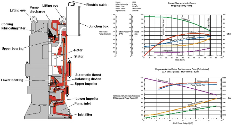
The pumps are started and stopped from the CACC. In an emergency, all pumps will be stopped by activation of an ESDS trip.
These pumps can be used:
- to cool down the main liquid lines prior to discharging;
- to cool the tank membranes and insulation during ballast voyage prior to arrival at loading terminal by discharging LNG to the spray header in the tanks;
- to pump LNG from the tanks to the forcing vaporizer when forced vaporization of LNG in the boilers is required;
- to enable each cargo tank to be stripped as dry as possible for reasons such as, commercial interests, and necessity to enter the tank.
Whenever possible, the stripping/spray pump should be started early enough to avoid possible starting problems due to very low tank levels (about 0,5 m minimum). The spray pumps should not be started at a level below 0,25 m, with a level of 0,15 m at even keel when pump can loose suction.
The stripping/spray pumps will be stopped automatically should any of the following occur:
- cargo tank pressure below or equal to IBS space pressure plus 0,5 kPa (ESDS ESDS signifies that all cargo plant is shut down in addition to the pump(s) on the tank(s) in questionx);
- vapor header pressure below or equal to atmospheric pressure plus 0,3 kPa (ESDS);
- extreme high level in cargo tank (99 % volume);
- activation of ESDS trip (ESDS);
- activation of ship/shore pneumatic, fiber-optic or electrical shutdown (ESDS);
- motor single-phasing;
- low motor current;
- high motor current (electrical overload);
- low discharge pressure with time delay at starting;
- CACC emergency stop.
Emergency Cargo Pump
The following characteristics of a typical emergency cargo pump for a LNG carrier of 138 000 m3 capacity may be considered indicative for ships with capacity ranging between 135 000 and 150 000 m3 (Table 3).
| Table 3. The Following Characteristics of a Typical Emergency Cargo Pump for a LNG Carrier | |
|---|---|
| CHARACTERISTIC | 135 000-150 000 m3 LNGC |
| No. of stages | 1 |
| Operating temperature | -163 °C |
| Capacity rated flow | 550 m3/h |
| Rated head | 155 m |
| Power rated | 171 kW |
| Efficiency | 67,8 % |
| Rotational speed | 3 560 rpm |
Each Independent Cargo Tankscargo tank is equipped with an emergency pump well. See Figure 3.
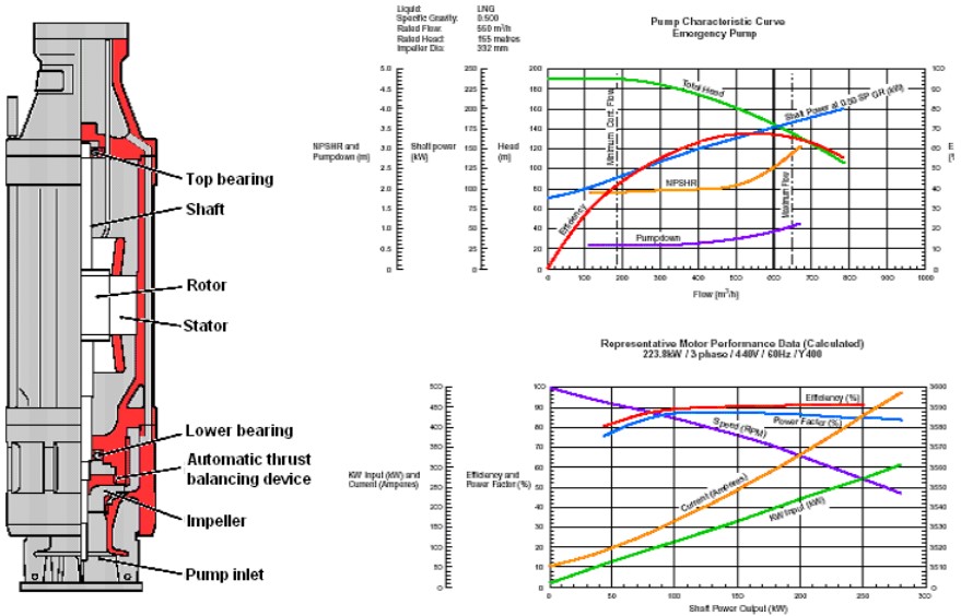
This pump well has a foot valve, which is held in the closed position by highly loaded springs.
Should a failure of either one or both main cargo pumps in one tank require the use of the emergency pump, it is lowered into the emergency pump well after the well has been purged with nitrogen with a small flow of nitrogen maintained while the pump is being installed. The weight of the emergency pump overcomes the compression of the springs to open the foot valve.
Electrical connections are made to the fixed junction box, which is located adjacent to each pump well.
All safety devices are transferred to the emergency pump when the circuit breaker is engaged, as they are the same for the main cargo pumps. The same starting procedures and schematic mimics are used as that for the main cargo pumps.
Critical Items of Cargo Pumps
Several critical items of cargo pumps are as follows:
- Clearance at the bottom between the bell mouth to the pump suction and the tank bottom is to be such to accommodate all service conditions.
- Excessive vibration may cause damage and excessive strain to the tower guide pin.
- In order to avoid cavitation, a non-return spring valve is generally installed at the discharge of the pump.
- Excessive sealing wear may be caused by the debris at the bottom of the tank due to ineffective strainers in the line.
Excessive bearing wear may be caused by vibration due to misalignment and unbalance of rotating components.
Cargo Compressors
Two heavy duty (HD) compressors, installed in the cargo machinery room on deck, are provided for handling gaseous fluids; LNG vapor and various mixtures of LNG vapor, inert gas or air during the cooling down, cargo operation and conditioning of tanks.
Two low duty (LD) compressors, installed in the cargo machinery room on deck, are provided for handling the LNG vapor (BOG) for the boiler fuel produced by the natural boil off and forced vaporization, which is used as fuel.
The HD and LD compressors are driven by electric motors, installed in an electric motor room segregated from the compressor room by a gas tight bulkhead. The shaft penetrates the bulkhead with a gas tight shaft seal.
Heavy Duty Compressors
The following characteristics of a typical heavy-duty compressor for a LNG carrier of 138 000 m3 capacity may be considered indicative for ships with capacity ranging between 135 000 and 150 000 m3 (Table 4).
| Table 4. The Following Characteristics of a Typical Heavy-Duty Compressor for a LNG Carrier | |
|---|---|
| CHARACTERISTIC | 135 000-150 000 m3 LNGC |
| Type | Centrifugal, single stage, fixed speed with adjustable guide vanes |
| Volume flow | 32 000 m3/h |
| Inlet pressure | 103,0 kPa |
| Outlet pressure | 200,0 kPa |
| Inlet temperature | -140 °C |
| Discharge temperature | -109 °C |
| Shaft speed | 11 531 rpm |
| Motor speed | 3 560 rpm |
| Rated motor power | 950 kW |
The compressors are operated locally or from the CACC.
The following conditions trip the compressors:
- activation of ESDS;
- differential pressure: vapor header/atmospheric pressure = 0,3 kPa;
- differential pressure: vapor header/IBS pressure header = 0 kPa;
- tank No.1, 2, 3 or 4 – very high liquid level;
- local control system action:
- oil temperature;
- oil pressure;
- discharge gas temperature;
- seal gas pressure.
- electric power failure;
- ventilation flow failure in the electric motor room.
Low Duty Compressors
The following characteristics of a typical low duty compressor for a LNG carrier of 138 000 m3 capacity may be considered indicative for ships with capacity ranging between 135 000 and 150 000 m3 (Table 5).
| Table 5. The Following Characteristics of a Typical Low Duty Compressor for a LNG Carrier | |
|---|---|
| CHARACTERISTIC | 135 000-150 000 m3 LNGC |
| Type | Centrifugal, single stage, variable speed with adjustable guide vanes |
| Volume flow | 8 500 m3/h |
| Inlet pressure | 103,0 kPa |
| Outlet pressure | 200,0 kPa |
| Minimum inlet temperature | -140 °C |
| Shaft speed | 13 997 ~ 27 994 rpm |
| Motor speed | 1 780 ~ 3 560 rpm |
| Rated motor power | 430 kW |
The compressors are operated locally or from the CACC.
The following conditions trip the compressors:
- activation of ESDS;
- differential pressure: vapor header/atmospheric pressure = 0,3 kPa;
- differential pressure: vapor header/IBS pressure header = 0 kPa;
- very high liquid level in tanks;
- local control system action:
- oil temperature;
- oil pressure;
- discharge gas temperature;
- seal gas pressure.
- electric power failure;
- ventilation flow failure in the electric motor room.
Seal-Gas
Each compressor shaft is equipped with a forced nitrogen bulkhead shaft seal, preventing any combustible gas from entering the electric motor room. Seals are fixed to the bulkhead and float on the shafts, supported by ball bearings.
A seal gas system is provided to seal the compressor shaft opening from the release of explosive LNG vapor. The seal consists of two chambers. The first chamber on the impeller side allows any leak off gas to be drawn back to the suction side of the compressor, while the second chamber is fed with dry nitrogen produced by the nitrogen generators on board.
The system is maintained by a pressure control valve, where seal gas pressure is always higher than the suction pressure (usually adjusted at 30 kPa). To avoid LNG vapor leaking to the atmosphere during standstill, a vent line valve is fitted, which leads to No.4 vent mast. This vent line valve must be closed prior to starting the compressor.
Seals are particularly sensitive to damage due to vibrations and all efforts should be made to minimize the vibrations.
Surge Control System
An automatic surge control system is provided to ensure that the compressor flow rate does not fall below the designed minimum. Below this rate, the gas flow will not be stable and the compressor will be liable to surge, causing shaft vibration, which may result in damage to the compressor.
All the gas compressors are equipped with an automatic surge control system, which consists of:
- a flow transmitter;
- a compressor differential pressure transmitter;
- a ratio station;
- an anti-surge controller;
- a bypass valve on the gas stream.
On the basis of a preset ratio between the gas flow and compressor differential pressure signals, the anti-surge controller produces a signal, which modulates the compressor bypass valve.
Inlet Guide Vanes
To achieve the required gas flow, the compressors have inlet guide vanes fitted at the suction end.
The vanes are operated by pneumatic actuators, which receive control signals from the flow controller. Rotation of the vanes is possible through an angle of 100°. The position is indicated both locally and at the CACC.
Boil-off/Warm-up Heaters
Feature
Typically, there are two steam heated boil-off/warm-up heaters located in the cargo machinery room situated on the main deck.
Heaters, which are of the shell and tube type, are used for the following functions:
- heating the LNG vapor, which is delivered by either of the heavy duty compressor compressors at the specified temperature for warming up of cargo tanks before gas freeing;
- heating product from the forcing vaporizer in conjunction with the heavy-duty compressors, for the operation of purging cargo tanks with LNG prior to cool down;
- heating boil-off gas supplied to the main boilers via the low duty compressors (or free flow).
Typical Heaters
The characteristics of a typical heater for a Key Systems for LNG Carriers Containment and Safety: Design and OperationLNG carrier of 138 000 m3 capacity are given in the following table. These characteristics may be considered indicative for ships with capacity ranging between 135 000 and 150 000 m3 (Table 6).
| Table 6. The Following Characteristics of a Typical Heater for a LNG Carrier | |
|---|---|
| CHARACTERISTIC | 135 000-150 000 m3 LNGC |
| Type | Horizontal shell and U-tube heat exchanger |
| Rated capacity | 16 000 ~ 24 500 kg/h |
| Heating medium (steam) | 1 750 ~ 3 030 kg/h |
| Vapor outlet temperature | +15 °C ~ +80 °C |
Vaporizers
Features
The LNG vaporizer and the forcing vaporizer, are located in the cargo machinery room forward HD and LD compressors.
LNG Vaporizer
The characteristics of a typical LNG vaporizer for a LNG carrier of 138 000 m3 capacity are given in the following table. These characteristics may be considered indicative for ships with capacity ranging between 135 000 and 150 000 m3 (Table 7).
| Table 7. The Following Characteristics of a Typical LNG Vaporixer for a LNG Carrier | |
|---|---|
| CHARACTERISTIC | 135 000-150 000 m3 LNGC |
| Type | Horizontal shell and “U” tube design |
| Heating medium (steam) | 4 160 ~ 5 810 kg/h |
| Inlet temp of the medium | 170 °C |
| Maximum gas flow | 21 300 kg/h |
| Inlet LNG temperature | -163 °C |
| Outlet gas temp | -140 to 20 °C |
Alarms are provided on the outlet gas temperature, high level and low temperature of the condensate water.
The LNG vaporizer is used for the following operations:
a) Discharging cargo at the design rate without the availability of a vapor return from the shore.
If the shore is unable to supply vapor return, LNG is fed to the vaporizer by using one stripping pump or by bleeding from the main liquid line. The vapor produced leaves the vaporizer at approximately -140 °C and is then supplied to cargo tanks through the main vapor header. Vapor pressure in the cargo tanks will normally be maintained at 110 kPa (minimum 104 kPa) during the whole discharge operation. Additional vapor may be generated by the tank sprayer rings, with the LNG being supplied by the stripping/spray pump.
If the back-pressure in the discharge piping to shore is not sufficient to have a minimum of 300 kPa at the inlet to the vaporizer, a stripping/spray pump will be used to supply liquid to the vaporizer.
b) Purging of cargo tanks with NG after inerting and prior to cooldown. LNG is supplied from the shore to the vaporizer via the stripping/spray line. The vapor produced at the required temperature +20 °C is then passed to the cargo tanks This operation is the normal procedure if the cargo tanks have been inerted with inert gas containing carbon dioxide x.
.
Forcing Vaporizer
The characteristics of a typical LNG vaporizer for a LNG carrier of 138 000 m3 capacity are given in the following table. These characteristics may be considered indicative for ships with capacity ranging between 135 000 and 150 000 m3 (Table 8).
| Table 8. The Following Characteristics of a Typical LNG Vaporixer for a LNG Carrier | |
|---|---|
| CHARACTERISTIC | 135 000-150 000 m3 LNGC |
| Type | Horizontal shell and “U” tube design |
| Heating medium (steam) | 2 660 kg/h |
| Inlet temp of the medium | 170 °C |
| Maximum gas flow | 7 000 kg/h |
| Inlet LNG temperature | -163 °C |
| Outlet gas temperature | -40 °C |
The forcing vaporizer is used to supplement boil-off gas for fuel gas burning up to 100 %. (plus 5 % of margin). LNG is supplied by a stripping/spray pump and flow is controlled by an automatic inlet feed valve, which receives its signal from the boilers combustion control system.
Alarms are provided on the outlet gas temperature, high level and low temperature of the condensate water.
The forcing vaporizer is equipped with a temperature control system to obtain a constant and stable discharge temperature for various ranges of operation. The temperature of the gas produced is adjusted by injecting a certain amount of bypassed liquid into the outlet side of the vaporizer through a temperature control valve and liquid injection nozzles.
Both the LNG and forcing vaporizer tube stacks are fitted with spiral wire inducers to promote turbulence, thereby ensuring efficient heat transfer and production of superheated LNG vapor at the exit of the tube nests.
A re-evaporator is also used to ensure that accumulation of non-vaporized liquid at the vaporizer discharge is avoided and that the output is at a stable temperature.
This is made possible by:
- Two knitted mesh filters inserted in the gas flow path to fractionate the droplets and create the necessary turbulence to transform the small droplets injected into a fine fog of liquid gas and also to moisten the mesh wires acting as vaporizing surface.
- Two conical baffles installed in the tube to allow eventually accumulated liquid to be directed into the gas stream on the pipe bottom.
Mist Separator
A mist separator is fitted downstream of the forcing vaporizer to serve as a moisture separator and prevent any carry over of liquid to the low duty compressors.
The followings are the characteristics of a typical mist separator for a LNG carrier of 138 000 m3 capacity are given in the following table. These characteristics may be considered indicative for ships with capacity ranging between 135 000 and 150 000 m3 (Table 9).
| Table 9. The Following Characteristics of a Typical Mist Separator for a LNG Carrier | |
|---|---|
| CHARACTERISTIC | 135 000-150 000 m3 LNGC |
| Type | Shell with in/out nozzles and drain |
| Glas flow | 7 800 kg/h |
| Service temperature | -40 °C |
An alarm is provided to monitor the level of chained/captured LNG in the mist separator.

- The Society of International Gas Tanker and Terminal Operators (SIGTTO). Liquefied Gas Handling Principles on Ships and in Terminals (LGHP4) / 4th Edition: 2021.
- The international group of liquefied natural gas importers (GIIGNL). LNG custody transfer handbook / 6th Edition: 2020-2021.
- American Gas Association, Gas Supply Review, 5 (February 1977).
- ©Witherby Publishing Group Ltd. LNG Shipping Knowledge / 3rd Edition: 2008-2020.
- CBS Publishers & Distributors Pvt Ltd. Design of LPG and LNG Jetties with Navigation and Risk Analysis / 4th Edition.
- NATURAL GAS PROCESSING & ITS ENERGY TRANSITION ROLE: LNG, CNG, LPG & NGL Paperback – Large Print, November 14, 2023.
- American Gas Association, Gas Supply Review, 5 (February 1977).
- The Society of International Gas Tanker and Terminal Operators (SIGTTO). Ship/Shore Interface / 1st Edition, 2018.
- Department of Transportation, US Coast Guard, Liquefied Natural Gas, Views and Practices Policy and Safety, p. IV-3.
- Department of Transportation, US Coast Guard, Liquefied Natural Gas, Views and Practices Policy and Safety, p. IV-4.
- Federal Power commission, Trunkline LNG Company et al., Opinion No. 796-A, Docket No s. CP74-138-140 (Washington, D. C.: Federal Power Commission, June 30, 1977).
- Federal Power Commission, Final Environmental Impact Statement Calcasieu LNG Project Trunkline LNG Company Docket No. CP74-138 et al., (Washington, D. C.: Federal Power Commission, September 1976).
- Federal Power Commission, «FPC Judge Approves Importation of Indonesia LNG».
- OCIMF, ICS, SIGTTO & CDI. Ship to Ship Transfer Guide for Petroleum, Chemicals and Liquefied Gases / 1st Edition, 2013.
- Federal Power Commission, «Table of LNG imports and exports for 1976», News Release, June 3, 1977, and Federal Energy Administration, Monthly Energy Review, March 1977.
- Office of Technology Assessment LNG panel meeting, Washington, D. C., June 23, 1977.
- Socio-Economic Systems, Inc., Environmental Impact Report for the Proposed Oxnard LNG Facilities, Safety, Appendix B (Los Angeles, Ca.: Socio-Economic Systems, 1976).
- «LNG Scorecard», Pipeline and Gas Journal 203 (June 1976): 20.
- Dean Hale, «Cold Winter Spurs LNG Activity»: 30.