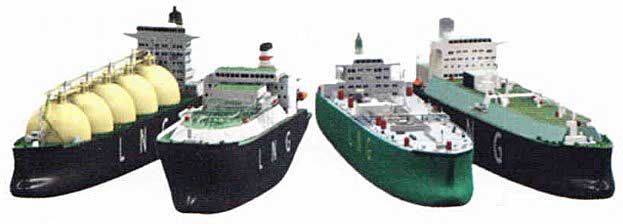
The fleet of liquefied gas ships currently in service numbers approximately 1, 100, of which about 800 are LPG carriers, over 200 LNG carriers and approximately 90 are ethylene carriers. This article describes difference in types, layouts and designs of Liquefied Gas Carrier.
- Profile of the World Gas Fleet
- Gas Carrier Types
- Fully Pressurised Ships
- Semi-Pressurised/Semi-Refrigerated or Semi-Pressurised/Fully-Refrigerated
- Fully-Refrigerated
- Ethylene Carriers
- LNG Carriers
- General Gas Carrier Layout
- General Layout of the Deck Piping on a Fully Refrigerated LPG/Carrier
- Categorisation of Gas Ship Types
- Surveys and Certification
Profile of the World Gas Fleet
Gas carriers are divided into two main groups:
- Liquefied Petroleum Gas (LPG) Carriers, which are designed to carry mainly butane, propane, butadiene, propylene, Vinyl Chloride Monomer (VCM) and are also able to carry anhydrous ammonia.
- Liquefied Natural Gas (LNG) Carriers, which are designed to carry liquefied natural gas (which is mostly methane).
Gas carriers arc classed in three types based on hazard potential:
- A type 1G ship is a gas carrier intended to transport products that require maximum preventive measures to prevent the escape of such cargo (chlorine, ethylene oxide, methyl bromide, sulphur dioxide).
- A type 2G ship is a gas carrier intended to transport products that require significant preventive measures to prevent the escape of such cargo (ethane, methane (LNG)), ethylene.
- A type 2PG ship is a gas carrier of less than 150 m in length, intended to transport products that require significant preventive measures to prevent the escape of such cargo and where cargoes are carried in independent type “C” tanks designed for a MARVS (Maximum Allowable Relief Valve Setting) of at least 0,7 bar gauge and a cargo containment system design temperature of -55 °C or above (i. e. ammonia, butadiene, butane, propane etc).
All ships of this description over 150 m can be considered a type 2G ship. - A type 3G ship is a gas carrier intended to carry products that require moderate preventive measures to preclude the escape of cargo (nitrogen, refrigerant gases (CFC)).
To remember what a type “2PG” gas carrier is think of the P = Pressurised.
Gas Carrier Types
All gas cargoes are transported in liquid form (i. e. they are not carried as a gas in its vapour form) and, because of their physical and chemical properties, they are carried under one of the following conditions:
- A pressures greater than atmospheric.
- At temperatures below ambient.
- A combination of both.
Because of this, gas carriers are generally grouped as follows:
- Fully pressurised.
- Semi-pressurised and refrigerated.
- Fully refrigerated.
Note: these grouping names are more frequently used when discussing the classes and types of LPG carriers rather than LNG carriers.
Recap on Tank Types used: Type “A”: Constructed of plane surfaces (prismatic tanks); Type “B”: Spheres; Type “C”: Cylindrical pressure vessels.
Fully Pressurised Ships
This ship type was the first to carry liquefied gases and they have a cargo capacity of up to about 3 500 m3.
The cargo is carried in spherical or cylindrical steel tanks, designed for a working pressure of 17,5 kg/cm2. This corresponds to the vapour pressure of propane at 45 °C, which is the maximum ambient temperature at which the ship is likely to operate.
No temperature or pressure control mechanisms are necessary.
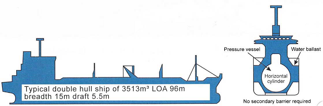
The tanks are generally Type “C” spheres and so no secondary barrier is required. A double bottom is constructed for the ballast water and the hold space around the cargo tanks does not need to be inerted, although the US Coastguard will require that they are for vessel enry to the USA, and require that no tank pressure exceeds 4,5 barg.
Advantages
- They are built with ordinary grades of steel as the cargo is carried al ambient temperature with no insulation required.
- No reliquefaction plant is needed.
- Operations are simpler.
Disadvantages
- Because of their shape, the use of underdeck space cannot be optimised.
- High design pressure requires considerable tank wall thickness, with a consequent increase in displacement weight and cost.
- The weight in tonnes of cargo carried is lower than for a refrigerated ship of similar size because of the cargo density differential.
- As the diameter of the tanks increases, the wall thickness increases to withstand the same pressure. The decreasing ratio of cargo carried to weight of tank makes this solution uneconomical over long haul routes.
Remember The Gases and Their Properties, Liquefaction Process (LNG/LPG)Boyles Law.
Fully Pressurised LPG Carrier
Fitted with Type “C” Tank – The LPG/C “Lady Hilde”


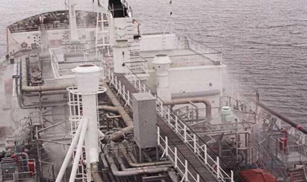
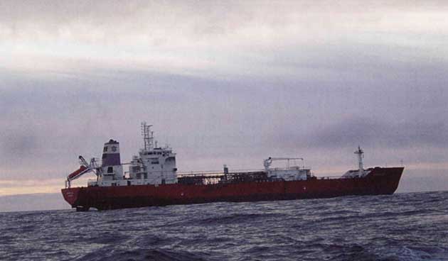
Semi-Pressurised/Semi-Refrigerated or Semi-Pressurised/Fully-Refrigerated
The vessels are fitted with a refrigeration plant that provides a fully-refrigerated ability while still having a high design pressure for the cargo tanks (pressure vessels), albeit below that required for fully-pressurised carriage. The tanks are cylindrical in shape and of a thinner construction than the fully- pressurised ships.
Semi-pressurised/semi-refrigerated ships, which are now quite rare, ranged up to 5 000 m3 in size. Their construction was based on carrying propane at a pressure of 8,5 kg/cm2, and a temperature of -10 °C.
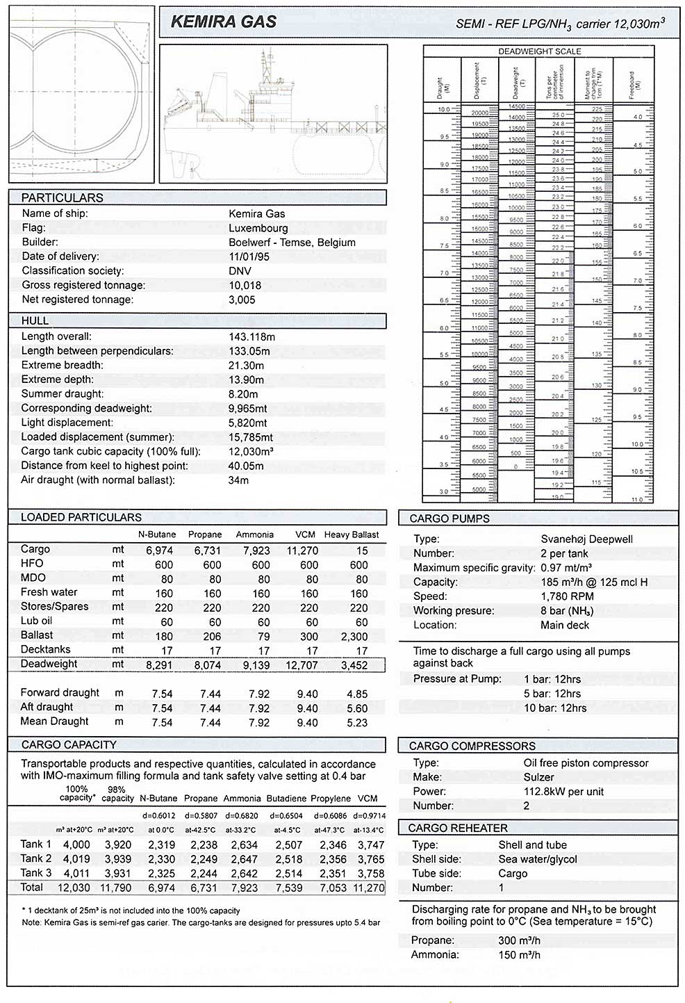
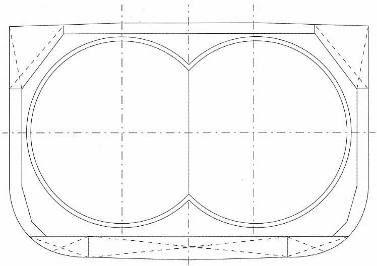
Semi-pressurised/fully-refrigerated ships generally range up to 15 000 m3. They can be designed to carry the cargoes in cylindrical or spherical tanks and are designed for a minimum service temperature of -48 °C and a working pressure of approx. 5 to 8 kg/cm2.
Read also: The Gases and Their Properties, Liquefaction Process (LNG/LPG)
The reliquefaction plant will usually have a substantial capacity and can, if required, load the cargo as a gas and then reliquefy it on board. The ships can heat or cool cargo during loading operations, or while at sea, and are also able to raise the temperature of the cargo when discharging.
Where a reliquefaction plant is fitted it will allow for a reduction in the thickness of the walls of tanks.
Note: The thicker the insulation surrounding the tank the less work the reliquefaction plant is required to do.
The inner hull volume is used more efficiently than on the fully pressurised vessels and the number of tanks varies from 2-6.
A double bottom is constructed for ballast water and the hold space around the cargo tanks does not need to be inerted, although, as in the case of the fully pressurised vessel, the USCG will require this and prohibit tank pressures from exceeding 4,5 barg (as a precaution against BLEVE).
Advantages
The advantages of this type over fully-pressurised ships are:
- More cargo can be carried in a tank of the same capacity.
- A tank of the same capacity is lighter and cheaper to build.
- Much larger and more economical ships can be constructed.

Semi-Pressurised – Fully-Refrigerated, Type “C” Tank, LPG/C “Kemira Gas”
Fully-Refrigerated
The economic advantages of transporting LPG and ammonia in a fully refrigerated, non-pressurised condition are more evident for longer haul and larger quantity cargoes. The self-supporting shape of the cargo tanks allows for a better utilisation of the available hold space than the type of ships described previously. The tanks are usually designed for a maximum working pressure of about 0,28 kg/cm2 (280 milibars) and a minimum working temperature of -50 °C, making them suitable for the carriage of:
- butane,
- butadiene,
- VCM,
- ammonia,
- propane,
- propylene.
The ships are typically in the range 15 000-85 000 m3, with three common sizes for LPG/ammonia trades of 30 000 m3, 52 000 m3 and 80 000 m3.
LPG Carrier of 80 000 m3 are known as Very Large Gas Carriers (VLGC’s).
The trend for longer voyages has created a demand for larger ships. With the increasing size of the ship, the pumping and refrigeration plant capacity has had to increase proportionally.
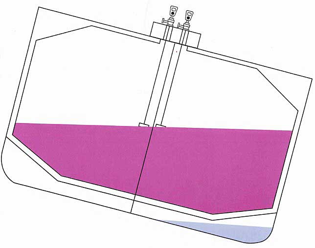
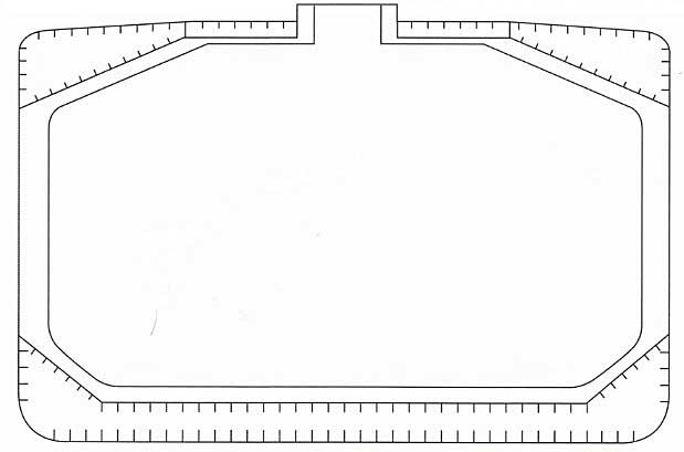
The tanks extend to nearly the full width of the ship, with ballast in the double bottom and upper hopper or wing tanks. The tanks normally have a centreline bulkhead fitted with two equalising valves. A degree of caution is necessary if these vessels develop a list alongside as the tanks carry a large free surface area. If the vessel has problems with the ballast or while levelling the cargo during loading, they can quickly list over to 2° or 3°.
When carrying LPG the hold space is inerted.
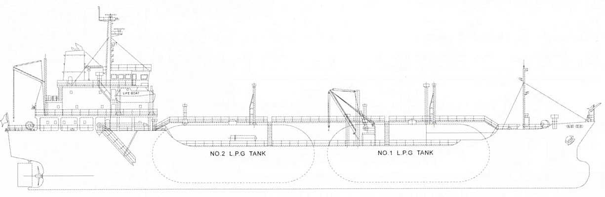
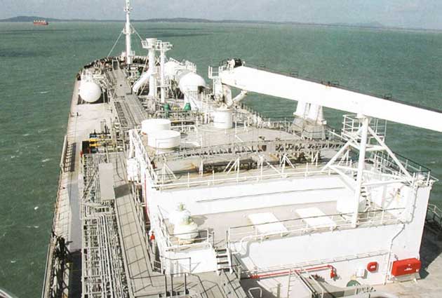
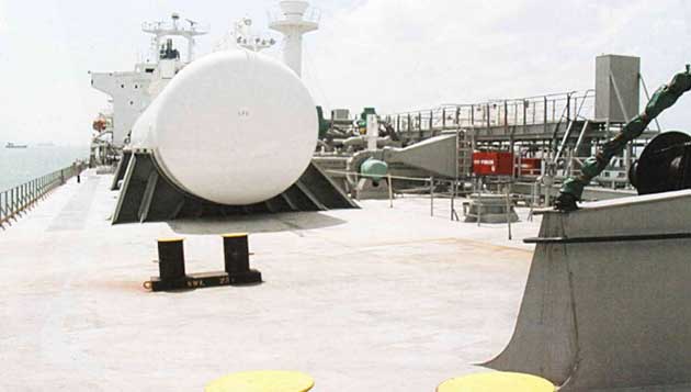
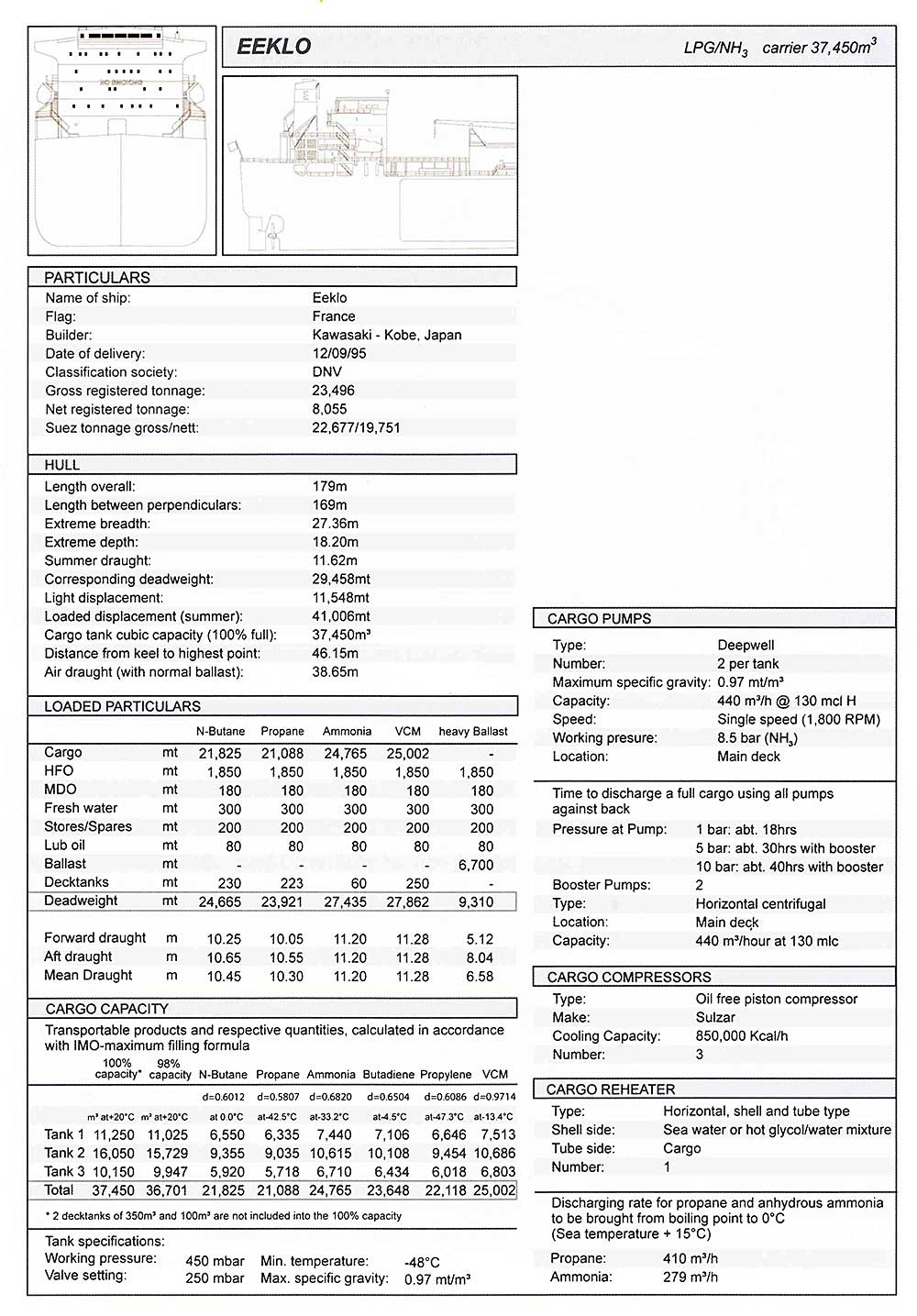
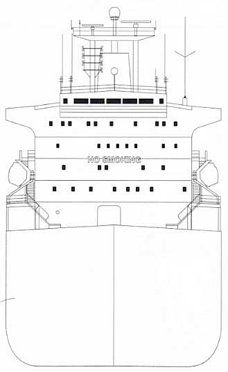
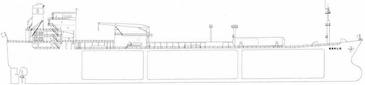
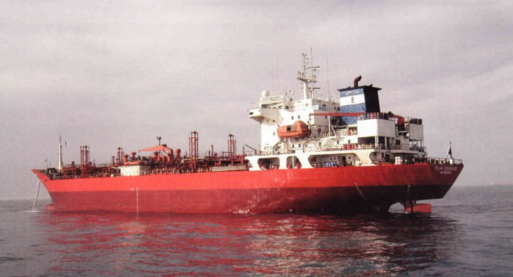
Example of a Fully Refrigerated LPG Carrier (37 450 m3)
Type “A” prismatic tank LPG/C “Eeklo”
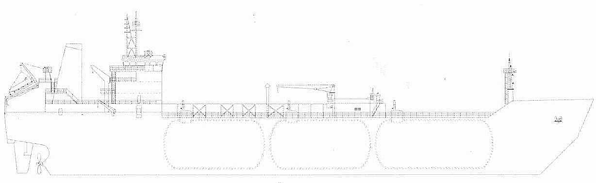
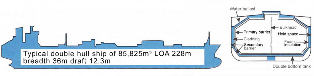
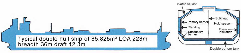
Example of a Fully-Refrigerated LPG Carrier (85 826 m3)
Type “A” prismatic tank LPG/C “Flanders Harmony”


Ethylene Carriers
Ethylene carriers are a special type of gas carrier that can transport ethylene fully-refrigerated at its atmospheric pressure boiling point of -104 °C. Such ships are often built for specific trades although many ethylene carriers can also carry LPG cargoes, increasing their flexibility.
Cargo capacity depends on the trade for which the vessel was constructed, but ranges from 1 500-15 000 m3.
Thermal insulation and a high capacity reliquefaction plant is fitted on this type of vessel.
Ethylene carriers have containment systems that can be either Type “C”, Type “B” or Type “A” prismatic free-standing.
- If Type “C” pressure vessel tanks are used, no secondary barrier is required.
- If Type “B” is used a partial secondary barrier is required.
- If Type “A” is used a full secondary barrier is required. Because of the cargo temperature of -104 °C, the hull cannot be used as a secondary barrier in this case and a separate secondary barrier must be fitted.
For reasons of economy, Type “C” tanks are the dominant type in this trade. Ballast is carried in a full double bottom and wing tank ballast system.
Example of an Ethylene Carrier (10 503 m3)
Type “B” Tank (sphere) Ethylene/LPG/C “Polar Belgica”
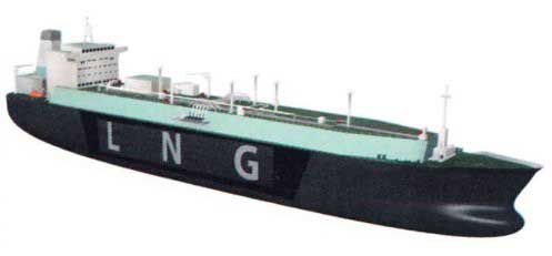
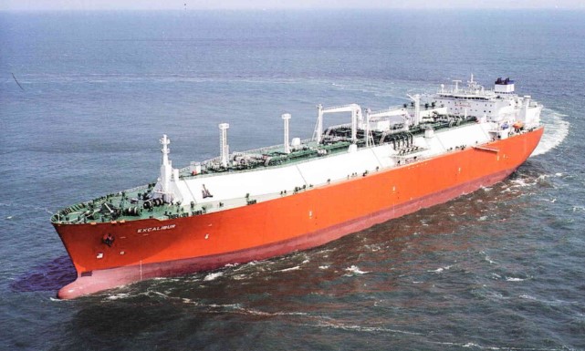
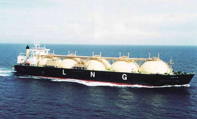
LNG Carriers
LNG carriers are specialised ships that transport LNG at its atmospheric pressure boiling point of approximately -161,5 °C. The ships are usually dedicated vessels, but some smaller examples may also carry basic LPG cargoes. If an LNG ship is capable of carrying basic LPG cargoes, a reliquefaction plant is installed to handle the boil-off LPG cargo vapours.
LNG carriers were typically in the range 80-135 000 m3 up until 2006.
In 2006 the first LNG ships of over 200,000 m3 were being constructed for the new LNG Qatar Production trains.
LNG is liquefied by refrigeration to -161,5 °C. This process is carried out ashore, before the cargo is loaded onto the ship.
In 2006, LNG carriers were fully insulated because it was not yet cost effective to liquefy methane on board. The first LNG carrier with a reliquefaction plant was placed on order in 2006.
As the ship has no reliquefaction plant, any boil-off vapours are burned as fuel gas in the engine room.
The cargo containment systems will generally be either:
- Membrane systems (GazTransporl I Technigaz) which are described in Liquefied Natural Gas and Liquefied Petroleum Gas Cargo Containment System“Membrane Tank Types”. (A full secondary barrier with inerted spaces is required for the membrane system) This system has a primary and secondary barrier that is constructed of a thin material and an insulation layer.
- Type “B” (Moss Rosenberg) (The Type “B” spherical tank, which is described in Liquefied Natural Gas and Liquefied Petroleum Gas Cargo Containment System“Type “B” Tank”, requires only a partial secondary barrier).
A full double bottom and side tank ballast system is fitted to all LNG ships.
Membrane (Gaz Transport or Technigaz)
(See Liquefied Natural Gas and Liquefied Petroleum Gas Cargo Containment System“Membrane Tank Types” for a more detailed description).
There are two membrane systems in use. In both cases the insulation is fitted directly into the inner hull and the primary barrier consists of a thin metal membrane less than one millimetre thick. The Gaz Transport system uses two such membranes constructed of “Invar” (36 % nickel-iron low expansion alloy).
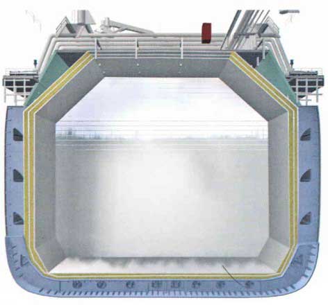
One acts as the primary barrier and the other the secondary barrier. They are separated by plywood boxes of perlite insulation. Similar boxes are fitted between the secondary barrier and the inner hull. Loading is transmitted through the insulation to the ship structure. No centreline division is possible in this type tank.
Gaz Transport style
The other system, developed by Technigaz, has a stainless steel membrane as the primary barrier while the secondary barrier is included in the insulation, which consists of load bearing balsa and mineral woods.
Gaz Transport and Techigaz are now known as “GTT” (Gaz Transport Technigaz) since the companies merged.

Spherical Tanks (Kvaerner Moss Rosenberg)
(See Liquefied Natural Gas and Liquefied Petroleum Gas Cargo Containment System“Type “B” Tank” for more detail).
The spherical tanks of this type of carrier are generally produced in aluminium or 9 % nickel steel. The sphere is welded to a steel skirt, connected to the hull of the ship, that is free to expand and contract as necessary. Insulation is fitted to the outside shell of the sphere but no secondary barriers is regarded as necessary across the upper part.
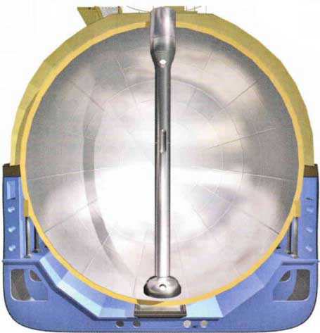
The Moss Rosenberg design has not been used on the larger LNG Carriers (200 000 m3+) to date (2006), due to poor utilisation of the inner hull space.
However, below the sphere, an aluminium drip tray, together with splash plates, provides secondary protection for the hull.
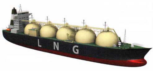
LNG Carrier Spherical Type “C” tank LNG/C “Galea”
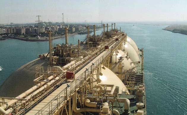
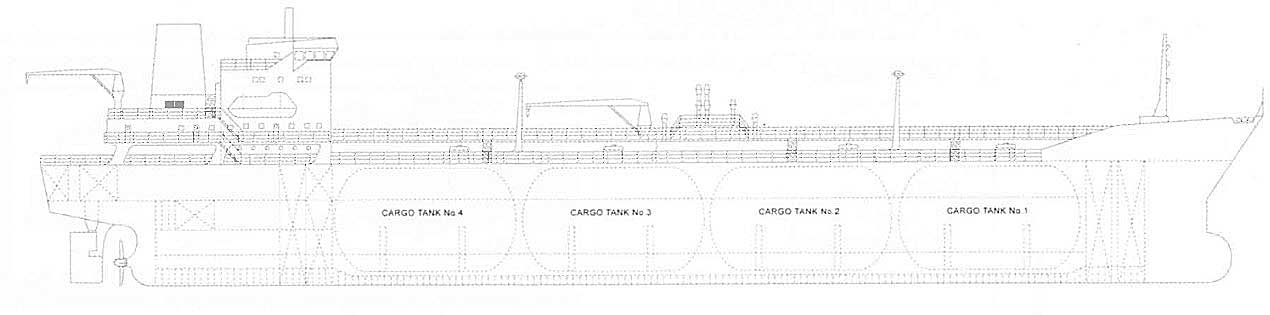
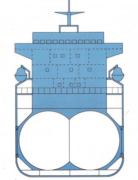
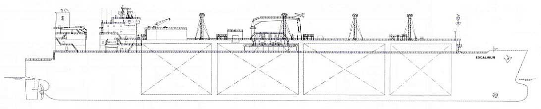
General Gas Carrier Layout
Gas carriers have many features that are not found on any other type of tanker. Cargo Handling Systems and Specialised Equipment on LNG LPG Carriers“Cargo Handling System used on Liquefied Gas Carriers” deals with cargo handling systems and highlights some of the basic differences. Some other very important features can be identified by looking at the general layout and arrangement of gas carriers.
It is not permitted to have a cargo pump room on gas carriers. No cargo pipework is permissible beneath deck level, so deep well pumps or installed submersible cargo pumps must be used for cargo discharge. Cargo pipework to tanks beneath deck level must be taken through a cargo tank dome, which penetrates the deck.
Where a gas tanker is fitted with a reliquefaction plant it is usually situated in a compressor house on deck, although some smaller ships have the compressor and condenser machinery in partially sheltered open deck areas. An electric motor room that contains the motors that drive the compressors, or the reliquefaction plant and booster pumps where fitted, is connected to the compressor house. The electric motor room and compressor room are separated by a gas-tight bulkhead.
The IMO Code details the requirements for the mechanical ventilation of these rooms. Positive pressure ventilation must be provided for the electric motor room, with negative pressure ventilation for the cargo compressor area ensuring a positive pressure differential between the two.
An airlock entrance from the weather deck to the electric motor room, with two gastight doors at least 2 m apart, prevents loss of the pressure differential provided that both doors are not opened simultaneously. The doors must be self-closing, with the audible and visual alarms on both sides of the airlock set to alarm if both doors are opened simultaneously.
In addition, any loss of the pressure differential in the motor room should trip the electric motors. These protective systems are fundamental to the safety of a gas carrier. Another safety feature used in the motor/compressor room area is the sealing of the driving shafts that penetrate the gastight bulkhead between the compressor and the motor room.
Cargo tanks cannot be used for ballast purposes on gas carriers and so separate ballast tanks are employed.
The cargo containment and handling systems must be completely separate from accommodation spaces, machinery spaces, etc, with cofferdam separation or other means of gastight segregation between the cargo area and the engine room, fuel tanks and chain lockers. The IMO Code provides specific recommendations about positioning doors from the accommodation space into the cargo areas.
In addition, air intakes for accommodation and engine spaces must be sited al a minimum specified distance from ventilation outlets that are associated with gas dangerous areas. All air intakes into the accommodation and service spaces should be fitted with closing devices.
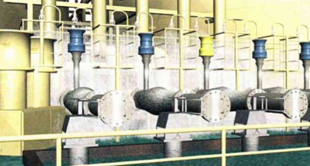
Gas tankers should be fitted with a fixed water spray system for fire protection purposes. This should cover cargo tank domes, cargo tank areas above deck, manifold areas, front of the accommodation area, boundaries of rooms facing the cargo area, etc. Minimum water flow rates of 10 litres per m2 per minute for horizontal surfaces and 4 litres per m2 per minute for vertical surfaces should be achieved.
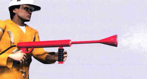
As well as a fixed water spray system, all gas carriers must be fitted with a fixed dry powder installation capable of fighting cargo area fires. At least two hand hose- lines must be provided to cover the above- deck cargo area, including above-deck product piping. The dry powder installation is activated by nitrogen, which is stored in pressure vessels adjacent to the powder containers.
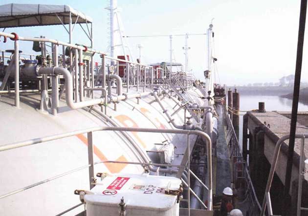
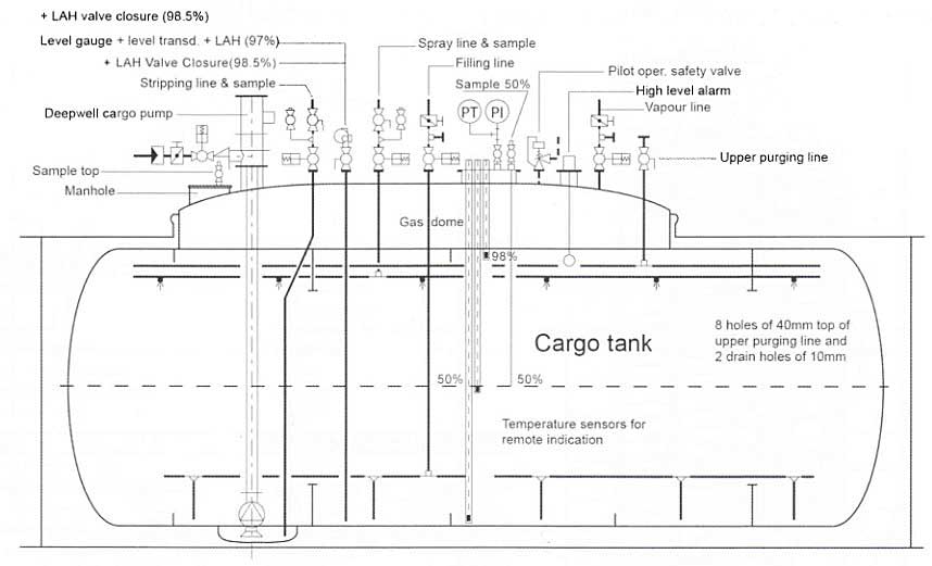
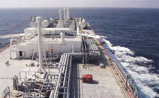
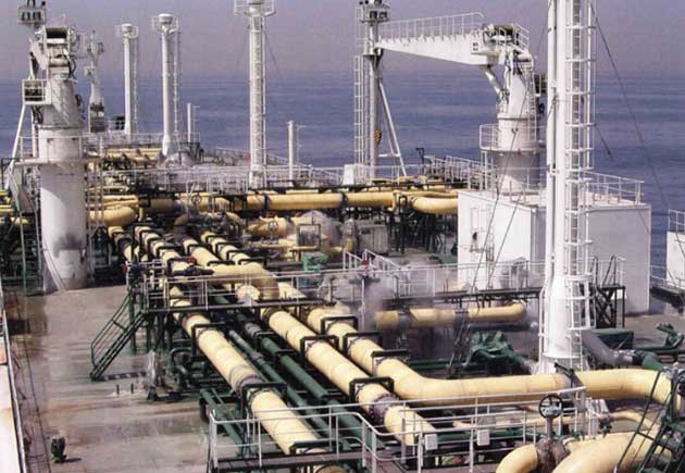
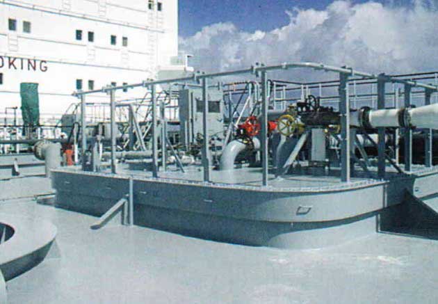
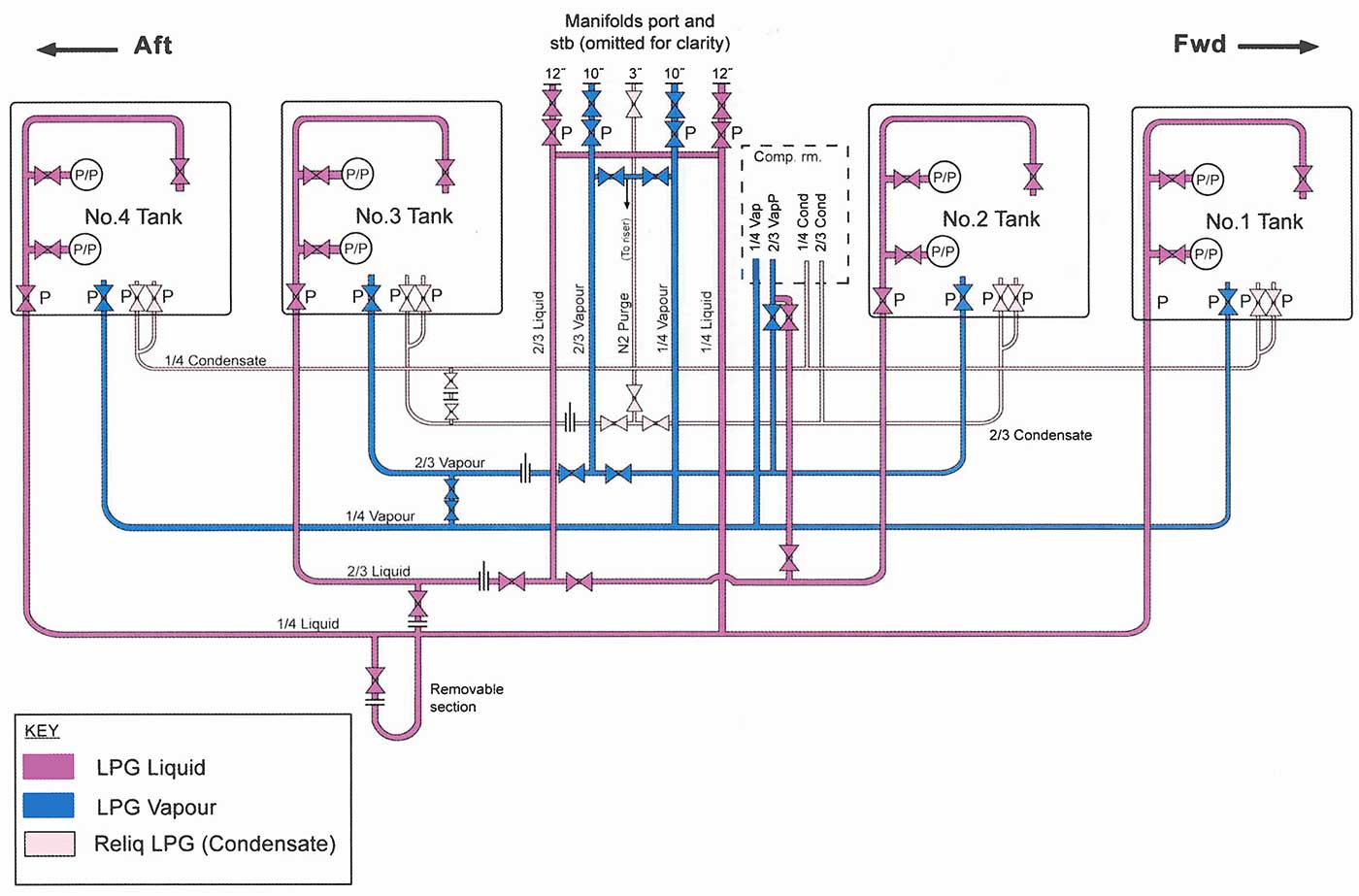
General Layout of the Deck Piping on a Fully Refrigerated LPG/Carrier
Categorisation of Gas Ship Types
The IMO Code recognises three categories of gas carrier:
- IG – this carries substances with the greatest environmental hazard, such as chlorine. It will have the most stringent set of construction standards to meet damage survival requirements.
- IIG – (which has a sub-category of IIPG). This carries substances with a lower environmental hazard and, while, construction standards are still rigorous, does not have as high a damage survival requirement.
- IIIG – this carries the lowest environmental hazard substances and, while still with a high construction standard, has the lowest requirements for damage survival in the event of collision or grounding.
As an example, a fully-refrigerated ship carrying LPG with type A tanks must comply with the standards for survival capability of a IIG ship. A semi-refrigerated ship with type “C” tanks could comply with either a IIG or IIPG. If the IIPG compliance is selected, then the pressure vessels must have been designed with a Maximum Allowable Relief Valve Setting (MARVS) of 7 kg/cm2 and a temperature of not less than -55 °C.
The category takes into account the survival capability and reserve buoyancy of the containment system and the IMO Code should be referred to for the detailed construction requirements of each ship type.
Surveys and Certification
The IMO Code specifies three different surveys for gas carriers, as follows:
- An initial survey before the ship is put into service, or before issuing a Certificate of Fitness for the first time. The survey must include the structure, equipment, fittings, arrangement and materials of the ship and it is to ensure that the ship complies with the IMO Code. (International Code for the Construction and Equipment of Ships Carrying Liquefied Gases in Bulk – the IGC Code).
- Periodic surveys, at intervals not exceeding five years, to ensure that structure, equipment, fittings, arrangement and material fully comply with the provisions of the Code.
- Intermediate surveys, at intervals of 30 months, to ensure that basic safety equipment, pumping and piping systems etc. comply with the Code and are in good working order. Intermediate surveys are endorsed on the Certificate of Fitness.
An annual inspection of compliance with the Certificate of Fitness requirements will take place and there is also always the possibility of a random inspection by interested authorities, such as Port State or Flag State Inspectors.