Explore the characteristics of LNG and LPG tankers with our comprehensive guide covering rules, regulations, design, construction, and operation.
From cargo equipment to safety protocols like emergency shut-down systems, discover the essentials for crewing and operating these specialized vessels.
General
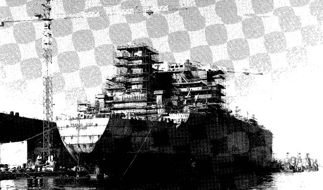
Liquefied Petroleum Gas (LPG) Tankers are very similar, in terms of general equipment, to the sophisticated chemical tankers or parcel tankers. They are, as a matter of course, built with high quality materials and fitted with a high level of navigation and communication equipment. Because of the high value of the cargo containment system and other cargo equipment, the ships are expected to last for many years and particular attention is paid to the quality of hull construction and the general corrosion protection. As maintenance of the hull integrity is the key to ship longevity, the corrosion protection of these ships is usually the object of constant regular attention during the ship’s life.
Liquefied Natural Gas (LNG) Tankers are slightly different, particularly where their machinery is concerned. As the LNG boil-off is lighter than air at ambient temperature, it has been found convenient to use it as fuel in the ship’s machinery and burning it in boilers has, up to now, been found the most practical way of using this available fuel. Onshore installations, natural gas is currently used in diesel engines and gas turbines but this type of machinery has not yet found favour with ship operators.
This is why, to date, all LNG ships but two are equipped with boilers, steam Exploring Different Turbine Propulsions for Liquefied Gas Carriersturbo generators for electrical production and steam turbines for propulsion. Furthermore, because the cost of these ships is even higher than that of the LPG ships, more reliability and a longer life is expected from them and better materials and more precautions are used for their construction.
Rules and regulations
Design and construction
Ship design and construction are controlled by a set of comprehensive international rules which are universally accepted. For very specialised ships, such as liquefied gas tankers, the rules are very far-reaching and include detailed coverage of cargo containment systems and other cargo equipment.
These rules are mainly laid down by the International Maritime Organization (IMO). The most important are incorporated in the International Convention for the Safety of Life at Sea (SOLAS), covering the following subjects:
- Chapter 1 – General Provisions.
- Chapter 2.1 – Design and Construction – Hull, machinery and electrical installations.
- Chapter 2.2 – Design and Construction – Fire protection, detection and extinction.
- Chapter 3 – Life saving appliances and their arrangements.
- Chapter 4 – Radio communications.
- Chapter 5 – Safety at sea and navigation.
- Chapter 7 – Carriage of dangerous goods – Construction and Equipment of Ships Carrying Dangerous Liquid Chemicals in Bulk and Construction and Equipment of Ships Carrying Liquefied Gases in Bulk (IGC Code).
- Chapter 9 – International Management Code for the Safe Operation of Ships and for Pollution Prevention (ISM Code).
Rule application is controlled and supervised by the Flag State of the ship. A ship’s conformity with the rules is confirmed by the delivery of the following certificates:
- Load Line Certificate.
- Safety Construction Certificate.
- Safety Equipment Certificate.
- Safety Radio Equipment Certificate.
- Certificate of Fitness for the Carriage of Liquefied Gases in Bulk (or dangerous chemicals in bulk).
- Safety Management Certificate.
- MARPOL Certificate.
Some Flag States carry out their own inspections and administer their own certification process. However, most Flag States delegate some or all of these tasks to Classification Societies which are then empowered to deliver the certificates in the name of the Flag State.
Classification Societies have included all the SOLAS regulations into their own classification rules. They clarify and complement these rules with their own additions and interpretations. These are mainly detailed considerations on construction materials, strength and buoyancy calculations, types of equipment for each type of ship.
To confirm the application of these detailed rules, Classification Societies deliver their own Classification Certificates for hull, machinery and cargo equipment.
All the certificates, whether issued by Flag States or Classification Societies, must be kept valid throughout the active life of the ship by means of periodic inspections. The interval between inspections varies from one year, for the simple ones, up to five years for the more comprehensive checks. The five-year surveys, the so-called Special Surveys, include complete internal re-inspection of most parts of the ships, with detailed checking of the hull thickness, internal condition of the tanks and demonstration of the good operation of all machinery, including electrical, cargo, navigation and communication equipment.
Operation and crewing
As in the case of ship design and construction, ship operation and crewing are guided by comprehensive sets of International and National Rules.
The new International Management Code for the Safe Operation of Ships and for Pollution Prevention, the ISM Code, now included in Chapter 9 of SOLAS, came into force in July 1998 for certain vessels, including liquefied gas tankers. It gives guidance for establishing methods for the organisation, administration and operation of the ship operating company. These rules are applicable to shore operating offices as well as to ships at sea. After establishing procedures and issuing operating manuals as required by the ISM Code, operating companies and ships must be audited at regular intervals by a representative of the Flag State for confirmation that the rules are known and applied by all members of the company. The ISM Code includes crewing procedures, hiring practices, conditions on board, levels of responsibility, health and safety, etc. which should be clearly specified in the company instructions and regularly enforced. Among other items covered by the ISM Code are:
- cargo handling;
- maintenance;
- communication between ship and shore;
- protection of the environment;
- master’s responsibility.
The ISM Code requires that specific procedures and contingency plans be established for different types of emergency situation, including those involving cargo. All personnel on board and in the company offices ashore must be aware of these procedures and trained in applying the contingency plans. The Code requires that operating companies nominate a representative to be personally responsible for the application of the ISM Code.
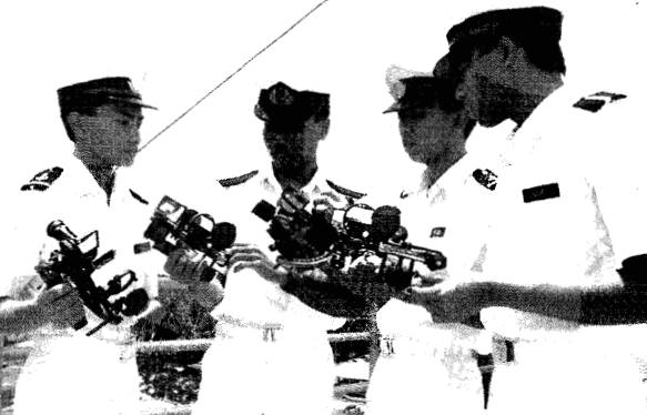
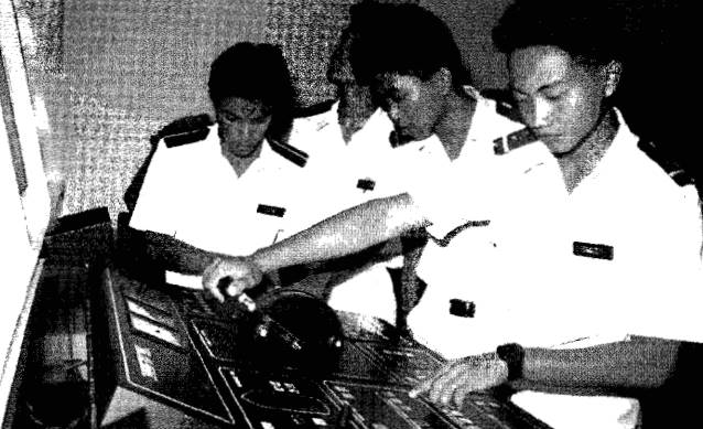
The International Convention on Standards of Training, Certification and Watch-keeping for Seafarers 1978, as amended by the 1995 STCW Convention, specifies the minimum level of education, experience and training required from officers and ratings on board. Ideally, a liquefied gas ship operator will insist on a standard higher than this minimum. The ship’s total complement is specified by National Administrations and is based on the ship operation, both day-to-day and in an emergency situation, bearing in mind the internationally recognised hours of work. The STCW Convention also discusses proficiency in a common language, maximum hours of work and minimum resting time, general health policy, etc. All the requirements of STCW must be incorporated in the ISM procedures mentioned previously.
Chapter 5 of SOLAS controls safety at sea and navigation. Chapter 7 deals with cargo and safety operations on gas and chemical tankers through the BCH and IGC Codes.
The International Convention for Prevention of Pollution from Ships (MARPOL) has been developed following the serious pollution incidents created by large oil tankers in the 1960’s and 1970’s and it is administered by the International Maritime Organization (IMO). Annex 1 covers oil pollution from ships. This can have implications for ship bunkering operations. Annex 2, which is in preparation, will cover pollution from cargo which, most of the time, will not directly affect gas tankers. Future additions to MARPOL will relate to quality of discharged ballast waters and air pollution caused by ships.
Cargo equipment
Pipes and valves
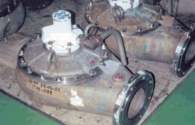
Pipes and valves play a very important role on a liquefied gas tanker. The cargo piping is necessary to load and discharge the cargo in port and to maintain the cargo in good condition whilst at sea. The water-ballast piping is necessary to load and discharge ballast water to ensure the stability of the ship. The fire-fighting and spray-water piping are necessary to ensure the safety of the ship in case of fire. The general piping is necessary for all other general operations on board.
The cargo piping and valves are made of materials suitable for the minimum temperatures, maximum pressures and chemical characteristics of the products to be handled. The piping system must be suitably supported and equipped with expansion loops or bellows to compensate for movement due to changes in temperature. The manifolds are used to receive the shore connections for loading and discharging the cargo. There is usually a sufficient number of liquid and vapour manifolds to completely separate the different products that the ship can carry. A remotely actuated isolating valve, the Emergency Shut-Down (ESD) valve, is fitted at the end of each manifold. A similar valve is also fitted at the end of the shore side piping. In case of incident, the ship or the shore can close the two valves remotely to stop the flow of cargo and prevent any leakage. One or several liquid and vapour headers link the manifolds to the tanks with an isolating valve at the connection with each tank. Separate piping networks link the tanks to the reliquefaction equipment, often combined with the spraying/cooling equipment, also to the inerting and aerating system. Each cargo tank and cargo hold or insulation space is fitted with pressure relief valves directly connected to venting masts. Finally, there is the necessary small piping for the control and instrumentation systems.
The network of water-ballast piping and valves are made of materials showing a good resistance to sea-water corrosion. It allows all ballast tanks on the ship to be filled or emptied at the same time or one by one through pumps located in the engine room or by gravity directly from the sea. The time necessary to fill or empty the ballast tanks is usually based on the time necessary to load or discharge the cargo.
The fire-fighting and water-spray piping and valve networks, also made of materials resistant to sea-water corrosion, must be fire resistant as well. Fire pumps in the engine room provide a good flow of water to the fire-fighting piping, with sufficient pressure to reach all parts of the ship, including the highest point. The spray-water piping network is also supplied by a pump in the engine room. It covers the:
- cargo tank domes;
- the cargo manifolds;
- the cargo machinery and control room,
the front of the accommodation and the life boats boarding area with a specified quantity of sea-water to help keep all these areas cool in case of fire. It is also used to protect the ship’s structure in case of a drop in temperature resulting from cargo leakage and to assist in the vaporisation of leaked cargo.
Reliquefaction plants
Fully-pressurised gas carriers can accommodate the maximum pressure that the cargo will reach during the voyage. LNG carriers use the cargo boil-off as fuel, thus maintaining the tank pressure and temperatures at the required level. All other semi-pressurised and fully-refrigerated LPG carriers must be equipped with reliquefaction plants to control the cargo pressure during the voyage. There are two main types of reliquefaction plant, both designed to perform the following functions:
- Cool down the cargo tanks and associated pipelines before loading.
- Reliquefy the cargo vapour generated by flash evaporation, liquid displacement and boil-off during loading.
- Maintain cargo temperature and pressure within the required levels by reliquefying the boil-off vapour.
a) Indirect Cycle – In this system, the cargo vapours are refrigerated and condensed by an external refrigeration system, without being compressed. There are not many ships equipped with such a system, as it requires much greater refrigeration capacity than the direct cycle systems
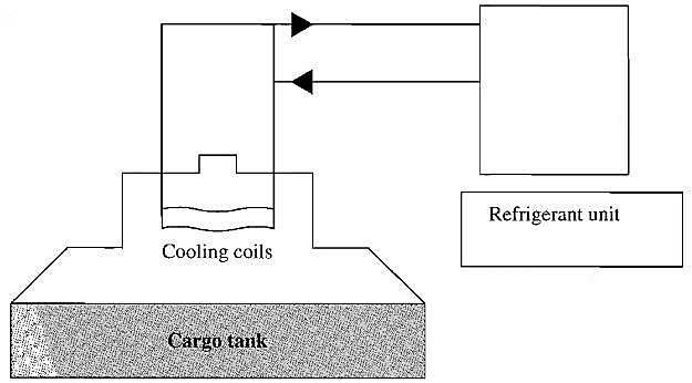
However the IMO Gas Code requires this type of refrigeration for the carriage of:
- Chlorine.
- Ethylene oxide.
- Propylene oxide.
b) Direct Cycle – In this system, the cargo vapours are compressed, condensed and returned to the tank. It is the system found on most ships but it cannot be used with certain gases. Three different types of direct cycle reliquefaction plants are used:
- Single-stage direct cycle – Mainly found on semi-pressurised ships.
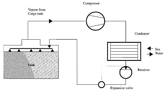
- Two-stage direct cycle – Not very common – The two-stage compression limits the compressor discharge temperature – Used for products such as butadiene and vinyl chloride.
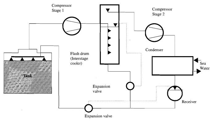
- Cascade direct cycle – Mainly used on fully-refrigerated ships.
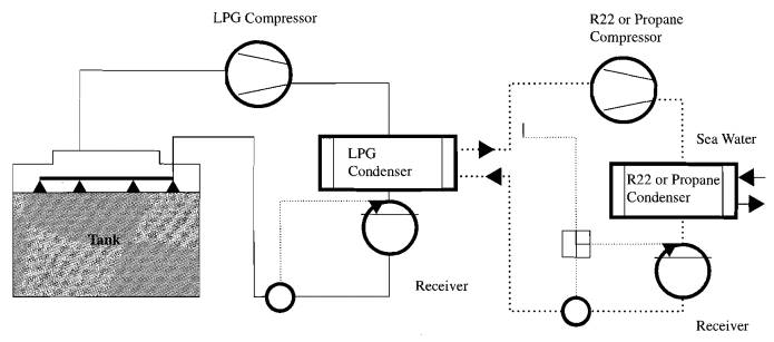
Up to now the refrigerant R22 was used for the first stage of the cascade. However, according to the Montreal protocol, this product will be phased out by the year 2020 at the latest. A recent trend is to use a closed circuit of propane instead of R22.
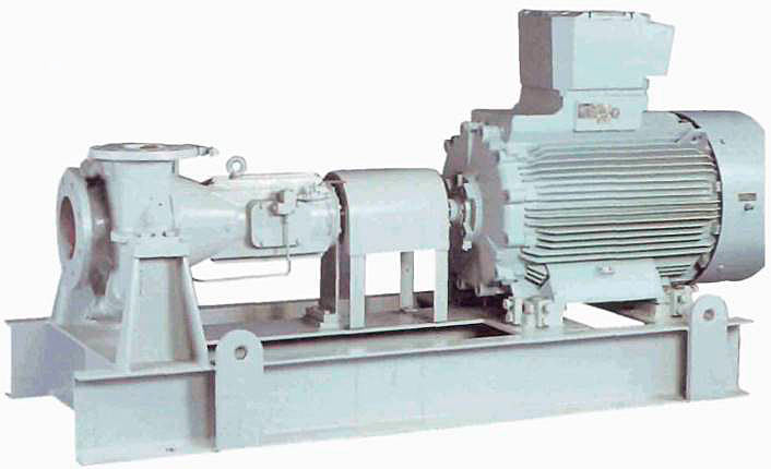
Pumps and compressors
Some fully pressurised ships are only equipped with compressors to discharge their cargo. They take vapour from one tank, compress it and push it to the top of the tank to be discharged. Most modern ships, however, have, in addition, one or more booster pumps to speed up discharging operations.
Semi-pressurised ships are all equipped with at least one deepwell pump per tank. This type of pump has the electric or hydraulic motor on top of the tank dome and a long shaft to drive the pump located at the bottom of the tank. The two critical points of these pumps are the tightness of the shaft inlet into the tank and the guiding of the shaft over its full length to avoid any vibration. In case of failure of one of the pumps, the compressors can be used, as described above for pressurised ships. On these semi-pressurised ships, except for the very occasional emergency discharge, compressors are used only for reliquefaction and during inerting/aerating operations. Most of the semi-pressurised ships are equipped with booster pumps and cargo heaters, using sea water as a heating medium, to allow the discharge of cargo at ambient temperature into pressurised storage.
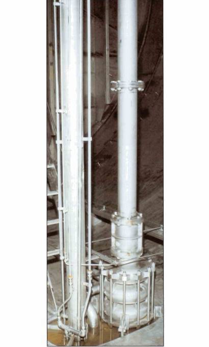
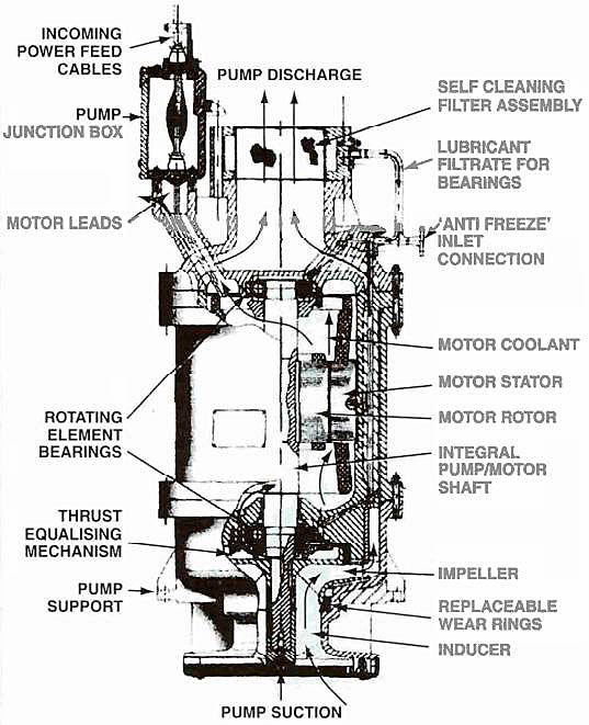
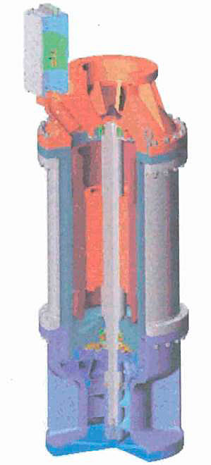
The Transportation of the Petroleum Gas and Amonia Cargoes on the Fully-Refrigerated LPG Shipsfully-refrigerated ships are equipped with either deepwell pumps or submerged pumps. Submerged pumps have the electric motor built into the pump in one unit which is located at the bottom of the tank. This is no problem for LPG, LNG and most of the petrochemical gases which are dielectric. For ships transporting ammonia, however, special types of submerged pumps are required. Due to the low tank pressure on fully-refrigerated ships, compressors cannot be used as an emergency discharging method. It is necessary to have two pumps per tank. On tanks with a longitudinal bulkhead, a foot valve allows the two halves to communicate and then one pump can discharge the whole tank. Another method is to have an emergency pump installed in a column equipped with a foot valve. The column can be emptied and inerted with nitrogen under pressure and, with the valve closed, the emergency pump can be installed. Submerged pumps are difficult to access for maintenance and, although they are normally very reliable, damage occurs very quickly if they are run dry, even very briefly. For very large LPG ships, a choice must be made between deepwell pumps with very long shafts or submerged pumps. Fully-refrigerated ships are also equipped with a cargo booster pump/heater combination to be able to discharge their cargo into pressurised storage, if required.
LNG ships are all equipped with two submerged pumps per tank. Membrane tanks are usually equipped with a tube to install an emergency pump in case of failure of the two pumps in one tank. If this happens on board a ship equipped with self-supporting tanks, it is possible, using the compressors, to raise the pressure in one tank sufficiently to discharge that cargo. This, however, is only permitted if the tanker is in calm waters.
Some of the petrochemical gases carried by LPG tankers can react with the lubricating oil used in the cargo compressors.
Mast ships use oil free compressors, where cylinders are not lubricated and the compressed gas is completely separate from the crankcase containing the lubricatidg oil.
Ships equipped with a two-stage reliquefaction system usually have a first-stage centrifugal compressor and a second-stage oil-free reciprocating compressor. Large ships are equipped with high-flow, centrifugal blowers to deal with cargo vapour and also to speed up the gas freeing/inerting operation. LNG ships are also fitted with high-flow centrifugal blowers to return cargo vapour ashore during loading, to deal with the boil-off at sea and to warm up the tanks prior to inerting.
Cargo quantity measurement – custody transfer
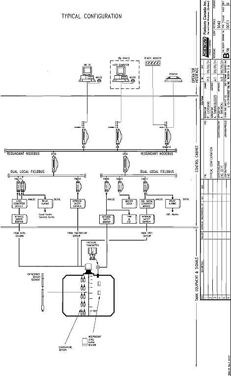
Cargo quantity measurement is a major concern on all liquefied gas ships as the quantity of cargo loaded or discharged is usually measured on board. During a ship’s construction, the volume of the Gas Freeing of Cargo Tanks on Liquefied Natural Gas Carrierscargo tanks is accurately measured by an expert surveyor, approved by the customs authority of the country where the ship is registered or where the cargo is regularly loaded or discharged. The tank calibration tables, usually showing the level at every centimetre, include corrections for temperature and for any list and trim. Each tank is equipped with level, pressure and temperature gauges which have a declared accuracy at the normal temperature of operation and which are regularly recalibrated under the supervision of an approved expert. Level gauges can be float, capacitance or radar type. The slip tubes used on early ships are no longer authorised as they could not operate without some cargo being released to the outside. Level readings are usually taken remotely and, on recent ships, they are processed through a computer. All necessary corrections are integrated and the final cargo volume or weight is calculated automatically.
The complete system is known as the custody transfer system and includes all equipment used to obtain the necessary measurements and calculate the results.
Calculations of cargo quantities done on board, most of the time under the supervision of an approved surveyor, are used to establish the commercial documents required by the ship owners and the cargo receivers.
Inert gas and nitrogen
The very high level of safety achieved by liquefied gas tankers is partly due to the fact that, when on board, the cargo is never in contact with air and, therefore, the chances of a fire or explosion are very remote. This is easily achieved during normal operation, when ships carry the same type of cargo over long periods. When, however, it is necessary to clean the tanks prior to the loading of a different type of cargo or to carry out repairs, the tanks must be opened and consequently air is introduced into the system. In such cases, inert gas is used to replace the hydrocarbon gas and remove the fire or explosion risks before the introduction of air.
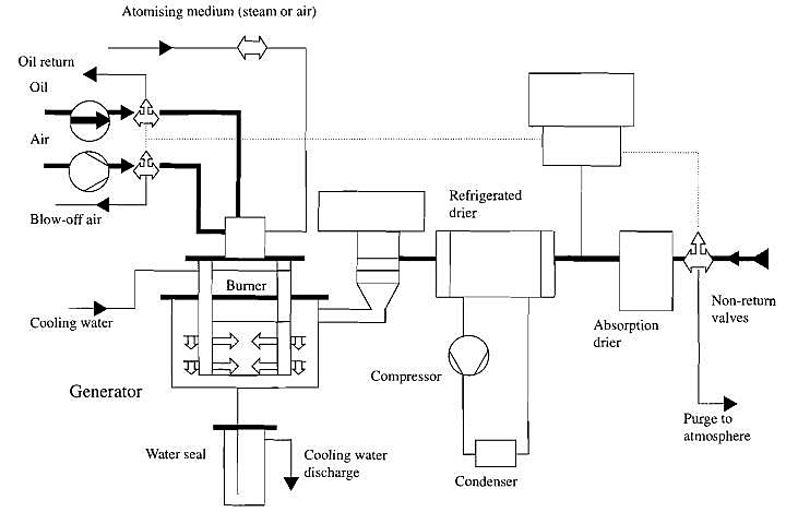
Inert gas is the exhaust gas resulting from the combustion of oil in a special inert gas generator. Low sulphur gas oil is used and special precautions are taken to ensure a controlled content of oxygen and pollutants, such as carbon monoxide (CO) or nitrogen and sulphur oxides (NOx, SOx). The size of the generator depends on the volume of inert gas required and this, in turn, depends on the size of the ship. Generators up to 15 000 m3/h are in operation. The inert gas produced is a mixture of mainly nitrogen with approximately 15 % of carbon dioxide, between 0,5 and 3 % of oxygen, a small amount of water vapour and traces of CO, NOx and SOx. The oxygen content can be adjusted as required, within certain limits, and the gas is passed through coolers and dryers to remove as much water vapour as possible before it is sent to the tanks. Theory shows that a mixture of hydrocarbon and oxygen containing less than 10 % to 12 % oxygen is not flammable. However, for safety reasons, inert gas with an oxygen content of around 3 % is generally used. When there is only a few percent of hydrocarbon left in the tanks, air can be introduced prior to opening the tank. Before loading a new cargo, the reverse operation is carried out. Air is displaced by inert gas until only a low percentage of oxygen remains prior to introducing hydrocarbon products into the tank.
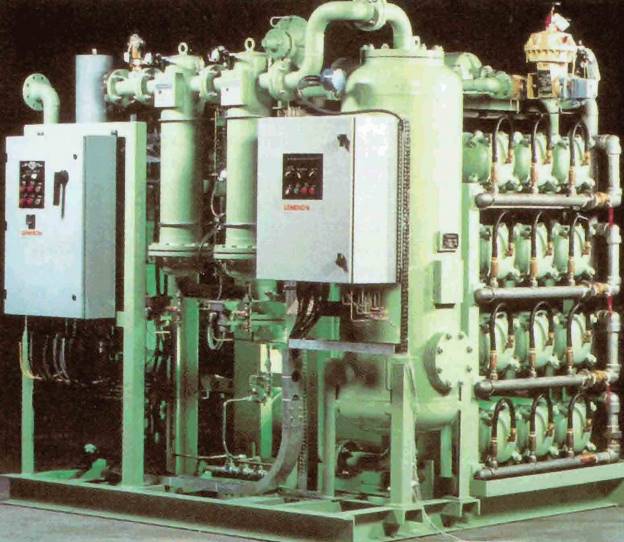
Some of the petrochemical gases react with oxygen and, in such cases, very low levels of oxygen are called for. When it is necessary to have oxygen levels below 0,5 %, pure nitrogen is used. This is usually delivered from shore in the form of liquid nitrogen which is vaporised before being taken on board. However, nitrogen can also be produced on board using nitrogen membrane generators. In these generators, compressed air is pushed through a special membrane which allows the nitrogen molecules to go through but retains the molecules of oxygen. These systems have seen a very rapid development in recent years and units capable of producing several thousand cubic metres per hour are now in service.
Ammonia reacts with carbon dioxide and inert gas cannot be used to displace ammonia. In early years, ammonia was directly removed by dry air. However, current practice is to use CO2-fiee inert gas either from shore or from a nitrogen membrane generator. This has the added advantage of avoiding the introduction of moisture into the tanks, which is always a possibility when using air.
On LNG ships, inert gas is used to displace methane before opening the tanks and also to maintain an inert atmosphere in the holds or insulation spaces around the tanks. However the carbon dioxide contained in inert gas freezes at -56 °C which is much higher than the LNG temperature of -162 °C. To avoid this problem, the tanks are warmed to ambient temperature prior to the introduction of inert gas for the displacement of methane and nitrogen is used to maintain the inert atmosphere wound the tanks. Up to 10 years ago, all LNG ships were fitted with a small tank of liquid nitrogen for this purpose and it was necessary to supply the ships with liquid nitrogen at frequent intervals. With the development of the nitrogen membrane generators, this is no longer necessary.
Safety equipment
Emergency shut-down systems (ESDS)
This is an important part of the safety equipment specific to liquefied gas tankers. The ESDS, if activated, will stop cargo pumps and compressors, shut down the gas burning on LNG ships and close designated cargo valves, including the manifold loading and discharge valves. The system can be activated by hand from various places in the cargo area or automatically through set points from the control system or, in case of fire, by melting plugs located in the cargo area.
The loading and discharging terminals are also equipped with an ESDS System designed to protect the shore loading/discharging arms and hoses and other equipment in case of a pressure surge from the ship or against possible drifting of the ship when connected alongside. The shore ESD system has usually two levels of safety:
- ESD1, activated when the ship’s movement is limited to a pre-set level and which stops pumps and compressors and closes the manifold valves on board and ashore;
- and ESD2, activated when the ship’s movement continues and risks damaging the arms.
ESD2 will automatically close the loading/discharging arms’ dry-break coupling valves and disconnect the dry-break couplings, protecting the arms from permanent damage.
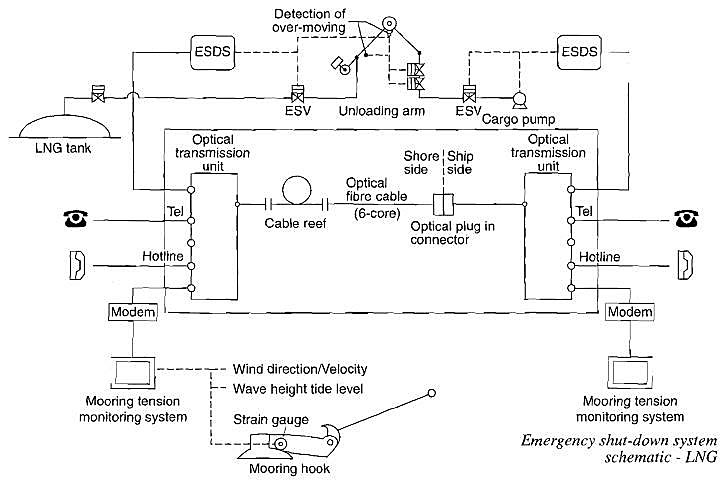
When a liquefied gas tanker is connected to a terminal, it is strongly recommended to link the ship and the terminal ESDS’s. If this is done, the ship can stop the terminal’s pumps in case of an incident during loading, the terminal can stop the ship’s pumps in case of an incident during discharging and the loading/discharging arms can be isolated and disconnected very quickly in case of unexpected displacement of the ship alongside the terminal, before a serious leak of cargo occurs. In the early years, the link between ship and shore ESD was made through an air pressure hose. In case of movement between ship and jetty, the hose would, in theory, be damaged and the loss of air pressure would activate the ESD. This was very basic and has now been replaced by transmission through electric signal, fibre-optic signal or radio signal. Small LPG terminals do not all have a linked ESD system but, in some terminals, the shore gives a pendant to the ship during loading and the ship gives a pendant to the shore during discharging. These pendants are an extension of each party’s ESD systems.
Read also: Piping System of pressure vessels on gas tankers
Large LNG terminals equipped with fibre-optic transmission can also use it for the connection of several voice and electronic transmission channels between ship and shore.
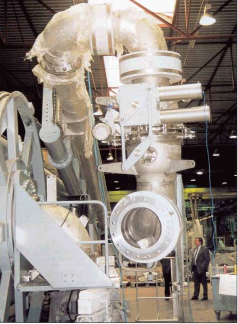
To assist connection and disconnection of the ship and shore cargo-piping, some terminals have hard arms equipped with Powered Emergency Release Coupling (PERC). This equipment replaces nuts and bolts to establish tight connections of the shore arm flanges to the ship’s manifold flange. It can be activated manually or hydraulically.
Hooks receiving the ship’s mooring lines on LNG jetties are equipped with automatic release couplings set to release at a certain level of line tension, to avoid the mooring lines breaking, should the ship’s mooring become unbalanced or overloaded due to strong winds and currents.
Other safety equipment
The IGC Code specifies in great detail the minimum inventory of safety equipment that must be carried by liquefied gas carriers. It is a comprehensive list and includes equipment for fire protection, fire-fighting, gas detection and individual personnel protection.
Engine rooms, cargo machinery rooms and accommodation must have fire detection equipment and fire alarms. The entrance to cargo electrical machinery areas must be equipped with special over-pressure ventilation systems, including fail-safe arrangements. There are provisions for stopping the whole ventilation of the ship from one central point. The water fire-fighting and water-spray systems must be remotely controlled and a fixed dry chemical powder system must be installed on deck for extinguishing gas fires. Gas analyses must be located at strategic points in the cargo area and other areas on board and must automatically warn of any presence of gas. Individual protection equipment must include:
- a specified number of self-contained compressed-air breathing apparatus;
- special chemical protection suits adapted to the cargoes carried;
- decontamination showers and eye-wash fountains;
- complete fire-fighting suits;
- individual gas and oxygen analyses;
- oxygen reanimation equipment;
- stretcher;
- portable ventilation fans, etc.
There should be evidence that all the safety equipment is in working order and properly maintained. The whole crew must be familiar with the operation of all this equipment and training exercises must be held frequently.