Ensure safe gas freeing of LNG cargo tanks with our detailed guide. Learn about inerting preparations, operational steps post-warming up, and key safety considerations to optimize your LNG carrier operations.
Reference: SIGTTO “LNG Shipping Suggested Competency Standards”, Sections:
1 Have an awareness of the principles of gas freeing:
- the method to be used to change tank atmosphere.
2 Know and understand the procedures for gas freeing:
- operation of inert gas generator to supply inert gas of appropriate quality;
- line up of cargo system to inert cargo tanks;
- line up and procedures to inert pipelines;
- criteria to be monitored during and upon completion of the operation, with specific reference to inert gas dew point temperature and relationship with cargo tank temperature;
- possible problems and causes, such as tank cold relative to inert gas dew point causing condensate formation;
- vapour pressure:
- likely behaviour;
- pressure control via boiler;
- precautions during pressure control via vent mast.
General
Inerting of the cargo tanks
After the tanks have been warmed up, the LNG vapour is displaced with inert gas (IG).
IG from the IG generator is introduced to the tanks from the bottom of the loading lines. The displaced LNG vapour is initially consumed by the ship’s propulsion system or the GCU. Once the CH4 percentage drops it is vented from the top of the tank via vent mast No. 1, or ashore if the ship is in port.
The inerting operation will continue until the hydrocarbon content in the tank is reduced to 2 % by volume.
In addition to the Cargo Containment Systems of LPG and LNGcargo tanks, the following equipment must be inerted:
| Special equipment | |
|---|---|
| Gas heaters | Forcing vaporiser |
| LNG cargo vaporiser | LD and HD compressors |
| Spray header | Spray pumps |
| Spray rail | Cargo pumps |
| Cargo lines safety relief valves | Cargo discharge lines |
| Manifolds, gas header | Tank gauging columns |
| Instrumentation boxes | Fuel gas supply line to the E/R |
| Emergency pump column | |
Ensure all “dead ends” are properly inerted. The operation will take about 20 hours. These points apply to the standard situation of venting to atmosphere while the ship is at sea. Fittings and lines are usually filled with IG or N2 while the plant supplies IG to gas free the cargo tanks. It is a multistage process that requires continuous planning and monitoring.
| Inerting operation | |
|---|---|
| 1 | Make sure that all warm-up parameters have been completed (as described in Efficient Liquefied Natural Gas Tank Warming Procedures“Procedures and Key Considerations of LNG Tank Warming Up) |
| 2 | Prepare to use IG plant in gas mode |
| 3 | Set the lines as defined in the procedure from the cargo operating manual |
| 4 | Before connecting the IG generator to the cargo system, start and run it until the O2 content and dew point have reached the recommended levels (O2 < 2 % and dew point < minus 45 °C (-45 °C)) |
| 5 | Monitor tank pressures and adjust the opening of the fill valves to maintain a uniform pressure in all the tanks. |
On Liquefied Natural Gas and Liquefied Petroleum Gas Cargo Containment Systemmembrane ships, ensure that tank pressures are always higher than insulation space pressures by at least 10 mbar, but not exceeding 180 mbar above atmospheric pressure. It is beneficial during gas freeing to keep the tank pressure low to maximise the “piston effect”.
- At about one-hourly intervals, take samples of the discharge from the vapour dome at the top of each tank and test for hydrocarbon content. On one of the tanks being inerted, open the purge valve on one of the filling lines to verify that the O2 content of the IG remains < 2 %;
- all unused sections of pipelines, blind ends, machinery, equipment and instrumentation lines must be purged;
- when the representative hydrocarbon content in a tank falls < 2 % by volume, isolate and shut-in the tank;
- on completion of tank and pipeline inerting, stop the IG supply and shut down the IG plan;
- reset the system for the aerating process.
Useful points
With the ship underway and venting, make sure the prevailing wind direction at all times allows the vapour to disperse away from the accommodation block and machinery intakes.
The “No Smoking” poster should be clearly located and enforced rigorously.
IG and pure N2 can be fatal. In order to avoid asphyxiation from O2 depletion, take great care to ensure the safety of all personnel involved with any operation that uses IG.
Read also: Safety Precautions and Measures on Gas tankers
Ensure there has been a risk assessment and that all personnel involved in the inerting procedure are familiar with the associated hazards.
Before the IG line is connected to the cargo system, blow it through with air. Use the IG blower to avoid any debris entering the cargo system.
Summary of inerting preparations
Preparations are as follows:
- a detailed plan of the operation must be prepared and risk assessment conducted;
- all portable gas detectors must be checked and calibrated prior to operation;
- prepare the IG plant for use in the gas mode;
- the spool piece must be fitted, connecting the IG line with the liquid header.
The line up of the cargo piping must be as per the ship specific cargo operating manual. Typically, it will be as follows:
- open the valves to supply IG to the liquid header;
- open the tank vapour valves;
- open the tank filling valves;
- line up the vapour header to No. 1 vent mast.
Operational description – cargo tank inerting after warming up
The flow loop directs IG from the IG plant to the liquid header and into the cargo tanks via the tank branch valves and the filling lines.
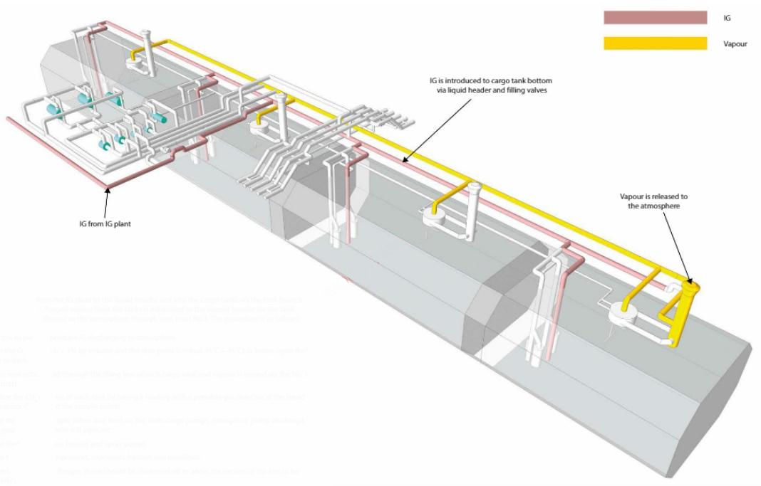
Purged vapour from the tanks is exhausted to the vapour header via the tank dome vapour valves and released to the atmosphere through vent mast No. 1. The procedure is as follows:
- start the IG plant to produce IG discharging to atmosphere;
- when the O2 content is < 1 % by volume and the dew point is minus 45 °C (-45 °C) or lower, open the valve to deck;
- flow is now established through the filling line of each cargo tank and vapour is vented via the No. 1 vent mast;
- monitor the CH4 content of each tank by taking a reading with a portable gas detector at the liquid and vapour domes and the sample points;
- purge through the sample valves and lines on the main cargo pumps, emergency pump discharge, float gauge column, racial still pipe, etc.;
- purge through the spray header and spray pumps;
- purge through the compressors, vaporisers, heaters and manifolds;
- where there are blank flanges, these should be slackened off to allow the section of the line to be properly inerted;
- when the CH4 content measured in the cargo tanks is < 2 % by volume, change over the IG flow to atmosphere and then close the tank filling and vapour valves;
- when all the tanks are inerted, stop the IG plant;
- close the IG supply valve to the liquid header and close the venting system at No. 1 vent mast.
Further considerations
When inerting cargo tanks after warming up, it is much easier to achieve the “piston effect” than with the air displacement after dry-dock as the difference in density of two mediums after warming up is greatly increased.
During the inerting procedure, the pressure in the tanks must be kept as low as possible to maximise the “piston effect”. However, the initial flow should be reduced to allow gradual filling to the tank bottom. This can be done for the first hour of the operation. Afterwards, the IG flow should be increased to the maximum.
All sampling points should be checked throughout the operation. If, at an early stage of the inerting operation (first 3 hours), a reduced CH4 content is observed anywhere other than at the bottom of the tank, it will indicate that the “piston effect” may not have been fully achieved and the operation may take longer than planned.
With the LNGC underway and venting, make sure the prevailing wind direction allows the vapour to disperse away from the accommodation block and machinery intakes.

- The international group of liquefied natural gas importers (GIIGNL). LNG custody transfer handbook / 6th Edition: 2020-2021.
- ©Witherby Publishing Group Ltd. LNG Shipping Knowledge / 3rd Edition: 2008-2020.
- CBS Publishers & Distributors Pvt Ltd. Design of LPG and LNG Jetties with Navigation and Risk Analysis / 4th Edition.
- NATURAL GAS PROCESSING & ITS ENERGY TRANSITION ROLE: LNG, CNG, LPG & NGL Paperback – Large Print, November 14, 2023.
- OCIMF, ICS, SIGTTO & CDI. Ship to Ship Transfer Guide for Petroleum, Chemicals and Liquefied Gases / 1st Edition, 2013.
- The Society of International Gas Tanker and Terminal Operators (SIGTTO). Ship/Shore Interface / 1st Edition, 2018.