Marine propulsion turbines have undergone significant advancements, paving the way for enhanced efficiency and sustainability in maritime operations. From Ultra Steam Turbines (UST) harnessing the power of steam to Gas Turbines offering rapid acceleration, the landscape of propulsion technology is evolving rapidly.
Innovations like Steam Turbine and Gas Engine (STaGE) systems combine the benefits of both steam and gas propulsion, while COGES (Combined Gas and Electric) configurations optimize fuel consumption. Understanding these cutting-edge technologies is essential for navigating the future of marine propulsion.
Ultra steam turbine (UST)
The UST was introduced to enhance the plant efficiency of steam turbine propulsion systems.
The design is based on a reheat cycle, where the steam used in the HP turbine is reheated to improve its efficiency. This improvement in the steam adaptation maintains the benefits of the simple steam-turbine while improving overall engine efficiency.
Traditionally, marine steam propulsion plants operate at turbine inlet steam conditions of 60 bar and +51 °C, while the UST plant operates at 100 bar and +560 °C, operating on a reheat/regenerative cycle.
The reheating cycle was added to improve thermodynamic efficiency. An intermediate pressure (IP) turbine section is incorporated in addition to HP turbines. It is expected that this development will enhance the efficiency of a steam ship by about 15 %, but will still be lower than other solutions with diesel engines.
The limitations in output power and the space required for a steam turbine propulsion system must also be considered.
The UST plant is equipped with reheat boilers and one intermediate pressure turbine for the regenerative cycle to improve the efficiency. Manufacturers claim the new UST plant is able to achieve 12 % plant efficiency improvement over a conventional steam plant.
The UST plant is a 2-stage feed water heating system based on the reheat cycle, ensuring a simple configuration with improved efficiency, operability, and maintainability. A comparison with the conventional steam turbine (CST) plant is shown below.
| Plant | CST | UST |
| Boiler steam conditions | 6 MPA @ +515 °C | 10 MPA @ +560 °C |
| Steam flow | Boiler > HP turbine > LP turbine > condenser | Boiler > HP turbine > reheater > IP turbine > LP turbine > condenser |
| Flange standard | ANSI 900LB | ANSI 2500LB |
The steam conditions of the marine UST plant were determined considering the actual performance and cost effectiveness of land use natural circulation boilers, as well as the scope of the ANSI 2500LB flange.
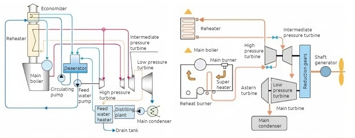
An outline of the arrangements of a UST plant are shown below. The space required is comparable with that required for a conventional steam turbine plant.
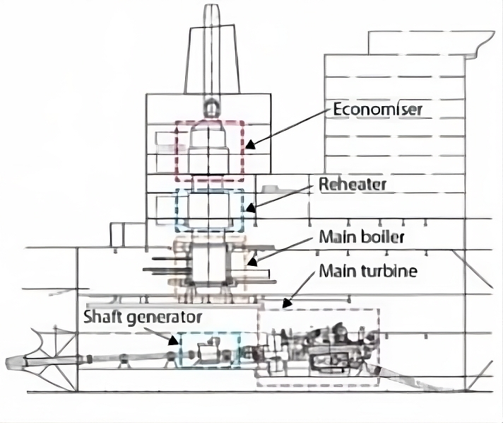
The UST turbine is a high performance unit that has a proven record in land use. It consists of a high/intermediate pressure turbine, a low pressure turbine, a main condenser and a reduction gear unit located in a single casing and on a single shaft.
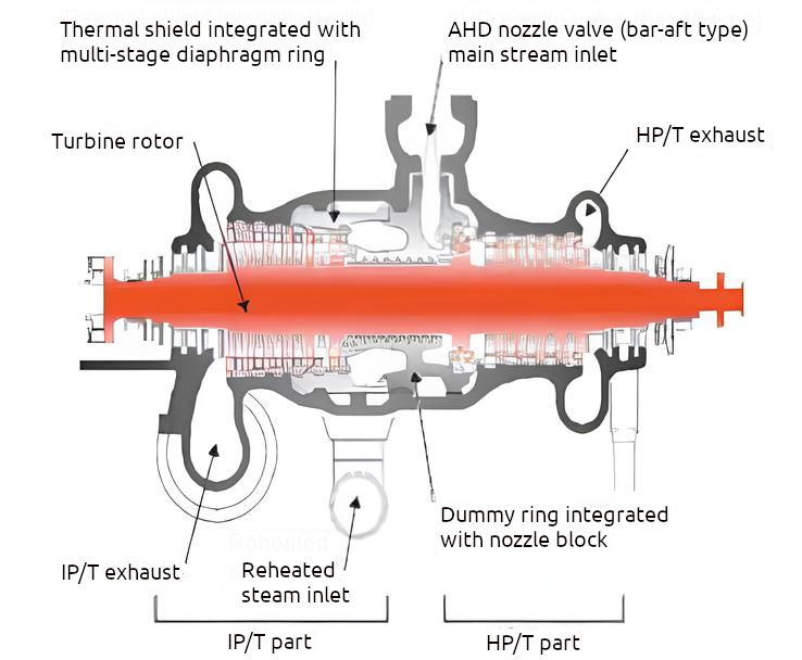
While HP and IP turbines are located in the same single casing, the operation of the UST turbine in ships is different from a land use turbine as it requires both start and stop operations and the HP/IP turbine casing, in particular, will be subjected to repeated thermal loads.
The difference between HP turbine inlet steam temperature and LP turbine inlet steam temperature could cause uneven deformation of the casing and consequent steam leakage from the horizontal flange of HP/IP casing. To alleviate this problem, a thermal shield structure is applied.
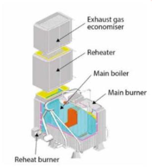
A re-heater unit is incorporated and the reheat burner stops automatically in low steam flow conditions so that the tubes are not exposed to high temperature combustion gases. High reliability is to be expected over long-term operation as there are no moveable parts, gas damper, etc. in the flow path of the combustion gas.
In order to improve efficiency and redundancy, in one proposed UST system a shaft generator motor (SGM) would be located on the intermediate shaft. Under normal operation, the SGM would be used as a generator to improve the plant efficiency (SG mode). If the operator wants 100 % MCR power when one re-heater is out of service, the SGM can be changed to assist motor mode (PAM mode) and the propulsion power will be recovered to 100 % MCR.
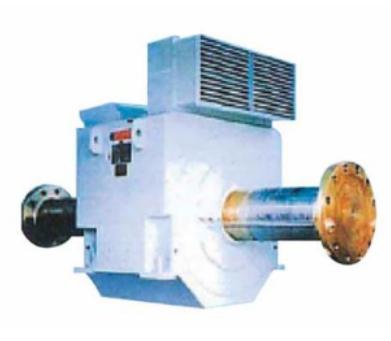
The UST plant can achieve an improved efficiency, while maintaining high reliability, which is the primary advantage of conventional turbine ships.
Comparison of advantages/disadvantages of ultra steam turbine plant
| Ultra Steam Turbine Plant | |
|---|---|
| Advantages | Disadvantages |
| Maintenance requirements in service, very low and usually achievable by ship’s staff | Limited number of UST marine steam turbine manufacturers |
| Downtime in port rarely required | Current design only allows for single screw ships |
| Flexibility of fuel selection: burning any fuel combination, oil only, gas only and dual. Full-load steam dump systems manage cargo boil-off requirements | Limited manoeuvring flexibility due to high inertia characteristics, with insufficient astern power to pull the ship free of ice |
| Uniform torque under load | Limited experience on the UST plant |
| Low lube oil cost | Availability of experienced service engineers |
| Large power to weight ratio | Relatively large ER volume required, reducing cargo carrying capacity |
| Reliquefaction plant and GCU not required | High rotor speeds require reduction gearing to the propeller shaft |
| Higher plant efficiency with about 15 % improvement in fuel consumption compared to a CST | Turbine is not directly reversible, an astern turbine is required |
| About 15 % decrease in emissions (NOx, SOx, CO2) | Limited shipyard experience of UST installations for refit |
| Manufacturers estimate extremely long plant life: operational for more than 40 years | |
| No redundancy is required for the steam turbine, gear box or propeller | |
Gas turbines
A gas turbine consists of a turbine and compressor connected to a single shaft. The High Duty Compressor(s) on the Liquefied Natural Gas Carrierscompressor delivers pressurised air to the combustion chamber where the fuel mixture is burnt. The combustion gases leave the combustion chamber and enter the gas turbine. The construction of the gas turbine/blading assembly is similar to that of a steam turbine, but the blading arrangement on modern gas turbines is constructed of special alloys to allow operation at temperatures of up to +2 000 °C.
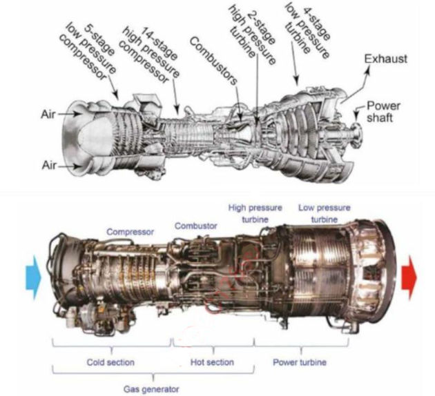
Fuel burns in the turbine engine’s combustion chamber at temperatures up to +2 000 °C, so a sophisticated cooling system is required. There is a heat cooling air system in each high-pressure turbine blade that is equivalent to a domestic air-conditioning unit.
At full output a gas turbine can suck in more than 1 tonne of air per second and, by the time the air leaves the nozzle at the rear of the engine, it has been accelerated to a speed of 1 690 kph.
The primary fuel for the gas turbine is cargo BOG, supplemented with force vaporised LNG if required. Marine gas oil will provide a secondary fuel source when BOG is not available (voyages to/from dry dock, etc.).
A two-passage fuel injector, diesel and gas, allows both fuels to be burnt simultaneously and enables the engine to maintain power output while changing fuels or burning a blended mixture of gas/liquid.
The low noise and vibration characteristics of the gas turbines allow the machinery to be located next to the accommodation.
There are two gas turbine configuration options to consider:
- direct mechanical drive by coupling, where the mechanical drive is achieved by directly coupling to the propeller shaft via a gearbox. It is an efficient option as electrical power is provided by a heat recovery steam generator and steam turbine alternator system. The main disadvantage of the direct drive system is the required length of the engine room. This is in addition to the losses caused by the long inlet and exhaust trunkings and because removal of the gas turbine for replacement is currently not feasible;
- electric propulsion and distribution, which has the advantage of allowing a reduction in the length of an engine room. The gas turbines are provided as removable units located in a purpose-built housing on the poop deck, which allows easy removal of the gas turbines for maintenance and incorporation of short and efficient intake and exhaust trunkings. The aft hull form can be optimised by combining the low weight and space saving of the gas turbine plant. The electric propulsion system, can be combined with a heat recovery unit and steam system (COGES).
Steam turbine and gas engine (STaGE)
What is STaGE?
STaGE is a hybrid propulsion system that comprises an ultra-steam turbine (UST) plant on the port side and a combination of a dual-fuel engine and a propulsion electric motor (DFE-PEM plant) on the starboard side. The dual-fuel engine can work on both gas and oil.
The waste heat recovery system of a STaGE plant uses the exhaust gas and jacket waste heat from the dual-fuel engine to heat the feed water to the UST plant, achieving a significant improvement in fuel efficiency. In a UST plant, heated feed water flows to the boilers and steam is generated to drive the turbine. The electricity generated by the dual-fuel diesel engine drives the electric propulsion motor. In normal diesel engine configurations a large amount of waste heat from the dual-fuel engine is transferred into the exhaust gas and jacket cooling water. In a STaGE plant, waste heat is used to heat the boiler feedwater, enhancing the overall efficiency of the propulsion plant. The waste heat from the dual-fuel engine is also used to generate auxiliary steam, improving efficiency.
Unlike a conventional steam turbine plant, the Dual-fuel diesel electric/Tri-fuel diesel electric (DFDE/TFDE)dual-fuel diesel engines supply electrical power to the ship, enabling a simpler plant configuration and higher efficiency. By combining the two different propulsion methods and by optimising the waste heat energy, the STaGE plant achieves significant efficiency improvements.
Manufacturers claim that on a typical LNGC equipped with STaGE plant, CO2 emissions are approximately 40 % less per cargo unit than for an LNGC with a cargo capacity of 147 000 m3 with a conventional steam plant. Gas burning is available in all operational modes and meets the IMO Tier III emission regulations.
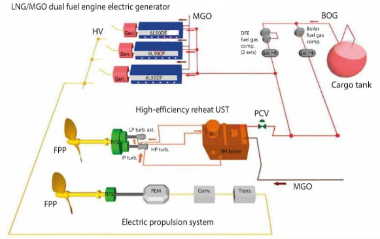
The STaGE plant achieves a higher reliability by combining proven technologies and high-redundancy by using different propulsion systems on the ship.
There are currently several STaGE ships on order.
COGES
What is COGES?
COGES is combined gas turbine electric and steam system.
Currently there are no gas turbine powered LNG ships in operation, although a Classification Society has been given approval in principle for a gas turbine powered LNG ship.
Gas turbines are not a cheap source of power and so the criteria for using them has tended to be where the particular characteristic of the gas turbine such as reduced weight (60 % lighter than conventional engines), high power density and compact size have been overriding considerations. The increasing costs of the installation and the higher running costs associated with meeting emission standards are narrowing the gap between the costs of low speed diesel installations and those of gas turbines and the reduced space requirements of the gas turbine and the flexibility in location may mean more space for cargo.
In an LNGC, the gas turbine would be installed in a COGES arrangement, with a secondary steam turbine incorporated into the system to gain extra power from an exhaust heat recovery system. The gas turbine will drive a generator that will power an electric propulsion motor, removing the requirement to have a gearbox to reduce the turbine rpm of 3 500 down to the requirements for an efficient low speed propeller. By using an electric drive system, a gas turbine/generator arrangement could be located anywhere in the ship, therefore further reducing the requirements for engine room space and increasing that for cargo. The steam generator component could supply power to the propulsion system, hotel load, ship service load and components requiring live steam.
To date, no estimate is available of the additional capital cost of installing a gas turbine compared with a diesel installation, but it is expected to be significantly higher.
Currently, gas turbines do not have a vast array of engine types with various power outputs like diesel engines, so their application is not as flexible and any installation would have to be aligned with the combined gas turbine electric propulsion packages proposed by manufacturers.
Two COGES options have been proposed:
- the first consists of one large gas turbine with, an associated heat recovery steam generator and steam turbo generator, with a small gas turbine generator as a standby. Due to the system redundancy in case of the main gas turbine failure and the need for blackout recovery capability, a conventional diesel generator would be fitted;
- the second option consists of two identical gas turbine generators associated with heat recovery steam systems, which provides more redundancy but would be a more expensive solution.
The system as shown below could provide the desired levels of safety, redundancy and operational back-up flexibility required by owners and charterers.
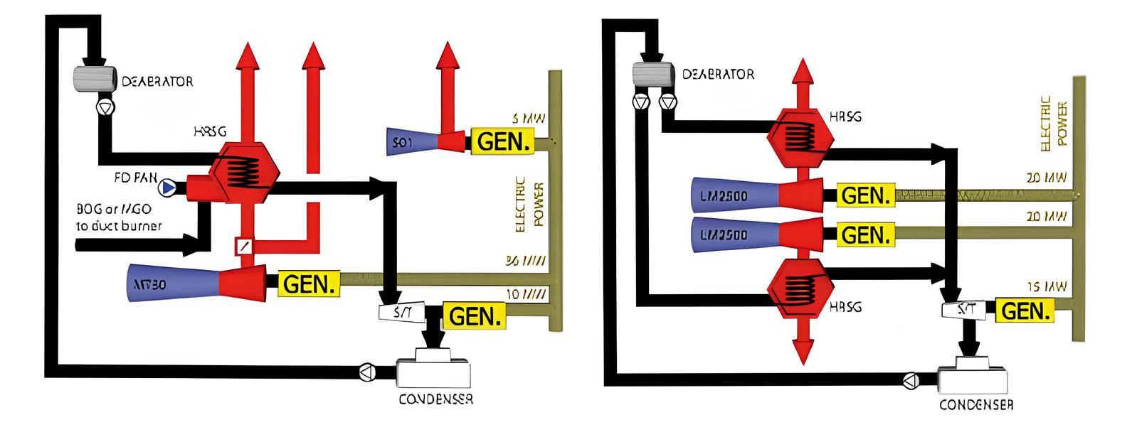
The gas fuel supply system is similar to that for other gas burning propulsion alternatives – the gas pressure is up to 40 bar depending on the type of gas turbine. The gas fuel line in the machinery space would be connected to the gas turbine package directly and constructed as a ventilated double-walled pipe, kept as short as possible to reduce the possibility of gas leakage into the safety area.
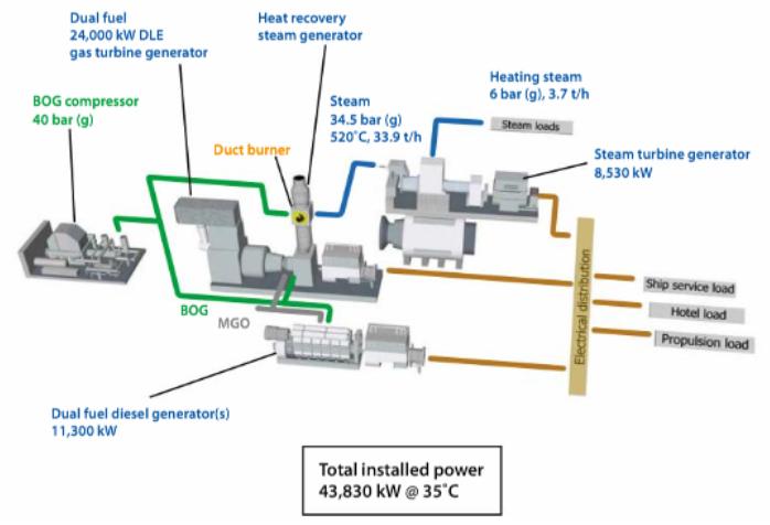
The gas turbine would be delivered as a:
- self-contained unit, e. g. gas turbine engine;
- gas valves;
- local fire extinguisher;
- gas detecting sensors;
- ventilation fans and dampers;
- interlocking device at container entrance door;
- control system, etc.
An electric starting motor or a separate hydraulic starting module is provided for gas turbine start-up and the lubrication system is also self-contained. A cooling water system is not required as cooling is provided by the air induced by the compressor section of the turbine.
The gas turbine can control and burn any ratio of gas fuel and fuel oil and the governor follows up rotating speed and controls the fuel amount injected into combustors.
| COGES Plant | |
|---|---|
| Advantages | Disadvantages |
| The option with the highest heat recovery efficiency | The fuel for aero-derivative gas turbines is relatively expensive compared to marine fuels |
| Maintenance is normally running hours based and the turbines can be removed from the ship for replacement, with limited maintenance requirements for ship’s staff | All gas turbines are less efficient as the ambient temperature rises and this is particularly true of aero-derivative turbines |
| Low weight/size gives flexibility when locating them in a ship and allows larger cargo carrying capacity for the same size of ship | Thermal efficiencies are lower than for diesel engines of similar power |
| NOx emissions are low and SOx emissions are negligible | Although the technology is available, no ship has yet been contracted with a COGES plant |
| BOG can be readily and effectively used as fuel | In the event of failure, certain maintenance, especially in the “hot parts” would not be possibly by ship’s staff |
| Gas turbines have very high reliability | Higher fuel gas pressure required (approx. 40 bar) compared to DFDE/TFDE option, imposing a greater electrical consumption |
| Relatively high power output variations, depending on ambient air temperature | |
The power turbine would be connected to the electric generator via reduction gearing. Hot exhaust gas from the turbine is led to the heat recovery steam generator, which generates superheated steam to power the steam turbo generator. When selecting a gas turbine for required power, their sensitivity to intake air temperature must be considered when locating and installing the unit.
Further considerations for LNGC propulsion systems
Redundancy is required by the International Association of Classification Societies (IACS) and, unless a CST or UST plant is fitted, one of the following options must be installed:
- thermal oxidizer GCU/flare system capable of burning the maximum BOG rate (to deal with the surplus gas in emergency cases);
- two 100 % reliquefaction plants with a common cold box.
On ships fitted with twin propellers, 50 % of the propulsion power will always be available and, depending on the configuration, some of the diesel engines can be maintained without immobilising the ship.
On 1 January 2020, the International Maritime Organization (IMO) regulations to reduce sulphur emissions to 0,5 % for global marine fuels came into effect.
There are three main methods to comply with the limit, which come with trade-offs between up-front capital costs and fuel costs.
- the simplest method to meet this emissions limit is to use a cleaner liquid fuel;
- a second compliance option is to install scrubbers that will remove the sulphur from the exhaust gases, since the standard is an emissions standard and not a fuels standard. The scrubber installation requires significant capital expense, but then shippers can continue to burn high-sulphur fuels;
- the third option is to power the ship with LNG. In most cases, this is the most capital-expensive option, requiring significant modifications if not a complete replacement of the ships engines, which makes it a more feasible option for new build rather than existing ships.
The currently dominant alternatives are ME-GI and X-DF propulsion systems.
Read also: M-type electronically controlled gas injection (ME-GI)
Diesel engines can operate for decades as all wear parts are replaceable and many examples of low operational life diesels are seen in shore power plants.
Provision and retention of enough well-educated crew members for the different propulsion systems is a major challenge for the market.
Despite the low efficiency of steam propulsion plants, LNGCs are expensive to build and many are tied to long-term contracts. As there are approximately 200 LNGCs in operation, the steam propulsion option will remain for the foreseeable future.
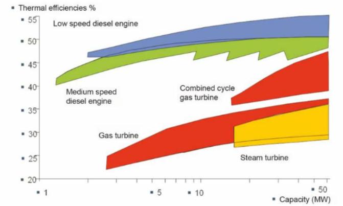
Figure 3.85 compares the different propulsion efficiencies, showing that 2-stroke diesel engine solutions are the most efficient (but only in the region of 50 % thermal efficiency).
Emissions
Steam dump – only applicable on steam powered LNG ships.
The boilers on a steam turbine ship (CST and UST) burn the BOG. Should the amount of BOG exceed that required for ships power requirements, the production of steam can be increased and the excess steam dumped to the main condenser or an auxiliary condenser, via the main dump de-superheater. The spray water for the de-superheater is provided from the main or atmospheric drain tank (ADT) condensate pump. The de-superheater can drain to the ADT, via the auxiliary condenser, if the main condenser is unavailable. The dump de-superheater outlet temperature is monitored and controlled by a spray water control valve.
Gas combustion unit. The gas combustion unit (GCU/thermal oxidiser) is used to burn excess BOG in a separate burner unit positioned in the ship’s funnel stack (see Liquefied Natural Gas Reliquefaction Plant“Gas Combustion Unit (Oxidiser)”).
Reliquefaction plant
Instead of using BOG as fuel, a reliquefaction system is a mechanical plant that has the ability to convert the BOG back into its liquid phase and returns the LNG to the cargo tanks.
Although several alternative refrigeration cycles can be adapted for this purpose, the most common utilises reverse brayton cycle, extracting heat from the BOG as it is less sensitive to feed gas concentrations. The gas composition is determined by where the cargo has been loaded as each LNG project has differing LNG compositions.
Reliquefaction plants have been installed on LNGCs for over a decade and relevant operational experience and maintenance requirements are well understood.
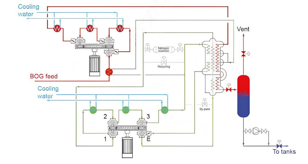
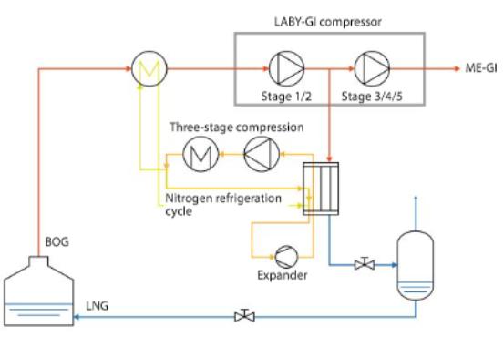
As an example, in the Wärtsilä Hamworthy system the BOG is removed from the cargo tanks by means of a two-stage centrifugal compressor. The BOG is cooled and condensed to LNG in a cryogenic heat exchanger (cold box). In the heat exchanger, the nitrogen refrigeration cycle takes heat from the BOG and turns it into a liquid. Non-condensables, mainly nitrogen, are removed in a separator vessel, resulting in a progressive removal of N2 from the cargo tanks during the voyage, reducing the power load on the reliquefaction plant. From the separator, the LNG is returned to the cargo tanks by the differential pressure in the system. The cryogenic temperature inside the cold box is produced by means of a nitrogen compression/expansion cycle. The BOG compressor capacity is adjusted automatically in accordance with the boil-off rate and the cargo tank pressure is kept almost constant by varying the mass flow through the compressor.
Increasing and decreasing the nitrogen filling is the basic control mechanism for the cooling capacity of the nitrogen cycle. Sensors and transmitters provide the required input signals to a programmable logic controller, which will be part of the main ship control system.
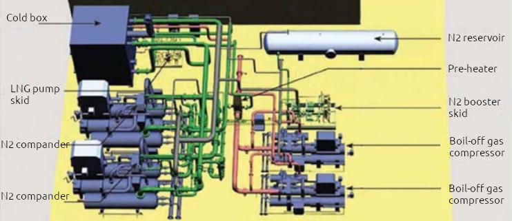
The main difference to the first generation reliquefaction systems is that the compressor unit has an additional compressor stage and inter-stage cooling. Heat is added to the BOG before it enters the main cooling circuit so that the heat of compression can be removed at high temperatures in the cooling arrangement. The additional compressor stage allows the process to condense the BOG at high pressure and temperature. This effect and that the heat of compression is removed early in the process are the main reasons the power consumption is reduced by some 15 %
Another example is the Burckhardt LABY-GI compressor system, which was developed to meet owners/operators requirements to provide reliquefaction capacity alongside the ability to supply fuel gas to DF diesel engines. It is used to pressurise the BOG and for pressurisation of the cooling medium, as well as to achieve the natural gas pressure of 300 bar needed for injection into a two-stroke engine system. This compressor incorporates all the compression functions required for the liquefaction system and the combustion system.
The LABY-GI Mark III system is designed as a combination system for liquefaction of Mark III and a DF propulsion two-stroke engine. The system for liquefaction differs in that the BOG compressors have been replaced by vertical reciprocating compressors. The compressor is a five-stage one, of which the first two stages are a part of the cargo liquefaction system (5-6 bar), and the other three raise the pressure to 300 bar for gas injection into the DF main engine.
The LABY-GI TGE system is intended for LNGCs of capacity between 170 000 cm3 and 210 000 cm3. It does not use nitrogen like the reverse Brayton cycle, but instead combination of propylene and ethylene in the cascade cycle. The compressor also supplies fuel gas to a combustion engine at a pressure of 150-300 bar.
| IACS Rules for BOG handling on SSD or DFDE/TFDE ships | |
|---|---|
| Option 1 | 2 × 100 % design BOG capacity reliquefaction units. Common cold box may be accepted |
| Option 2 | 1 × 100 % design BOG capacity reliquefaction unit and 1 × 100 % design BOG capacity GCU |
| Option 3 | 1 × 100 % design BOG capacity GCU with redundant fans, igniters, gas flow valves and combustion control systems, or |
| 2 × 100 % design BOG capacity GCU, or 3 × 50 % design BOG capacity independent GCUs | |
| Gas fired boilers or IG generators can be used as GCU | |
For liquefaction, in three stages of compression the pressure from the cargo tank rises to 45 bar and is condensed at minus 100 °C (-100 °C) within a double compression of ethylene by an intermediate cooler.
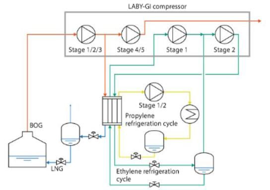
In the same heat exchanger, ethylene is condensed at minus 30 °C (-30 °C) and 19 bar by transferring the heat to the propylene cycle. The condensation of propylene at 17 bar and +40 °C takes place in a closed cascade cycle, with two degrees of compression by a separate screw compressor.
