This article examines applications of Compressed Natural Gas (CNG) carriers, using event-domain simulations to assess transportation system operating efficiency. This new gas transport system requires very limited investment in infrastructure dedicated to a specific field.
As confirmed in a recent study for a leading US energy company, it is even possible that gas wells for certain reservoirs can flow directly onto the ship and into storage without any significant in-field investment beyond traditional subsea tie-back facilities.
Summary
That study investigated the feasibility of developing an ultra-deep water gas field by producing directly from subsea wells into a pair of Gas Production/Storage Shuttles (GPSS™) that alternate between producing and transporting duties. These shuttles are designed using EnerSea Transport’s patented technology for volume-optimized transport and storage of CNG (VOTRANS™).
CNG marine transport allows emerging, energy-hungry markets around the globe to access gas reserves that would otherwise continue to remain stranded. The scalable CNG solution may also help energy operators to globally reduce the amount of energy being flared or wasted. As compared to other solutions for de-stranding of gas reserves (LNG & GTL technologies), the shipping of CNG offers a solution that significantly limits the wastage of gas resources that are needed in the emerging markets and the amount of captive investment required of operators.
Introduction
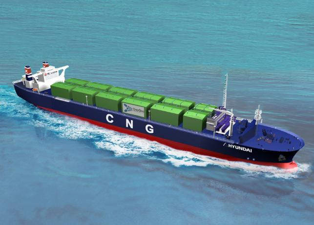
The natural gas maritime transport industry has prospered recently, building momentum upon the successful track record of LNG and LPG carriers, and the upsurge in global demand for clean energy. This paper introduces a marine gas transport technology under development by EnerSea Transport LLC and its partners as it is being incorporated in new ship designs. The new gas transport system and ship designs have global applicability and improve the prospects for remote offshore oil and gas development. The paper explains how key considerations and challenges have been reflected in the designs and how this new gas ship concept opens a new world of maritime and offshore field development opportunities.
This new gas transport system requires very limited investment in infrastructure dedicated to a specific field. It is even possible that gas wells for certain reservoirs can flow directly onto the ship and into storage without any significant additional in-field investment. A recent study for a major US energy company has investigated the feasibility of developing an ultra-deep water gas field by producing directly from subsea wells into Compressed Natural Gas (CNG) Carrier ships. Production interruptions may be avoided as two Gas Production Storage Shuttle (GPSS) vessels storing CNG switch roles between producing/storing via one of two Submerged Turret Production (STP™) buoys and transport CNG to an offshore offloading terminal located near the market.
CNG marine transport allows emerging, energy-hungry markets around the globe to access gas reserves that would otherwise continue to remain stranded. As compared to other solutions for de-stranding of gas reserves (e. g. LNG & GTL technologies), the shipping of CNG offers a solution that can make available gas resources that are needed in the emerging markets while reducing the amount of fixed-asset investment required of operators and the amount of gas lost in other gas disposal options. Such value-adding features make this breakthrough technology and the new class of ships attractive to gas and power players on a global scale. Analyses of operating availability (or “regularity”) using the advanced event-domain simulation software, SLOOP, demonstrate the effectiveness of production and transport scenarios described in the paper. Such analyses are the backbone of commercial assessments that establish the attractiveness of the stranded gas solutions introduced in this article.
Volume-Optimized Natural Gas Transport Technology (VOTRANS™)
Natural gas is a complex fluid that exhibits non-ideal gas properties when compressed above 70 bar (1 000 psi). The non-ideal characteristics can be accommodated by adjusting the “Ideal Gas Law” through the introduction of what is commonly called the compressibility factor (or “Z-factor”). The gas industry has generated much documentation and many calculation models to estimate/predict the Z-factor effects in gas compression engineering. EnerSea’s Volume-Optimized TRANsport and Storage (VOTRANS™) technology has recognized the relationship between the weight of containment systems and the Z-factor effect in gas storage design. By chilling gas to a suitably low temperature (usually well below 0 °C), it is possible to compress great quantities of gas into long tubular containers such that the ratio of the weight of the gas stored to the weight of the container is optimized. The cost of compression and the cost of the containers (and, therefore, the ships) can be greatly reduced by storing cold gas at relatively moderate pressures. These savings are somewhat offset by costs for refrigeration and insulation, but operational considerations and the sensitivity of cost effective ship design to the weight of CNG containers clearly reveals the value of lighter steel pipe containers.
EnerSea’s VOTRANS systems also employ a means for efficiently handling the transfer of cargos into and from the Cargo Containment Systems of LPG and LNGcargo tanks. A patented liquid displacement system provides the means to control pressure and temperature of the gas throughout the processes. By controlling back-pressure when loading gas into containers, temperature extremes due to auto-refrigeration and heat of compression effects can be avoided. Using the displacement fluid as a piston to push the gas cargo out of the containers at the discharge terminal prevents drop-out of natural gas liquids.
An important feature of EnerSea’s technology is that the volume-optimization approach allows substantial transport system design and cost efficiency advantages when “richer” gas streams are involved (such as would be the case for gas associated with oil field production). The low temperature compressibility characteristics of “rich gas” mean that more cargo can be stored at lower pressure (in lighter, less expensive containers) than “lean gas” cargos. Due to the high energy content of “rich gas”, the economics of associated gas transport can be extremely attractive for transport distances less than 3 000 nm.
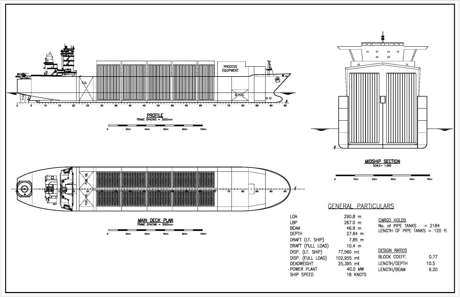
VOTRANS™ principles work well and generally apply to tubular containers of any material. However, due to the relative cost and proven reliability of steel pipe containers, the first generations of CNG ships will carry large diameter, high strength steel pipe tanks. EnerSea Transport has investigated many alternatives to high strength steel and has found them, especially pure composite tanks, to be uneconomic. Vertically oriented steel “pipe tank” bottles are incorporated within chilled, inerted and insulated cargo holds for the current ship designs (Picture 1).
Gas Cargo Handling and Storage
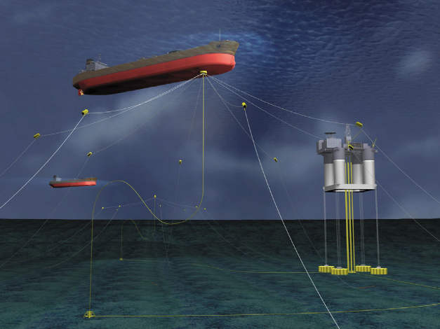
To limit the amount of time at the loading and unloading terminals, VOTRANS ships can be configured to include dynamic positioning systems for connection to an efficient bow loading system or internal turret device similar to the Advanced Production Loading A/S (APL) shuttling loading system installed at Norway’s Heidrun field, Picture 2.
Generally, shipboard gas handling system design assumes the gas arrives on board at a pressure that allows the gas to be injected into the storage containers at lower temperatures and pressures according to the described volume-optimization principles.
Loading is expected to take place at a rate corresponding to the production rate of the field being serviced such that the cargo containers are usually filled in 2-3 days. The delivery pressure from the in-field facilities determines how much pressure reduction and chilling is required on the ship. Fields producing dry gas at relatively high pressure to the CNG ship provide the opportunity to use the auto-refrigeration phenomenon of gas expansion to limit chiller duty onboard. In the current design, it is assumed that the gas is supplied at moderate pressures and temperatures, so refrigeration equipment is required on board ship.
At the gas delivery terminal, it is also desired to limit turnaround time. Therefore, the ship is provided with a liquid displacement system that ejects the cargo from storage in an efficient and controlled manner. Once the CNG ship is properly connected to the delivery terminal, gas is discharged through the internal turret to a flowline that ties into a subsea pipeline connection. Pumping capacity is usually designed to discharge the cargo within 24 hours. The displacement liquid is kept chilled and carried in insulated tanks forward with enough capacity to support a cascading displacement operation.
Shipboard gas handling facilities also include relief and venting systems appropriate to the upset and emergency conditions projected for the gas transport scenarios. Hazard management studies have investigated suitable responses for gas release scenarios.
A Container Design
The gas bottles (or pipe tanks) are fabricated from high strength steel pipes with end caps and nozzles produced for the specific project requirements. The bodies will be made from two 12 m (40 ft) or 18 m (60 ft) large diameter pipe joints. The end caps (or heads) are formed with a protruding nozzle from a suitable high strength plate material. The pipes and heads must be made from high strength materials that maintain low temperature toughness in the as-welded condition. Current designs are based on specially developed API 5L X80 pipes at least 1 m (typ. 42 in) in diameter. However, future designs are likely to employ even higher strength materials with diameters exceeding 1,2 m.
The gas bottles are considered to be pressure vessels and are generally designed to meet ASME Section 8 Div 3 under special Code Case considerations for the intended service. The US Coast Guard is expected to require ASME compliance for operations in US waters, but both Det Norske Veritas (DNV) and the American Bureau of Shipping (ABS) have developed guidelines that will allow rational/probabilistic design methods to demonstrate suitability for marine service and class. In any case, design pressure, bottle diameter, and material strength are the primary determinants of wall thickness and weight of the individual bottles.
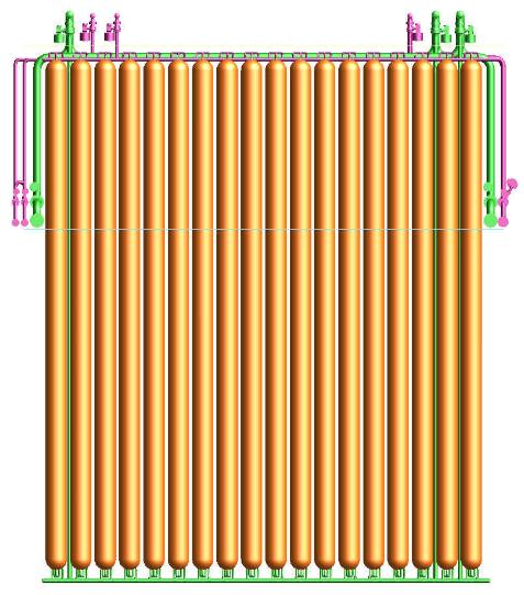
The individual bottles can be placed into the insulated holds individually during ship construction to be connected to top/bottom manifolds to create manifold groups in the holds. Isolation valves on manifold groups (comprised of as many as 36 bottles) form the basis for cargo segregation while in transit. Individual bottle installation leads to a manifold arrangement where pairs of transverse rows of bottles form a manifold grouping (Picture 3).
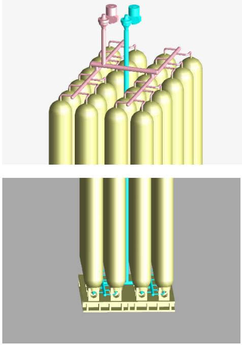
Alternatively, it is possible to arrange manifold groups into modular units with rigid skid bases that allow remote module fabrication and a reduced number of heavy lift operations (Picture 4).
A number of manifold groups (usually 3 to 6) can be interconnected through valve arrangements to create a loading (or unloading) “tier”. A loading tier may consist of as many as 164 bottles. The amount of displacement liquid to be carried on board ship is dependent on the internal volume of a tier (usually about 1,5 × tier volume).
Ship Design and Development Status
A Design Evolution
A discussion of key design “drivers” or constraints can illustrate the evolution of the current VOTRANS CNG Carrier designs. Key drivers are:
- Regulatory and class requirements;
- Mission requirements (gas cargo characteristics and required storage capacity);
- Construction and commissioning considerations;
- Operability.
Due to the immature status of this emerging industry, many potential beneficiaries worry unduly about the ability of a marine CNG transport project to gain regulatory approval. Much of this angst was resolved by the success of the 1st International Marine CNG Standards Forum held recently at Memorial University of Newfoundland, under the sponsorship of The Centre for Marine CNG. This event gathered together a truly international delegation comprised of many CNG competitors, energy companies, shipping companies, leading professional organizations (SIGTTO and ASME) and class societies, as well as key maritime administrations and representatives from other governmental oversight agencies. The official communiqué of the Forum noted that the state of guidance for classification and regulatory purposes is well advanced, and that alignment across the industry was a practical goal. The Forum leadership also recognized that the CMCNG was positioned to play an important role in advancing the state of the technology toward practical standards and implementation.
The International Gas Carrier (IGC) Code provides the foundation for establishing a pathway to regulatory approval. However, due to the fact that the IGC Code did not adequately anticipate large scale marine CNG transportation projects, both ABS and DNV have prepared guidelines (or “Rules”) to more fully address the critical features of safety review for classification. A “safety case” approach, involving intense Flammability, Explosion and other Hazards of Liquefied Gashazard identification and mitigation exercises, as well as quantitative risk assessments, complement the codes and guidelines to ensure safe designs as well as operating practices.
Having completed the initial complement of hazard identification and operability studies, the overarching consensus of the reviewers is that CNG fleets can meet, and possibly exceed, the level of safety established by the maritime LNG industry.
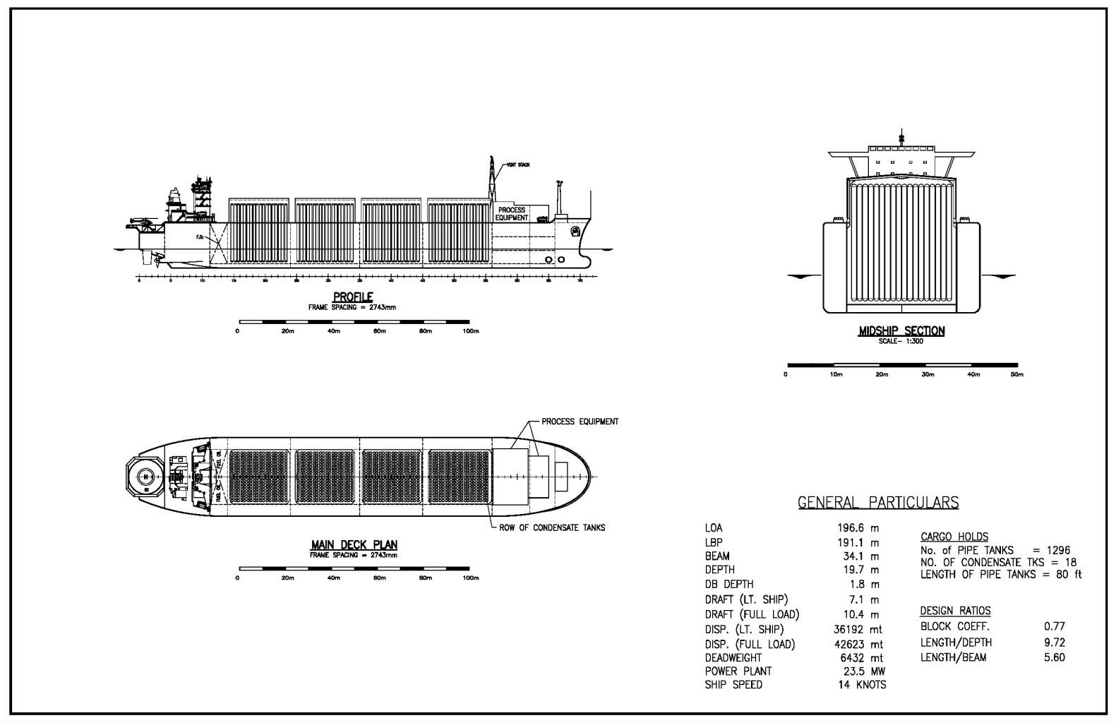
The most obvious regulatory consideration impacting the hull design is the concept of a “double barrier”. A reasonable interpretation of the IGC Code tends to push designers toward a double hull configuration shown in the general arrangements presented in this article. Due to the relatively high weight of CNG containment systems, the wing spaces tend to be very wide – greatly reducing the likelihood of the cargo holds being breached in case of collision.
Inspection (and maintenance) considerations drive the dimensioning of and arrangements within the holds. Accessibility requirements are well recorded in existing Rules for Marine Vessels. Since the perimeters of VOTRANS ship holds are insulated, additional clearance must be provided around tanks near bulkheads. In the VOTRANS system design approach, periodic visual inspection of cargo tanks (the “bottles”) and associated piping is supplemented with a continuous integrity monitoring system based on Acoustic Emissions (AE). All manifolds are instrumented with AE sensors such that critical areas of all tanks can be monitored throughout the service life. If critically developing indications are recorded, individual bottles or manifold groups can be temporarily or permanently decommissioned. Due to the high degree of segregation and low probability of failure, there is currently no intention to remove, replace, or repair any individual bottles.
Forward visibility standards have been established to ensure navigational safety. Even though the cargo tanks and hatch covers are relatively tall, it will still be operator’s choice regarding aft or forward helm location. Adequate navigational visibility can be achieved with helm aft, as found for Moss type LNG carriers and modern super-sized container ships, without requiring extraordinary superstructure heights.
Mission requirements clearly provide a competitive edge for EnerSea’s VOTRANS, as this technology allows for a great deal of optimization relative to the design of facilities and a fleet dedicated to a specific project. In the early decades of this new maritime industry, it is anticipated that the CNG Carriers will be committed and built for long-term service contracts. Such a market-driven situation emphasizes the importance of designing and optimizing the ships in a fleet for that initial commitment contract and enhances the advantage of volume-optimization design principles.
Market opportunity reviews have led EnerSea to focus on designs in a cargo capacity range of 15-30E6scm (approx. 500-1 000 mmscf). Although VOTRANS technology may be applied for either horizontal or vertical “pipe tank” configurations, EnerSea has determined that vertically oriented tanks are appropriate for the prime target range of cargo capacities.
The VOTRANS systems are capable of transporting a very wide range of gas compositions and supply conditions with limited gas handling facilities installed on the CNG carriers. When a dry, sweet gas stream is supplied at a pressure adequate to charge the containment system (approximately 90 bar for “rich” streams up to 125 bar for “leaner” gas when storing the gas at -30 °C), onboard gas handling facilities are minimal.
Construction and commissioning require early consideration when generating both the ship design and the project management plan. CNG carriers represent a new class of vessels that will challenge the capabilities of traditional shipyards. Only the most capable, progressive shipyards will be prepared to undertake the complete project to deliver a fleet of CNG carriers. In any case, if the containment system is too heavy (or the hull lines are too fine), the ship cannot be completed in drydock. As an alternative gas cargo systems may best be fabricated, installed, and commissioned at a specialized fabrication facility. Therefore, alternative construction scenarios have also evolved that may not wholly depend on a single shipyard.
EnerSea’s VOTRANS CNG Carriers have been designed such that they can be completed in drydock because the containers are so light that the lightship weight can allow float out with all equipment onboard.
Operability targets are in many ways the most complex to address in achieving a practical implementation of a significant new technology. The overall ship dimensions were driven by a need to maintain and repair it over its entire service life. Maximum available draft at repair facilities around the world constrained the draft in the repair condition (basically lightship). The maximum lightship draft is, therefore, targeted to be substantially less than 8 m, based on a worldwide survey of all major repair shipyards. The effect of this constraint is to drive the overall length and beam with an associated reasonable block coefficient to arrive at a lightship displacement within the draft limits that can be accommodated at multiple repair facilities worldwide.
Ship speed and hence installed power are driven by many factors including gas production rate, distance to market, economical ship’s speed and fleet size.
The power required for propulsion sets the minimum size of the power plant. However, after initial cargo system design efforts, it became apparent that, in most cases, a large quantity of power is also required for cargo handling. This set the stage for an all-electric ship rather than a low speed diesel with a separate electric power generation system. A twin-screw arrangement was chosen, in part because of the small change in draft between light ship and full load, and also to provide for additional overall vessel system redundancy.
The choice of prime mover and type of fuel was set after discussions with ship operators regarding availability of ship’s engineers trained in the operation of gas turbines versus heavy fuel oil diesels. Dual fuel diesels (gas and heavy fuel oil) can be considered but, due to the CNG cargo system’s inherent capabilities, gas boil-off will not occur. Thus, to maximize delivery of the gas, heavy fuel oil prime movers are normally selected. For projects where re-fuelling and fuel availability are primary concerns, then the dual-fuel option deserves serious consideration.
A high degree of cargo system monitoring and automation has been incorporated into the design to minimize the size of the crew. Limited additional crew training will be required to ensure safe operation of the cargo loading and offloading systems. Most of these systems are extensions of existing marine systems though maybe somewhat larger, such as the cargo cooling system.
B CNG Carrier Development Status
ABS granted “Approval in Principle” to EnerSea for the design and operating plans for a generic V-800 VOTRANS ship in April 2003. The V-800 ships are notionally designed to carry up to 22,7E6scm (800 mmscf) of rich gas. The ship design concepts being subsequently considered for new project-specific opportunities are taking onboard the lessons learned from that design exercise and the interactions with the knowledgeable review team at ABS.
EnerSea has ensured that design and technology development is in line with commercial project development status. Front-end activities for a number of CNG project application opportunities are underway in 2004. Announced early phase project studies include Unocal’s Indonesia-Philippines “open season”, Oil Search Ltd’s Papua New Guinea-New Zealand venture, and Husky Energy’s White Rose gas development. In addition to advancing a number of confidential investigations, EnerSea’s project teams are working diligently to nurture one or more of these publicly announced opportunities to project sanction within the next 12-18 months.
In the meantime, a multi-million dollar technology validation program is moving into the final phases with participatory commitments and funding from clients and key suppliers. This validation program features both a functional testing program with the Gas Technology Institute, and a full scale cold temperature fatigue and burst test program. Additional special topic studies and analyses are complementing the main technical objectives with investigations into fracture/fatigue toughness and cold jet gas release thermodynamics. These strategic investigations combine to support decision-making hurdles with key clients and timely development of the foundations for an ASME Code Case application.
Gas Production/Storage Shuttling System Concept
In addition to the early phase project-specific studies noted above, EnerSea has joined with Kerr-McGee Corporation to lead a feasibility study of an innovative ultra-deepwater field development concept. This work involved a large multi-discipline team in a eight-month effort co-funded by the Research Partnership to Secure Energy for America (RPSEA).
As industry continues to push the frontier boundaries of ultra-deep water and remote location finds, EnerSea Transport LLC has addressed the challenge by taking its VOTRANS™ compressed natural gas (CNG) carrier and expanding it into an all-in-one deepwater gas production and transport vessel called the “Gas Production Storage Shuttle”.
This shuttling concept (Picture 5) offers energy companies the ability to eliminate much of the infrastructure traditionally required for remote gas field development, such as expensive ultra-deepwater pipelines, and dedicated production facilities. While aggressive infrastructure expansion and US cabotage requirements challenge deployment in the Gulf of Mexico, international case study cost analyses have shown savings of at least 20 % in capital costs for field production operations support, storage and transportation for a deepwater gas field development may be achieved across a broad range of applications by employing the GPSS concept.
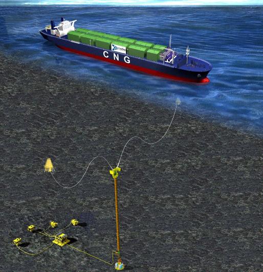
The GPSS is analogous to an FPSO used in oil service with the added capability of transporting its gas product to market. It combines all of the features and advantages of the VOTRANS CNG carrier, including proprietary gas containment and gas handling technologies, with direct operational control and support for the subsea gas field and processing systems for the produced fluid onboard (Picture 6). The shuttle vessel concept also serves as a storage facility for gas and liquids and, when filled to capacity, disconnects from its production buoy/mooring to deliver the gas to market. Use of a pair of Submerged Turret Production (STP™) buoys from APL and multiple vessels operating in a shuttling fashion allows for uninterrupted production from remote fields.
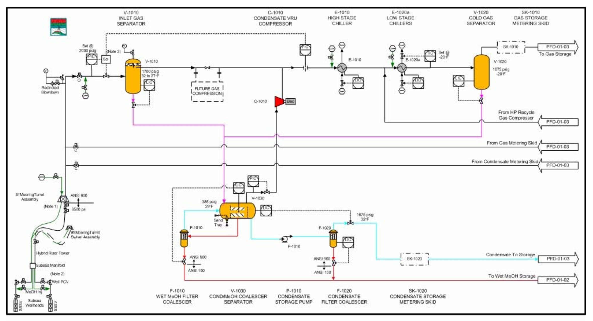
Throughout early field life, reservoir energy provides the motive drive to push the lean gas fluids through the gas handling facilities and into the shipboard storage. The process facilities include features for methanol injection and recovery to support the subsea production scenario and avoid hydrate formation problems (Picture 7). As pressure declines, the GPSS has been designed to allow installation of a compression module to continue reservoir evacuation and extend the economic field life.
The study concludes that the novel GPSS system is technically feasible as a production and transportation solution for remote or deepwater gas field developments. Economic case studies have determined that transport and production services for such a development scenario could be provided under a commercially competitive all-inclusive tariff over a long-term contract based on production rates as low as 2E6scm per day.
Operational Simulation
Computer simulations of oil transportation have been used for many years to help optimise shipping capacity, cargo storage and terminal facilities. BMT Fluid Mechanics Limited (BMT) originally developed the SLOOP software in 1995. It was then substantially enhanced as a result of a Joint Industry Project funded by 9 oil majors. Since then, it has been used on a very wide range of offshore field development and transportation projects (e. g.).
Read also: Ship/Shore Interface in Gas trading
What sets the SLOOP simulation model apart from the majority of transportation simulations is its ability to model the whole hydrocarbon trade “from wells to market”. This enables a complete picture of the operation of an offshore field (with drilling operations, subsea intervention, process maintenance etc.) to be fully integrated with the product export (shuttle tankers, storage facilities, pipelines etc.). The simulated operations can all be made dependent on weather/metocean conditions, and this can be of particular importance where the field is located in a severe marine environment.
Simulations of this type have a particular role to play in ensuring that the loading and transportation technology being used is appropriate to the metocean conditions. Investment in expensive high performance systems needs to be justified with evidence of the return (additional oil/gas delivered, and hence revenue generated). SLOOP provides this evidence, enables feasibility to be demonstrated, and helps to drive optimisation of the overall field/export/market system.
It is not just the offshore weather that can influence operations. The performance of various on-land elements of the supply/delivery system, such as at-field or at-market hydrocarbon processes (e. g. LNG liquefaction plant) can be dependent on weather effects such as ambient temperature. SLOOP has a very powerful and general capability to take in weather climate data, and use this data to influence operations in a realistic manner.
In some cases it will also be important to model the The State of Global Liquefied Petroleum Gas Market in XXI Centuryinfluence the market has on the hydrocarbon production and transportation. Gas is often delivered to customers who have onerous energy transmission obligations. There may also be seasonal variations in the market. A failure to operate at the required level of delivery regularity may result in financial penalties, which might have a significant impact on the economics of the whole operation. Consequently SLOOP has the ability to include contractual delivery obligations, and to track the performance of the field/export system in meeting these obligations.
Investigation of System Operating Efficiency
Case studies have been developed for scenarios notionally representing two important regions for international CNG opportunities. The selected cases represent two very different stranded gas scenarios.
Case-A: a North Atlantic field with a severe metocean environment exporting gas to the Eastern seaboard of the US. Key features of the scenario are:
- Field Location: North Atlantic exposed location;
- Production: 5,67E6scm/d (200 mmscf/d);
- Field gas storage: none;
- Export technology: 2 × submerged turret loading buoys;
- CNG carriers: 3 × 19,8E6scm (700 mmscf) capacity, 18 knot speed;
- Delivery port location: US Northeast coast (exposed unloading terminal location);
- Route length: 1 000 nm (nominal 55 hr one-way transit time, but with random delays of up to 33 hrs due to ice for three months of the year).
Case-B: a relatively benign deepwater location in SE. Asian waters with export to the Philippines. Key features of the scenario are:
- Field Location: Offshore SE Asia;
- Production: 5,67E6scm/d (200 mmscf/d);
- Field gas storage: Barge with 9,9E6scm (350 mmscf);
- Export technology: Over the bow loading from either of 2 barge corners;
- CNG carriers: 3 × 14,7E6scm (520 mmscf) capacity, 18 knot speed;
- Delivery port location: Manila Bay;
- Route length: 1 000 nm (nominal 55 hr one-way transit time).
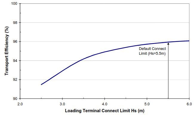
The overall average production efficiency of the Case-A base case is predicted at 96 % (gas delivered to destination port/nominal field gas production). This includes the disruption for dry-docking each of the carriers for 30 days every 5 years, and some quite onerous random delays due to the effects of ice during 3 months of the iceberg season (especially the “growlers” and “bergy bits”). The submerged turret loading technology assumed for the dynamically-positioned (DP) CNG shuttle vessel is an important component of the system.
The simulations assumed that it would be possible to connect the shuttle to the buoy in up to Hs = 5,5 m, and could remain connected in up to Hs = 10 m. This sounds extreme, but is understood to be similar to operating limits being currently achieved for oil shuttling operations from the Heidrun field in the North Sea using similar loading technology. Using more conventional over-the-bow loading technology would drop the overall system efficiency by about 4 % (reducing gas sales revenue by about $15 M per year at current US market prices). Picture 8 shows the effect of varying just the STL connect limit on the overall system efficiency.
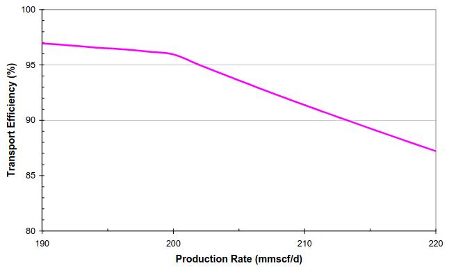
Picture 9 illustrates the extent of any spare capacity in Case-A. It can be seen that the efficiency of the system drops off quite rapidly if production is increased above 5,67E6scm/d (200 mmscf/d), demonstrating that the three 19,8E6scm (700 mmscf) CNG carriers are well matched to that production level.
Picture 10 shows the main elements that make up the 4 % of lost transport efficiency for base Case-A.
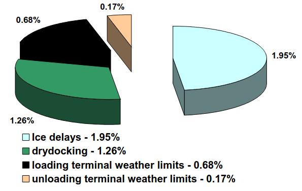
It can be seen that the high performance STL technology is very effective in keeping weather delays to a minimum, with just 0,68 % and 0,17 % being lost at the loading and unloading terminals respectively. The main remaining downtime components relate to the dry-docking of the ships, and delays due to transits in ice conditions. Case-B has the same production rate, and the nominally same delivery distance, but owing to the presence of field gas storage, and the much more benign environment of the field, and the delivery inside Manila Bay, an average production efficiency of over 98 % is achieved with three smaller CNG carriers (Picture 11).
This case includes the same dry-docking disruption as Case-A, while operational disruptions due to typhoon warnings are also included. The particular loading/unloading technology is much less important to this scenario as can be seen in Picture 12.
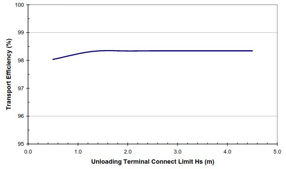
Although the combination of DP CNG carriers and over- the-bow loading from the barge is probably capable of connection in up to around Hs = 4,5 m, it can be seen that operating limits down as low as 1,5 m have little or no effect on the overall efficiency.
It can also be seen from Picture 13 that it is probably not necessary to have the full 9,9E6scm (350 mmscf) field gas storage with the 3 × 14,7E6scm (520 mmscf) CNG carriers.
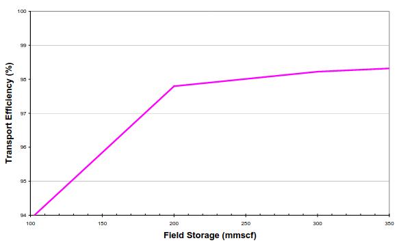
An economic analysis of the barge capital cost and revenue would be needed to determine an optimum storage, but the suggestion here is that around 5,7E6scm (200 mmscf) might be sufficient.
Cases A and B both demonstrate excellent operational efficiency. In the years when ships are not dry-docking, transport efficiencies for Cases A and B are 97,2 % and 99,7 % respectively, comparing very favourably with pipeline operations. Further simulations using SLOOP would probably identify operational refinements and additional performance improvements.
Conclusions
Large-scale marine transport of CNG is now imminent as confirmed by the announcements of a number of early stage project engineering initiatives. This article has documented advancements on many fronts – technology, regulatory (standardization), and project opportunities – that are bringing the new industry to realization within this decade.
The innovative features and concepts (e. g. the GPSS scenario), as well as the progress described, demonstrate how the advantages of EnerSea’s proprietary, volume-optimized CNG transport technology and acceptance of the transport service model being offered may be seen to establish a leading position in this important “step change” for the maritime industry.
Case studies using sensitivity analyses with the SLOOP event-domain simulation package clearly indicate that highly reliable fleet operations can be established (with availability/regularity that will rival pipeline operations) – even in the harsh environment offshore Atlantic Canada. The high likelihood that maritime administrations will be able to approve CNG transport, and the ability of CNG fleets to realize high transport efficiencies in operation, must be recognized as the industry moves into critical stages of acceptance and project/financial commitment.