Explore the efficiency and reliability of DFDE (Dual-Fuel Diesel Electric Engine) and TFDE (Tri-Fuel Diesel Electric Engine) medium-speed engines on LNG carriers. Learn how these cutting-edge propulsion systems optimize fuel consumption and environmental impact while ensuring smooth operations at sea.
These systems are equipped with an electric propulsion system that is powered by dual-fuel/tri-fuel, medium-speed diesel engines. In gas mode, they run on low pressure BOG, with a minimal amount of diesel used as a liquid spark (pilot fuel). Electric propulsion systems allow the prime movers to be located away from the propeller shaft into areas where there is more space and by having only the propulsion motors and the reduction gearbox on the tank top, the engine room can be substantially shortened.
Although maintenance on electrical motors is minimal, the higher maintenance requirements of the diesel generators must be taken into consideration.
The first LNGC to be powered by a DFDE propulsion system was ordered in 2001.
Shortly after the adoption of DFDE systems, TFDE ships offered a further improvement to operating flexibility with the ability to optimise efficiency at various speeds. TFDE ships have the ability to burn HFO, diesel oil and gas. The DFDE and TFDE plants differ only in the requirement to facilitate the provision of HFO to the engines, such as:
- loading facilities;
- storage tanks;
- heating;
- purification;
- pipework, etc.
DF engines can burn both diesel oil and BOG and TF engines can burn DO, HFO and BOG, working on the same principles as regular medium speed engines when operating on liquid fuels. Both options can improve the ship’s efficiency by around 25-30 % overt raditional steam turbines.
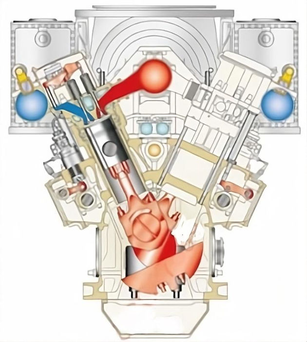
When running on gas, the engine runs in the “lean burn” mode according to the Otto cycle, where the lean air fuel mixture is fed to the cylinders during the suction. BOG from the cargo tanks is used as the fuel and is compressed to approx. 5 bar at the inlet to the engine.
A gas valve, controlled by the engine control system, is located at each cylinder air inlet pipe and opens during the piston suction stroke, ensuring the correct gas/air mixture is obtained for the operating load and combustion.
The gas mixes with the air in the cylinder head inlet air channel during the suction stroke and this mixture is compressed during the compression stroke. A small amount of DO is then injected in the form of pilot fuel (approx. 1 % of nominal fuel energy input) and this ignites the gas/air mixture.
The pilot fuel injector is located in the main fuel injector, but is separate from the main liquid fuel system, and a “knock” sensor is fitted on each cylinder. The timing of the pilot fuel injection is adjusted as necessary to eliminate knocking.
Natural gas has a low ignition quality and requires a high temperature to cause ignition. This allows the gas/air mixture to be compressed but means a pilot flame is then required to ignite the mixture.
When running in DO or HFO mode, the engine works according to the normal diesel cycle where the diesel fuel is fed to the cylinders at the end of the compression stroke. In liquid mode, no BOG is mixed with the liquid fuel.
The Diesel cycle differs from the Otto cycle by using a higher compression to ignite the fuel, rather than using a pilot fuel.
When DF/TF engines are running in liquid mode, pilot fuel is still injected to prevent pilot nozzle orifices from clogging.
To achieve the required accurate combustion control, the gas admission and ignition of cylinder charge are electronically controlled on a DF/TF engine.
Each cylinder is equipped with:
- electronically controlled valves;
- one gas admission valve per cylinder for gas injection into the air intake channel;
- one pilot injection valve per cylinder for the ignition;
- control of injection by the engine control system.
The DF/TF engine is designed to have the same output, regardless of the fuel used.
Each owner/operator will have their preferred installation footprint. A common choice is to have a total of four DF/TF engines, two separate DF/TF engine compartments and two engines installed in each compartment. The engine compartments will have separate gas fuel supply lines branched from the main line on the deck, providing further redundancy.
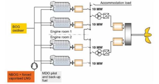
The diesel engines drive electrical generators that provide electrical power for propulsion, engine room equipment, auxiliary machinery and hotel services throughout the ship. The electrical power load will determine the number of engines in operation and the PMS will control the starting and stopping of engines to ensure the efficient operation of the generating plant under all circumstances.
Classification Societies require that switching between fuel options must take place seamlessly and without loss of power or speed.
Although BOG is essentially a good fuel for burning in diesel engines, its composition can cause concern. The main consideration is the % nitrogen that reduces the energy content of the gas when compared to pure methane. The nitrogen content in the BOG after loading (depending on the loading terminal) can be as high as 30 % and, although the engine and fuel control systems are designed to accommodate this condition, some initial de-rating may be required.
The BOG for these engines is normally provided via a mist separator, which removes the heavy components of BOG or any entrapped liquid that would result in damage to the compressor. The BOG is then fed via an Low Duty Compressor(s) on the Liquefied Natural Gas CarriersLD compressor located in the cargo machinery room, passing through a gas regulating unit (filter, pressure regulator, shut-off valve, ventilation valves, etc.) and, finally, into a common manifold with branches to each cylinder.
Gas entry to each cylinder is controlled and regulated by a gas admission valve (GAV) fitted to the cylinder head, ensuring ignition and good combustion.
Each engine is fitted with a “waste gate” facility that can divert some of the exhaust gas around the turbo-charger turbine, ensuring the global air-fuel ratio has the correct value whatever the ambient conditions, dividing the load between cylinders and ensuring there is no “knocking” in any cylinder.
The control and automation systems include the following safety functions:
- before starting, the engine is automatically ventilated by rotating without fuel injection;
- the engine is always started using fuel oil, even when gas mode is selected;
- during the engine start sequence, and before activating gas admission to the engine, an automatic combustion check is performed to ensure the pilot fuel injection system is fully operational;
- during gas firing, the combustion in all cylinders is continually monitored and, should a problem be detected, the engine will automatically revert to liquid fuel (diesel) mode;
- BOG may enter the exhaust system when a malfunction occurs during gas operation and could be ignited if a source of ignition is present. Therefore, the exhaust line of each generator is equipped with a ventilation system, operated by the engine control system, to ensure the exhaust system is ventilated for a pre-determined period after an engine has been stopped in gas mode;
- bursting discs are fitted in the exhaust lines below the heat recovery boilers to limit over-pressure in the exhaust system.
The areas around bursting discs are hazardous as they can operate without warning.
The electric propulsion system’s components will be familiar to most engineers on board. However, as the equipment is larger and the voltage is higher, there is a requirement for high voltage safety training as a prerequisite for operation and maintenance of these systems. Training will be required for new technology, such as the frequency converters that control the speed of the electric motors.
The manufacturers will offer specific training courses on the operation and maintenance requirements of the different elements of the Exploring Propulsion Systems and Turbo Alternators on Liquefied Gas Carrierspropulsion system.
To allow gas burning, two parameters must be regulated:
- the pressure within the cargo tanks must be kept within the acceptable operating range;
- the pressure delivered to the engines must be approx. 5 bar.
If the gas demand is higher than the natural BOG rate, additional fuel gas or “forced BOG” (FBOG) is required. It is produced by pumping LNG from the cargo tanks to the forcing vaporiser and the resulting FBOG is led through a mist separator and a buffer tank to the gas heater, where it mixes with the NBOG from the LD compressor.
Read also: Dual-Fuel-Electric LNG Carrier Propulsion
These propulsion systems will have additional equipment fitted to handle excess BOG and in contrast to steam propulsions, a GCU (a reliquefaction plant could also be fitted at owner/operator’s choice) is necessary as it offers an appropriate secondary means to handle excess BOG and regulate the pressure in the cargo tanks. In addition, a GCU is needed to dispose of residual gas from the cargo tanks prior to any inspection. The additional equipment needed for the BOG increases the maintenance needed for this propulsion system.
| DFDE/TFDE | ||
|---|---|---|
| Advantages | Disadvantages | |
| Well proven in the LNG industry | Design readily lends itself to twin screw arrangements | More moving parts than 2-stroke engines |
| High degree of redundancy by virtue of multi-generator installations, allowing in-service maintenance | DF and TF engines utilise the boil-off effectively | Multi-generator installations increase maintenance intensity and complexity |
| Environmentally friendly and clean combustion in gas fuel mode as MDO used as pilot fuel only | High overall thermal and propulsive efficiency | Potential modifications to comply with forthcoming environmental legislation |
| Reduced E/R volume facilities increases cargo containment capacity | Flexible bunkering reduce in-port bunkering requirements | GCU required |
| A lot of operator experience in the marine industry | Does not require a reliquefaction plant (although may be fitted at owner’s choice) | High voltage installation required by electrical propulsion |
| Fuel costs less than steam turbine installations | ||