Unveil the inner workings of LNG carrier propulsion systems and turbo alternators in this comprehensive guide. Explore the cutting-edge technologies behind these crucial components, from propulsion systems driving LNG carriers forward to turbo alternators generating onboard power.
Dive into their roles, efficiency, and environmental impact, offering insights into the dynamic world of maritime propulsion and power generation.
Turbo Alternator Control Systems
Reference: SIGTTO “LNG Shipping Suggested Competency Standards”, Sections:
1 Know and understand the principles of operation:
- synchronising and load sharing;
- control interlocks and overspeed trips.
Modern LNGCs are fitted with a generator protection and power management system (GPPMS), that works independently of, but is linked to, the IAS.
The difference between turbo (steam turbine) and diesel prime movers relates to the automatic stop/start function. While the diesel prime mover can be started and stopped automatically, this not the case for a turbo prime mover. For a turbo prime mover, operators must open and close valves manually to warm through the unit when shutting down. Therefore, there is no auto start/stop facility.
The GPPMS controls the main switchboard and generators in one of three ways:
- manually from the main switchboard;
- automatically via the automatic control system;
- semi-automatically via a manual input at the main switchboard.
The GPPMS has functions that ensure continuous supply of the ship’s electrical systems, including:
- automatically controlling the generators for efficient operation;
- automatic starting (diesel generators). Synchronising and load sharing is provided for the ship’s generator sets;
- automatic load sharing, which ensures maximum efficiency.
The system also controls:
- the number of running generators in accordance with the ship’s power demand;
- automatic blackout restart and connection of the generators;
- blocking starting of large consumers until the number of running generators is sufficient to supply the motor start current and the ship’s power demand;
- automatic frequency control, ensuring that the supply frequency remains at 60 Hz, independent of load;
- taking a generator “off-load” – the GPPMS will carry out an automatic load reduction of the outgoing generator.
The GPPMS will have an Integrated “start blocking” function to ensure heavy load Items are not started unless there are at least two generators connected to the switchboard.
Under normal circumstances the GPPMS will control the operation of the ship’s generators, although it is essential that all operators understand the principles involved and are confident in manually carrying out the synchronising operation.
When manual control of a generator is selected, the automatic control system has no control of a generating set.
Parallel running procedure
This procedure assumes that the electrical network is fully connected, that any additional generator has been started and that all parameters are normal. The procedure is as follows:
- Check synchroniser ON/OFF switch turned to the ON position.
- After confirmation that the voltage of the incoming generator is steady and identical to the busbar voltage, align the frequency with that of the running generator, using the governor control switch to raise or lower the frequency.
- When the voltage and frequency of both generators are identical, turn the synchroscope selector switch to the incoming generator position. Check the synchronous state by means of the synchroscope. The synchroscope needle will rotate in accordance and direction with the frequency difference between the main busbars and the incoming machine.
- Check the direction of rotation. If the needle is revolving in the fast (clockwise) direction, turn the governor switch for the generator to lower the speed. If it is revolving in the slow (anti-clockwise) direction, then turn the governor switch to increase the speed.
- Adjust the speed of the incoming generator until the synchroscope needle moves very slowly in the clockwise direction.
- The air circuit breaker (ACB) should be closed when the synchroscope needle is closing slowly on the 12 o’clock position, which is the synchronisation point.
- When the ACB closes, the incoming generator commences to supply the network in parallel with the existing generator(s).
Closing the ACB while turning in the anti-clockwise direction may cause operation of the reverse power relay/trip.
Load sharing
Having successfully paralleled the incoming generator, load sharing is achieved by increasing the input from the incoming generator, by means of the governor control switches. Raising the speed of the incoming generator causes the first generator to shed load and, as a result, to gain speed.
This causes the frequency to increase and, to prevent this, the governor switch of the first generator must be turned in the lower direction. This action causes the load to be transferred to the incoming generator. The load should be equalised between generators.
Ensure the frequency remains constant during this part of the operation.
Alarms and trips
While the alarms and trip system will vary in accordance with the prime mover and type, each will have independent alarms and trips that will protect the machinery.
The trips include:
- control interlocks (a function to protect the machinery and electrical distribution system);
- overspeed trips (a trip function to prevent damage);
- low lube oil;
- low voltage trips;
- vibration trips, etc.
In the event of a serious problem, the ACB will trip and the prime mover will immediately shut down.
Operators must be familiar with the prime alarms and trips prior to operating the machinery.
Propulsion Types
Reference: SIGTTO “LNG Shipping Suggested Competency Standards”, Sections:
1 Have an awareness of the principal types of main propulsion machinery:
- steam turbine;
- diesel;
- diesel electric;
- gas turbine.
2 Know and understand the principal features and operating parameters:
- steam dump;
- gas combustion unit;
- reliquefaction plant.
Current situation
At the end of 2018 the following LNGC and associated propulsion system data was available.
| Propulsion System | Active | On order |
|---|---|---|
| Conventional steam turbine (CST) | 241 | 0 |
| Steam reheat (UST) | 14 | 0 |
| Slow speed diesel (SSD) | 45 | 0 |
| Dual fuel diesel electric (DFDE) | 61 | 9 |
| Tri fuel diesel electric (TFDE) | 97 | 11 |
| M-type electronically controlled gas injection (ME-GI) | 32 | 31 |
| Gas and diesel low pressure 2 stroke engine (X-DF) | 6 | 44 |
| Floating storage and floating storage regassification (FSU/FSRU) | 29 | 10 |
| Steam turbine and gas engine (STaGE) | 0 | 2 |
| Undeclared | 11 | |
| Total | 525 | 118 |
While LNG carriers are the last of the merchant ships that use steam turbine propulsion, there are currently no conventional steam turbine LNG carriers on order.
At the end of 2018, it was reported that the LNG fleet totalled 525 ships, including those ships actively trading, sitting idle available for work and 29 FSUs/FSRUs. In addition, 118 LNGCs were on order through to 2022.
The LNGC fleet increased by 53 ships in 2018 and, by the end of 2018, 41 % of LNGCs were non-steam powered. In 2018 LNGCs carried out 5 119 trade voyages.
Read also: International trade of Liquefied Natural Gas in maritime industry
LNGC storage capacity continues to increase. Newbuild orders indicate that the market is settling on a carrier size of between 170 000 cm and 180 000 cm, which coincides with the size limits for the new Panama Canal expansion (Neopanamax).
Two containment systems dominate the market: the Moss Rosenberg design and the GTT membrane tank system. At the end of 2018, it was reported that of the active LNGCs, the Moss containment system was utilised in 33 % of the ships and the membrane containment system in 67 %.
Propulsion Systems
To keep the tank pressure as close to the atmospheric conditions specified for the containment system, BOG has to be removed from the tanks. BOG was traditionally used for fuelling the ships’ steam turbine Overview of Alternative Propulsion Systems for the LNG Vesselpropulsion systems.
BOG must be managed effectively. Traditionally, in LNGC construction, the steam boiler was the simplest solution. Because of the cost of alternative systems and contractual obligations, companies were reluctant to accept the risk of building an LNGC with an alternative propulsion system.
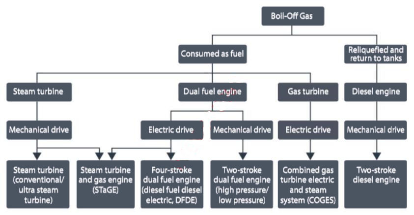
The propulsion system for an LNGC is closely related to the generation of and the manner in which the BOG is handled.
The key issues in the design/re-design of propulsion systems for LNGCs were:
- fuel flexibility;
- reliability;
- availability;
- safety.
Comparison of alternative concepts of LNGC propulsion and auxiliary power generation had also consider the complexity of LNG transport, including the increasing diversity of the commercial LNG market and charterer’s requirements.
| Propulsion types available and their associated characteristics | |||
|---|---|---|---|
| Propulsion Type | LNG Fuel Consumption | Average Ship Capacity | Typical Age |
| Steam | 175 t/d | < 150 000 | > 10 |
| DFDE/TFDE | 130 t/d | 150 000 – 180 000 | < 15 |
| ME-GI | 110 t/d | 150 000 – 180 000 | < 5 |
| X-DF | 108 t/d | 150 000 – 180 000 | < 1 |
| Steam Re-heat | 140 t/d | 150 000 – 180 000 | < 1 |
| Note: LNG fuel consumption figures in the table above are at designed service speeds. | |||
Steam turbines
What is steam turbines?
Steam turbines – steam turbine installations are acknowledged as a well proven and reliable propulsion system. Steam turbine installations require only a modest amount of pre-scheduled maintenance, the timing of which can usually coincide with the scheduled refit periods of the ship.
The ease with which Types of propulsion systems on ships carrying LNGsteam turbine installations can burn boil-off gas and their reliability kept them in the controlling position over diesel engine installations. However, they are not very efficient when compared to diesel engines and this has had a negative impact on the operating economy and exhaust gas emissions of the ship.
Safety is of utmost importance in gas shipping, and LNGCs have an excellent safety record. The reliability of steam turbine propulsion has helped to achieve this, together with strict terminal regulations and procedures and robust ship designs. Propulsion power has to be available at all times while in port.
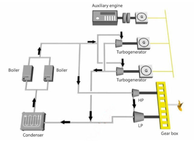
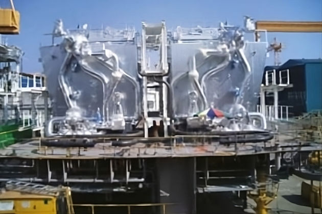
A steam propulsion plant with turbines is usually comprised of two boilers with a generating capacity of 80-90 t/h of superheated steam, at a pressure of 60 bar and +515 °C.
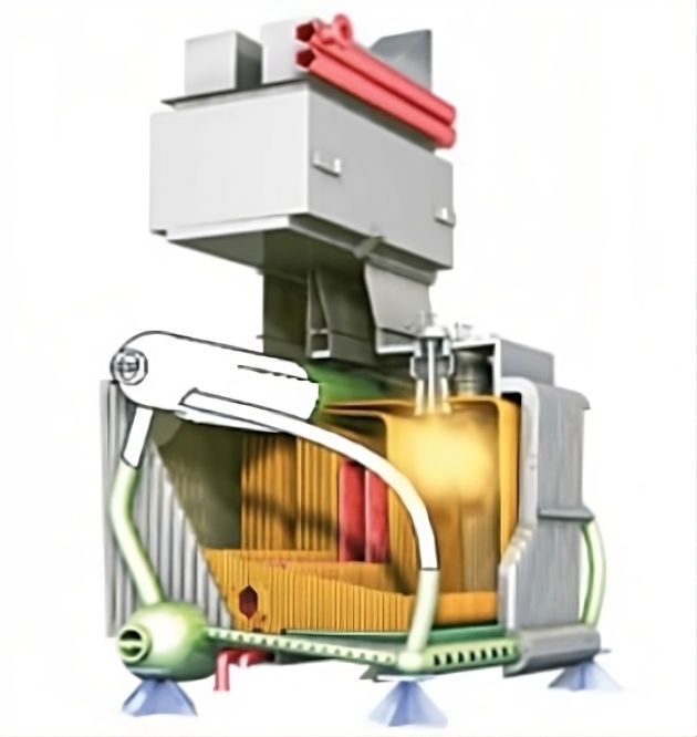
The two boilers generate sufficient steam for the main propulsion turbines and auxiliary engines. The boilers are designed to have single or dual fuel capabilities at varying loads, giving versatility to the system.
For steam ships, a vital procedure in the case of a boiler flameout is to purge all gas from the boilers before attempting re-ignition. Without such care, boiler explosions are possible and occasional accidents of this type have occurred.
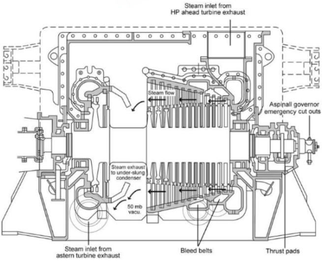
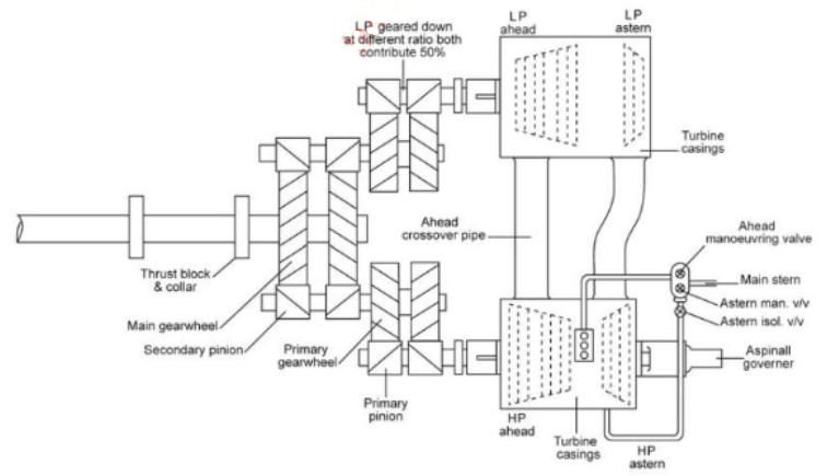
The arrangement of the turbines is, typically, cross-compound, with a net power of between 35-45 MW. The steam, once expanded in both turbines, is condensed in the main condenser and returned to the boilers by pumps that pass through a number of heaters (LP heater, HP heater, etc.). This takes advantage of residual heat, increasing the thermal efficiency of the cycle. Once in the boiler, the corresponding change of state occurs again through the input of heat, returning again to steam phase and closing the cycle.
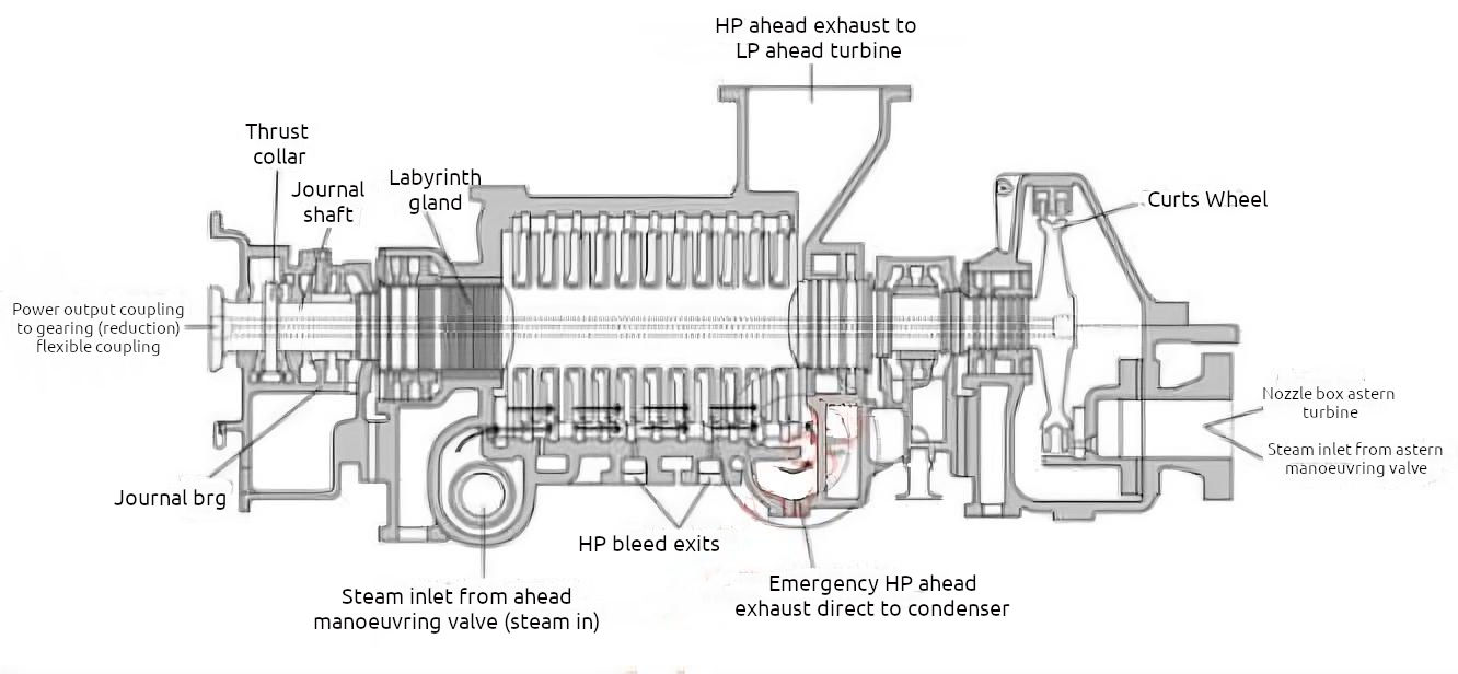
Steam propulsion turbines are installed horizontally and work by converting the potential energy in the superheated steam (from the boilers) into rotary motion. Passing high pressure steam through a HP turbine and then through an LP turbine is known as a “compound reaction turbine”. The term “compounding” describes the process that reduces the steam pressure from -60 mbar when it leaves the boiler, to -60 mbar when it leaves the LP turbine and enters the main condenser.
It is the action of the steam on the rotor blades that creates the force that turns the rotor. The steam is like wind acting on a windmill.
The control valves that allow steam to the ahead or astern turbines are known as the manoeuvring valves:
- ahead manoeuvring valve, which allows steam to pass proportionally to the power demand;
- astern manoeuvring valve, which allows steam to the guardian valve and the astern turbine;
- guardian valve, which is an astern steam isolating valve, providing a double shut off facility. This is operated by an independent system.
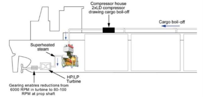
The turbine shafts rotate at speeds of up to 6 000 rpm. This speed has to be reduced, by a system of gearing (see Figure 8), to a propeller shaft speed of 80-100 rpm. This Is deemed to be the most efficient shaft speed range for marine propulsion.
When warming up, when warmed or when cooling down, the steam turbine rotors must not be allowed to remain stationary for more than a few minutes as this could cause the rotor to sag, which would result In high vibrations and possible failure.
The generation of electrical power on board was traditionally provided by two steam turbo generators which are fed from the boilers. Each generator had an average power of 10 MW which, together with a diesel generator(s) of around 3 MW, was sufficient to meet the power demand of the ship in any given situation.
An advantage of the steam turbine system is the fact that no GCU is necessary. All BOG is consumed in the boilers. The supply of gas from the cargo tanks to the boilers is performed through a single stage centrifugal low duty (LD) compressor and heater (for redundancy there are normally two LD compressors and two heaters fitted). The Low Duty Compressor(s) on the Liquefied Natural Gas CarriersLD compressors have variable pitch blades and are driven by either a steam turbine or a variable speed electric motor, regulating the gas supply to the boilers, depending on the demand.
The excess of BOG generated while the ship is in port or at anchor, or when the propulsion system is out of service, is consumed in the boilers. This produces steam that is sent directly to the main or auxiliary condenser after passing through a laminating and tempering process known as “dumping”. This process provides the capacity to stabilise the pressure in the cargo tanks
The maximum total plant efficiency of the steam propulsion system is approximately 30 % at full load and the efficiency becomes lower as the turbine load decreases. The efficiency of the turbo generators is lower than the main propulsion turbine. The low thermal efficiency and the resulting higher cargo transport costs are clear disadvantages, as is the requirement for a larger engine room. Large LNGCs require more power than existing steam-turbine designs can deliver. Moreover, manning the ships with engineers that are qualified to operate steam-turbine systems is becoming more difficult as the technology loses market share.
As other segments of the shipping industry have already switched to diesel engine power during the previous decades, the pool of experienced and qualified steam engineers is rapidly shrinking, posing a crewing challenge that can reflect in manning costs.
Current turbine manufacturers. The manufacture of marine steam turbines is now limited to a few suppliers and licensees (primarily Japanese and Malaysian owners).
Comparison of advantages/disadvantages of conventional steam turbine plant
| Conventional Steam Turbine Plant | |
|---|---|
| Advantages | Disadvantages |
| Proven track record and reliable plant performance | Highest fuel consumption, lowest overall plant efficiency |
| Maintenance requirements in service – very low and usually achievable by ship’s staff | Current ship design only allows for single screw ships and accepted max power output of 34 MW |
| Down time in port rarely required | Limited manoeuvring flexibility due to high inertia characteristics, with insufficient astern power to pull the ship free of ice if required |
| Flexibility of fuel selection: flexible burning of any fuel combination, oil only, gas only and dual. Full load steam dump systems manage additional cargo boil-off requirements | Diminishing operator experience industry-wide due to marine diesel propulsion dominance |
| Most shipyards able to provide steam plant experience for refit | Limited number of marine steam turbine manufacturers |
| Uniform torque under load | Age profile of the experienced service engineers |
| Low lube oil cost | Relatively large E/R volume required, reducing cargo carrying capacity |
| Large power to weight ratio | High rotor speeds require reduction gearing to the propeller shaft |
| Reliquefaction plant and GCU not required | Turbine is not directly reversible, astern turbine is required |
| No redundancy is required for the steam turbine, gear box or the propeller | |