Discover the role of Low Duty (LD) compressor in LNG carrier cargo systems. Explore how low-duty compressors facilitate efficient handling and transportation of liquefied natural gas. Uncover the advantages and operational significance of LD compressors in optimizing LNG carrier cargo systems.
Reference: SIGTTO “LNG Shipping Suggested Competency Standards”, Sections:
1 Have an awareness of their purpose and operating principles.
2 Know and understand design features:
- blower;
- driving mechanisms;
- capacity control mechanisms;
- shaft sealing arrangements;
- bulkhead sealing arrangements;
- principles of operation and purpose of surge control.
3 Know and understand operational requirements and procedures:
- setting up:
- nitrogen sealing;
- lubrication.
- automatic control requirements;
- starting of 2nd compressor;
- shutdown.
4 Know and understand their alarm settings and resulting actions.
The majority of LNGCs are fitted with LD compressors. However, some have dual purpose LD/HD compressors or, depending on the propulsion system, some may use reciprocating compressors.
On passage, the natural boil-off gas (NBOG) rate can vary through changes in the barometric pressure, ambient temperature and the sea conditions. The NBOG will also vary according to the age and design of the Cargo containment system of gas vesselcontainment system and may be between 0,07 % and 0,15 % of the cargo volume per day.
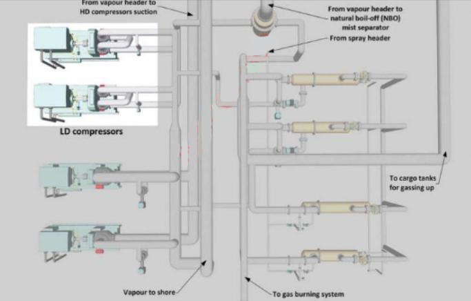
On LNGCs fitted with centrifugal LD compressors, it is normal for two compressors to be installed in the cargo machinery room (CMR). These compressors are used to compress the NBOG so that it can be used as fuel in the main propulsion plant or generator engines or disposed of in the GCU.The compressors are generally axial in-flow, multi-stage design with 2-6 stages being common. Normally, only one of the LD compressors is in use at any time, with no automatic changeover facility provided in the event of a compressor trip.
In “gas only” mode, the boil-off gas (BOG) to dual-fuel (DF) engines is often a mix of natural boil-off gas (NBOG) and forced boil-off gas (FBOG).
The Use of Vaporisers on Liquefied Natural Gas Carriersforcing vaporiser (FV) must supply the remaining requirement between the actual fuel gas consumption and NBOG.
The LD compressors are designed to maintain the BOG fuel gas supply pressure.
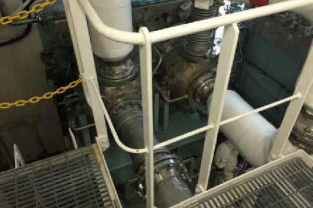
Compressor system
Typically, each LD compressor is skid-mounted and consists of two (or more) direct coupled compressors with an integral gearbox and sub-systems as follows:
- a self-contained LO system for the gears and rotor bearings;
- a seal gas system;
- an alarm and trip system;
- an inter-cooler;
- an after-cooler;
- a variable diffuser vane (VDV) actuator;
- an oil mist separator;
- LO sump tank immersion heater;
- a gear-driven main LO pump;
- an electrically driven auxiliary LO pump;
- an LO cooler;
- a duplex oil filter;
- a low speed gear coupling;
- a bulkhead/shaft seal;
- a main drive electric motor.
Driving mechanisms
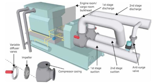
The LD compressors are driven by electric motors supplied from the main cargo switchboards. The motors are installed in an adjacent electric motor room (EMR) that is segregated from the compressor room by a gas-tight steel bulkhead. The drive shaft between the motor and the compressor penetrates the bulkhead via a gas-tight mechanical seal operated with a pressurised oil barrier.
The compressors can be operated either locally in the CMR or remotely from the IAS. When in use, the capacity of the compressors can be regulated and controlled by the variable diffuser vanes, with the travel indication being shown both locally and on the IAS.
Compressors’ motors are generally limited to a maximum of three starts per hour when starting from a cold condition or two starts per hour from a warm condition.
| LD compressor/typical details (will vary dependent on ship type) | |
|---|---|
| No. stages | centrifugal, four stages, dual speed with variable diffuser vanes |
| Capacity | 4 430 m3/h |
| No. on board | 2 |
| Suction temperature | minus 91 °C (-91 °C) |
| Discharge temperature | +105 °C |
| Suction pressure | 1,0 bar |
| Discharge pressure | 6,5 bar |
| Power | 760 kW |
| Shaft speed | 29 140 rpm |
| Capacity | 6 600 V, 760 kW |
| Motor speed | 3 450 rpm |
Capacity control mechanisms
To achieve the required gas flow, the compressors have variable diffuser vanes (VDVs) fitted. These vanes are operated by pneumatic actuators that receive control signals from the IAS.
The LD compressor output/fuel gas header pressure is controlled by changing the position of the VDVs. To prevent rapid changes and surging in the compressor gas discharge, the output from the controller is limited to ensure that the design pressure for the gas burning system is maintained at all times.
Shaft sealing arrangements
A seal gas system is fitted between the compressors and the gearbox to prevent LO mist from entering the process stream and to prevent the flow of cold process gas into the gearbox. The seal gas is injected between the gear shaft and the compressor wheel on the compressor. N2 is produced by the onboard N2 generators and the pressure is regulated by control valves mounted on the compressor skids.
The seal gas system is regulated by the control valves so that the seal gas pressure is a function of the compressor outlet pressure. Any seal gas entering the gearbox from the shaft seals is returned to the LO sump, separated from the oil and vented to atmosphere via a mist separator and a vent on the top of the compressor housing.
Bulkhead sealing arrangements
In a typical LD compressor configuration, the LO is stored in a vented LO sump (typically 1 300 litres). An integrated steam immersion heater with a thermostatic temperature control valve is fitted in the sump to maintain a constant positive temperature of at least +25 °C, avoiding condensation when the compressors are stopped.
Read also: High Duty Compressor(s) on the Liquefied Natural Gas Carriers
LO is supplied from the sump through separate suction strainer screens and one of the two LO pumps. The discharge from the LO pumps passes through check valves to a common LO supply rail feeding the gearbox, bearings and bulkhead seal. The main operational pump is driven by the high-speed shaft gear. In the event of failure of the driven pump, the IAS automatically starts the standby electric motor driven auxiliary pump and an alarm is activated. The electrically driven auxiliary pump is used when starting the compressors.
Temperature sensors are fitted to monitor the oil outlet temperature of the gear bearings. Should the temperature rise above pre-set values, an alarm will be activated.
The flow of oil and the oil pressure to the bulkhead seal are controlled by an orifice. The oil is used for the lubrication of the bulkhead shaft seal and returns back to the LO sump tank
Principles of operation and purpose of surge control
An automatic surge control system is usually provided to ensure that the compressor flow rate does not fall below the designed minimum. Below this rate, the gas flow will not be stable and the compressor will be liable to surge, causing shaft vibration that may result in damage.
A surge control system consists of:
- a flow transmitter;
- a compressor differential pressure transmitter;
- a ratio station;
- an anti-surge controller;
- a surge control/recirculation valve on the gas stream.
On the basis of a pre-set ratio between the gas flow and compressor differential pressure signals, the anti-surge controller will produce a signal that modulates a surge control valve.
Bulkhead shaft seal
Each compressor shaft is equipped with a force lubricated bulkhead shaft seal, which prevents combustible gas from entering the EMR. The lubrication is supplied from the LD compressor LO system. The LO system feeds the following:
- journal bearing on both sides of the high-speed shaft;
- journal bearing on the driven end of the low-speed shaft;
- integral thrust and journal bearing on the non-driven end of the low-speed shaft;
- sprayers for the gear wheels;
- LD compressor bulkhead seal.
Starting
Starting instructions
Compressors can be started and stopped either locally or from the IAS.
Operating Procedures. Always refer to the manufacturer’s manual for specific instructions.
To prepare a typical LD compressor for running:
- confirm power available;
- start the LO heater about 75 minutes (depending on ambient temperature) prior to expected compressor start-up;
- open system specific manual valves;
- check that VDVs are closed and in automatic mode;
- close the seal chamber vent line valve;
- open the N2 seal gas supply manual valve;
- open compressor suction and discharge valves;
- run the auxiliary LO pump for about 30 minutes to warm up the system and check for leaks. The temperature in the LO sump tank is a controlled function. Do not operate the auxiliary LO pump at temperatures below manufacturers’ recommendations.
- open the LO cooler inlet and outlet cooling water valves (usually left open);
- open the instrument air supply to the control panel;
- switch on the power to the control cabinet.
On the IAS:
- select the appropriate IAS mimic for the LD compressor automatic start;
- press the reset button;
- the message “Ready to Start” (or similar) should appear on the mimic display when all safety circuits are healthy;
- start the compressor motor (half speed or full speed). If half speed is selected, the full speed button will need to be pressed once the desired inlet temperature is reached;
- the auxiliary LO pump will stop when the compressor driven pump is delivering full system pressure.
Note: On the older class of LNGC (GT/TGZ), gas compressors for both HD and LD service have steam turbines as the prime mover. On these installations, capacity control is arranged by speed control of the turbine, without the benefit of inlet guide vanes. The drive between the turbine and compressor is straight-through, i. e. without reduction gearing. Because of the absence of an electrical prime mover, a dedicated motor room with accompanying bulkhead shafting/sealing is unnecessary. The modular turbine/compressor set is housed in the gas compressor house.
LD compressor trips
Typically, the following conditions will cause the compressors to trip:
- ESD trigger;
- electrical power failure;
- bearing high temperature;
- high gas discharge pressure;
- excessive rotor vibration;
- low lube oil pressure to gearbox;
- high bulkhead seal oil temperature;
- low lube oil pressure to bulkhead seal;
- low seal gas pressure;
- manual trip signal.
Mist separator
An LNGC normally has a mist separator fitted in the cargo system. The mist separator would generally have a capacity of 1 500 to 6 000 m3/h.
When utilising BOG–NBOG/FBOG – as fuel for the ship’s main generating/propulsion plants, to prevent damage it is essential that no LNG is carried over into the suction of the LD compressor.
During any FBOG operations, NBOG would still be utilised. When FBOG is added to NBOG, the two “gases” which have different compositions and temperatures, are mixed. Where there is a large mixing range, a “mist” will be created at the mixing point, from the two essentially dry gases. For this reason, BOG passes through a mist separator before reaching the LD compressor suction to protect the LD compressor impellers.
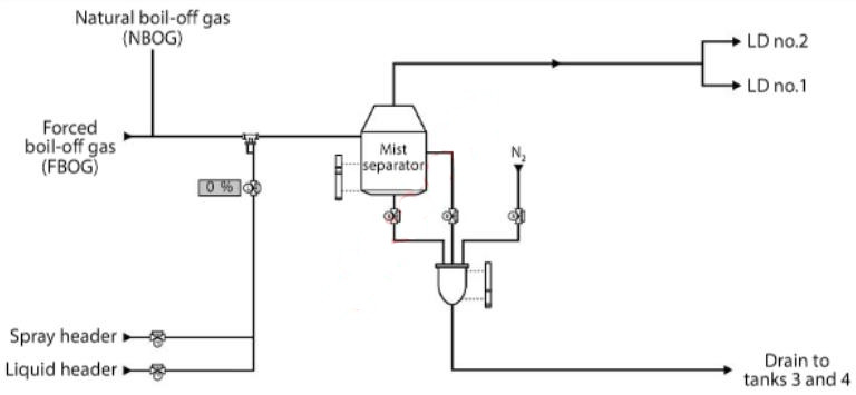
The mist separator,which is installed in a vertical plane, has inlet nozzles from the NBOG and FBOG headers and one outlet nozzle to the LD compressors.The unit is designed to eliminate 99-99,5 % of any mist created.
Any LNG droplets formed inside the mist separator are directed to the bottom of the unit and into a sealed drain pot. An automatic drain sequence,incorporating N2, then forces the LNG droplets out of the drain pot and into the liquid domes of designated cargo tanks (generally No. 3 or No. 4).There is also an option for the drain sequence to be carried out manually.