Discover the latest advancements in satellite technology, focusing on electric propulsion systems and innovative launch platforms. This article covers various engine types, including ion engines and Hall Effect Thrusters, and highlights key industry players like SpaceX and Sea Launch. Learn about the benefits and challenges of electric propulsion and the essentials of station-keeping in modern space exploration.
- Appendix 8A Transponder Costs
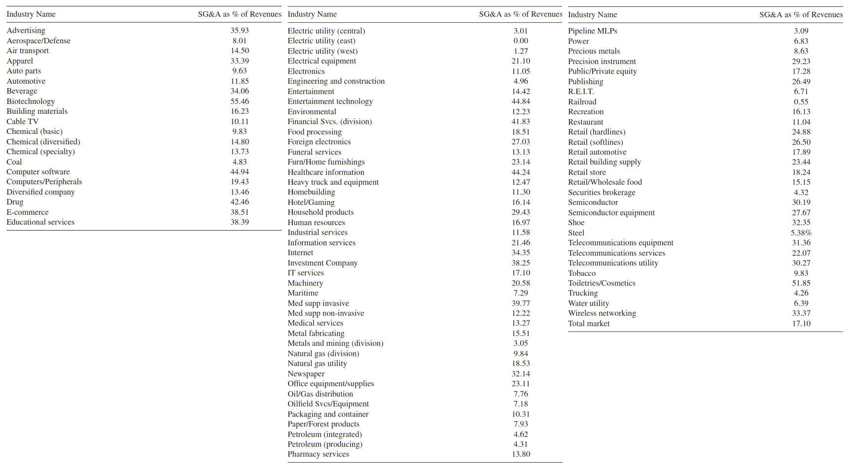
- Typical SG&A and Ebitda for the General Commercial World and Satellite Firms
- Transponder Costs
- Basic Technology and Approach for Electric Propulsion
- EP Engines
- Ion Engines
- Hall Effect Thrusters
- MagnetoPlasma Dynamic Thruster
- Advantages and Disadvantages of All-EP
- Basics about Station-Keeping
- Industry Approaches
- New Approaches and Players for Launch Platforms
- Space Exploration Technologies Corporation (SpaceX)
- Sea Launch
- Traditional Launchers
In this article we provide a basic survey of two developments related to the deployment of satellites:
- electric propulsion (EP) and,
- new launch platforms.
Each of these advances can ultimately reduce the cost of commercial satellite communications, thus improving their competiveness compared with terrestrial transmission, in appropriate application segments.
It should be noted, however, that there are other ways also to improve the competiveness of satellite services, namely, direct price reduction. Price reduction can be achieved by further optimizing the operations (also known as run-the-engine) costs. For example, the satellite operators are, in a number of instances, swamped with superfluously redundant, zero-revenue, negative cash-flow ground infrastructure and staff in outdated, often overbuilt, “ungreen” teleports; one way to address costs is to consolidate these inefficient teleports and outsource the ground infrastructure function to companies with much lower overhead and personnel costs and with nimble management.
Additionally, advantageously to the operators and their shareholders but disadvantageously to the user/consumer, the Earnings Before Insurance, Tax, Depreciation, and Amortization (EBITDA) of satellite operators is kept at around 75–85 % by these operators. A commercial spacecraft on station may typically cost $150 M (including on-the-ground Ground Control System [GCS]); with a 15-year lifecycle, and, say 48 transponders (24 at C-band and 24 at Ku band), the yearly cost per transponder could thus be $208 333; adding a 20 % operating cost The 15-year total operations cost per spacecraft for a large operator (where staff/infrastructure efficiencies ought to apply) was independently computed to be $5,75–11,5M in 2003, or in the range of $7,5–15M in 2014 (with a 3 % annual inflation rate). Even taking the higher of these two numbers, that would equate to $1 M/year/satellite, or $20 000/transponder/year; our assumption of a 20 % markup on the annualized equipment cost cited above is more than double this industry-documented figure for the operations cost. Looking at this issue from another perspective, an operator with, say 60 spacecraft would have, under our 20 % ops markup heuristic, a yearly run-the-engine budget of $120 M; that would seem to be a fairly substantial generous figure to live on and at the same time still charge the user $417 K/year/transponder, rather than $1 600 000 – any discrepancy could be addressed by the operator making an explicit commitment to deprecate intrinsic inertia fostered by middle management and by proper reengineering of the operations function to be more cost-effective and less elephantine.x factor, adding a 22 % Selling, General & Administrative Expense (SG&A) (See DVB-S2 Modulation Extensions and Other Advances“Partial Listing of System-Level us Patents for Spot-Beam/Multi-Beam Satellites”), and adding a 8 % profit factor, brings this figure to around $312 500; even assuming a partial 75 % transponder fill rate, the figures would be $278 000 and $416 666, respectively. However, the typical yearly transponder fee charged by satellite operators are, on the average, much higher, specifically (See DVB-S2 Modulation Extensions and Other Advances“Partial Listing of System-Level us Patents for Spot-Beam/Multi-Beam Satellites”) $1,6 M. Clearly, there are opportunities for price reductions by improved corporate management, besides various technical innovations.
Appendix 8A Transponder Costs
This appendix has two sections; the first assesses EBITDA for various industries; the second looks at transponder costs.
Typical SG&A and Ebitda for the General Commercial World and Satellite Firms
New York University Stern School of Business published the EBITDA as a percentage of sales for 7 766 firms, such figure being 14,7 %. See table below.
| EBITDA by Industry (New York University Stern School of Business Data) | ||
|---|---|---|
| Industry Name | Number of Firms in Study | EBITDA/Sales (%) |
| Utility (water) | 20 | 42.50 |
| Precious metals | 166 | 42.36 |
| Oil/Gas (production and exploration) | 411 | 42.09 |
| Tobacco | 12 | 41.50 |
| Railroad | 10 | 37.71 |
| Pharma and drugs | 138 | 34.02 |
| Computer software | 273 | 30.75 |
| Cable TV | 16 | 28.96 |
| Semiconductor | 104 | 27.61 |
| Broadcasting | 30 | 27.45 |
| Information services | 71 | 27.44 |
| Utility (general) | 20 | 27.32 |
| Power | 106 | 26.90 |
| Healthcare equipment | 193 | 26.43 |
| Telecommunications services | 82 | 25.68 |
| Internet software and services | 330 | 23.50 |
| Telecommunications equipment | 131 | 23.36 |
| Entertainment | 85 | 22.99 |
| Metals and mining | 134 | 22.90 |
| Computers/Peripherals | 66 | 22.64 |
| Beverage (alcoholic) | 19 | 22.38 |
| Biotechnology | 349 | 22.31 |
| Hotel/Gaming | 89 | 22.13 |
| Real estate (general/diversified) | 11 | 21.96 |
| Beverage | 47 | 21.54 |
| Oil/Gas (integrated) | 8 | 21.10 |
| Diversified | 20 | 20.30 |
| Coal and related energy | 45 | 20.03 |
| Chemical (specialty) | 100 | 19.60 |
| Restaurant | 84 | 19.60 |
| Telecom (wireless) | 28 | 19.28 |
| Household products | 139 | 19.23 |
| Insurance (general) | 26 | 19.21 |
| Environmental and waste services | 108 | 18.71 |
| Healthcare information and technology | 125 | 18.58 |
| Recreation | 70 | 18.15 |
| Healthcare products | 58 | 17.58 |
| Semiconductor equipment | 51 | 16.15 |
| Shipbuilding and marine | 14 | 15.85 |
| Healthcare facilities | 47 | 15.79 |
| Publishing and newspapers | 52 | 15.78 |
| Electrical equipment | 135 | 15.63 |
| Advertising | 65 | 15.52 |
| Educational services | 40 | 15,38 |
| Machinery | 141 | 15,26 |
| Heavy construction | 46 | 14,38 |
| Apparel | 70 | 14,23 |
| Chemical (diversified) | 10 | 14,22 |
| Chemical (basic) | 47 | 14,11 |
| Packaging and container | 24 | 13,61 |
| Construction | 18 | 13,60 |
| Trucking (see reference for rest of table) | 28 | 13,29 |
| Total | 77 663 | 14,17 |
Table below focuses more closely to the wireless/satellite industry, based on data from Deloitte.
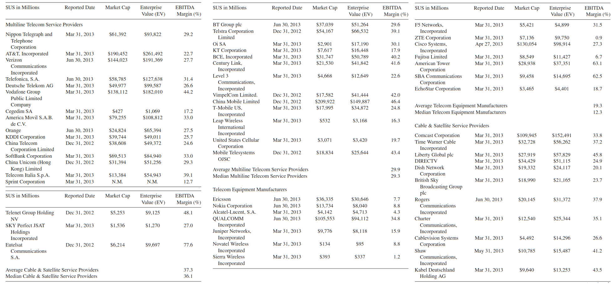
Table below depicts the Selling, General & Administrative Expense (SG&A) costs of major industries. The average SG&A is 17 %; for the aerospace industry it is 8 % and for the wireless industry is 33 % (if we used an average between these two industries, the average is 21 %, right on-mark with a telecom industry SG&A of 22 %).
Transponder Costs
The article that follows intrinsically makes important observations.
The average price of leasing a telecommunications satellite transponder increased just about everywhere in 2011 except in North America, the Middle East and North Africa, according to a market assessment released August 23, 2012. The report by Euroconsult of Paris said the average transponder price of $1,62 million per year for 36 megahertz of capacity hides a wide regional price disparity. The report says there is a “risk of price erosion” in the coming years as some markets soften with new satellites entering service. As has been the case for years, Western Europe continues to be the highest-price market for leasing satellite bandwidth, at an average of $3,2 million per transponder in 2011, Euroconsult said.
Northeast Asia featured the second-most-costly transponders, at $2,6 million per transponder per year, followed by the region around Australia and New Zealand, where prices averaged $1,7 million per year. The least-expensive transponders were to be found in South Asia, where prices averaged only slightly more than $1 million per transponder per year. Satellite operators have said that absent revolution in satellite or launch costs, $1 million is a kind of threshold price below which it is difficult to make a profit.
For some smaller satellite operators financed by their governments, making a profit may not be a primary concern. As these operators proliferate, their approach to the market may affect the business models of the established operators for which profitability is the principal motivation. Not surprisingly, North America appears in the Euroconsult report as a place where overall market size and prices, at around $1,4 million per transponder per year, have been flat in recent years and are likely to remain so for some time.
Euroconsult said that for the operators of fixed satellite services that report financial results, the average EBITDA – earnings before interest, taxes, depreciation and amortization – was 75 percent of revenue in 2011. But as with transponder prices, this figure masked wide variations, with the most profitable operators reporting 80 percent EBITDA margins, while others reported margins of 50 percent. Television broadcasts remain the core of the market’s profitability as demand for high-definition television programming, which requires more bandwidth, has outpaced advances in video compression that puts downward pressure on bandwidth demand.
Global military demand for commercial fixed satellite services bandwidth, which has been led by the US Defense Department, is likely to decrease in the coming years with the winding down of US-led military coalition activity in Afghanistan and Iraq, Euroconsult said. But countering this trend will be growth in US military use of Ka-band satellite broadcast frequencies. The US military spent more than $450 million purchasing conventional commercial fixed satellite service capacity in 2011, according to Euroconsult. To this figure is added L-band capacity purchases from mobile satellite services operators such as Iridium of McClean, Va., and Inmarsat of London.
One of the highest-growth segments of the telecommunications satellite industry is in delivering broadband Internet access to unserved or underserved areas. A new generation of platforms, called high-throughput satellites, is being fielded in North America, Europe and Australia, with more to come in other regions, according to most market assessments. Euroconsult forecasts that high-throughput satellites, which provided 35 gigabits per second of capacity worldwide, will be beaming around 850 gigabits per second in a decade’s time. More than half that capacity will be used to provide consumers with broadband access from their homes. North America, which has been the biggest early adopter of satellite broadband despite insignificant government support, will remain the biggest market for this technology through the next decade, Euroconsult said. ViaSat Inc. of Carlsbad, Calif., and Englewood, Colo.-based EchoStar Corp.’s Hughes division are both deploying high-throughput satellites for their established consumer broadband businesses.
Basic Technology and Approach for Electric Propulsion
Work on EP for commercial satellites goes back to the 1980s. In principle, EP can be used for some of the propulsion function of a spacecraft, or for all propulsion functions – obviously the spacecraft design has to match the stated operator’s propulsion policy. “All-electric propulsion” (all-EP) is a topic receiving a lot of attention of late. All-EP offers the opportunity to reduce the spacecraft mass and the launch costs; however, the technology is not yet fully tested for commercial applications, especially in terms of multiple missions with multiple operational spans. Clearly, there are competing tradeoffs in selecting a satellite configuration: larger satellites allow for larger payloads and higher power levels and, thus, support enhanced revenue generating capabilities; however, heavier satellites cost more to manufacture and require more powerful and more expensive launch vehicles.
We saw in Exploring the Future of Satellites“Trends, Technologies and Applications of Modern Satellites” that the launch rocket places the spacecraft into an initial (or “transfer”) orbit just a few 100 miles above the earth’s surface; the satellite must then propel itself into its final operating orbit. This process normally takes from several days to several weeks; this process entails traversing the radiation belts mentioned in High Throughput Satellites (HTS) and KA/KU Spot Beam Technologies“Applications and Design Considerations of HTS Satellites”, which preferably is done in an expeditious manner. Once on-station, the spacecraft must be kept at the specified orbital location. During the lifecycle (say, 15 years) it may be desirable to relocate the spacecraft to some other orbital location to serve different markets, or to support a Bring Into Use (BIU) mission (this to secure orbital rights by actually being present/operating at a “granted” location). To be able to support these activities, the spacecraft must be equipped with a number of (small) thrusters.
Focusing specifically on Geosynchronous Orbit (GSO) applications, a GSO spacecraft requires propulsion systems from its separation from the third stage of the launcher until the de-orbiting operation, years later. At this separation with the third stage, the satellite is injected on a transfer orbit with an apogee at 36 000 km from the earth surface; at the apogee of this orbit an applied thrust of 1–3 N gives an increment of velocity of ∼2 m/s and moves the satellite to a quasi-circular and quasi-equatorial orbit. Additional maneuvering and In Orbit Testing (IoT) are required to make the spacecraft’s orbit circular and equatorial, to open solar panels, to verify the instruments, to modify the satellite attitude and to set the satellite at its working longitude. This process usually takes a couple of months. The satellite has to be maintained at this working position throughout the mission (15–20 years).
However, the satellite moves in 3-dimensional space in accordance with lunar and sun trajectories, inhomogeneity of the earth’s gravitational pull, and radiative sun pressure. At the altitude of the GSO the predominant effect is the lunar-solar interactions, these effects being greater than the earth inhomogeneity and the sun radiation effects. Consequently, spacecraft thrusters are required to bring the satellite back to its nominal (initial) working place, and to perform daily north–south and east–west corrections. The thrusters deliver a thrust in the range 80–100 mN; the variation of velocity is 50 m/s (north–south) and 5 m/s (east–west) per year. In the vacuum of space one achieves movement through reactive forces, ejecting matter in one direction and achieving movement in the opposite direction.
Further to the discussion above, a spacecraft requires propulsion for the following reasons:
- To transition from the Launch and Early Orbit Phase (LEOP), to the parking orbit, to the intermediate orbit, to the transfer orbit, to the target orbit. This activity (known in aggregate as “orbit raising”) is seen by some as being comprised of a “orbit topping” phase where the satellite is brought up close to the target orbit and a “final GSO insertion” phase;
- To maintain the satellite on-station within the permitted box (as granted by regulatory entities); this is done via the telemetry, tracking and command (TT&C) mechanism and the GCS;
- To relocate the spacecraft to other GSO locations to support new traffic opportunities at new orbital slots;
- To move the satellite during the mission to avoid a collision with an object (debris) moving in space and;
- To de-orbit the spacecraft at the end of its mission (the de-orbiting is achieved with an increment of velocity ΔV = 3 m∕s in order to send the satellite on a higher orbit of about 200 miles).
Currently there are two approaches to (spacecraft) propulsion. The traditional method is fully-chemical propulsion; it uses chemical reactions to produce a flow of fast-moving hot gas, thereby providing a push thrust. The newer method uses the electrical power that can be generated from sunlight with solar photovoltaic panels to propel the spacecraft using a number of atomic/subatomic particle ejection, thereby providing a push thrust. Electric thrusting of propellants is useful only for interorbital transportation, not for launch from the Earth’s or Moon’s surface. As seen in Table 1, and alluded to earlier, spacecraft may use a combination of both methods (a hybrid arrangement), with EP currently being used almost exclusively for station-keeping – this EP approach has been used on some commercial satellites since the 1980s.
| Table 1. Possible Application of Various Propulsion Methods | |||||
|---|---|---|---|---|---|
| Activity | All-Chemical | Hybrid Chemical | Electric | All-Electric (All-EP) | |
| Orbit raising | Orbit topping | Used | Used | Used | |
| Final Insertion | Used | Used | Used | ||
| Station-keeping | Used | Used | Used | ||
| Relocations | Used | Used | Used | ||
| Emergency collision avoidance | Used | Used | Used | ||
| De-orbit | Used | Used | Perhaps used | Used | |
Or, the spacecraft could use all-EP, this being the latest innovation, now being commercially investigated. The adoption of EP technology has already brought a number of benefits, including longer operational life and increased satellite dry mass for a given launch mass (and conversely, decreased launch mass for a given payload mass). For commercial satellite operators, these factors directly translate into the ability to decrease costs for equivalent satellite capability and increase the amount of total life revenue generated by a given satellite. Hence, the key technical and business question at this juncture is: “Should the operator chose to go all-EP on new procurements?”
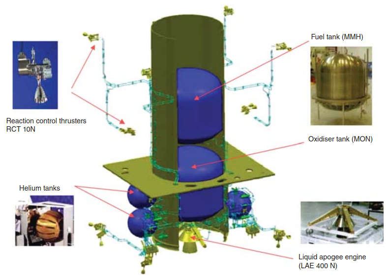
At this time, spacecraft propulsion for commercial GSO satellites is typically supported by chemical propellant systems, especially for environments where long orbital drifts are contemplated at various points in the spacecraft’s mission. Specifically, powerful chemical propulsion engines are used to quickly move satellites through Earth’s hazardous radiation belt. The issue is that chemical propellants add launch weight and eventually are exhausted (typically in 15 years). With chemical propulsion there needs to be one or two substances that can be burned in a controlled manner. The combustion takes place in a chamber and the resulting hot gases are ejected through an opening, the nozzle, to provide the desired thrust. Heating the gas in a chamber produces an increase in pressure and letting the gas escape through a small aperture produces a fast jet. By varying the amount of fuel burned and the shape of the nozzle, which controls the velocity of the exhaust gases coming out of the engine, or thruster, one can maneuver the satellite (note that in space thrusters must work without the oxygen present in the Earth’s atmosphere). Chemical propulsion is a complex process and a network of tanks, pipes, valves and delicate control mechanisms is needed; hence the desire to look at alternatives. For illustrative purposes Figures 1 and 2 from Thales Alenia Space depict a chemical bi-propellant propulsion system.
This kind of traditional thruster is usable for applications dealing with satellite orbit raising, east/west and north/south station-keeping, satellite attitude control, satellite attitude momentum control, and post-operational de-orbiting.
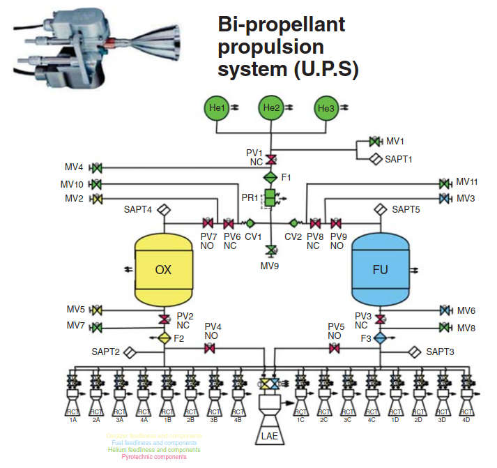
Key features (of this specific model, discussed for illustrative purposes) include: same propellant supply for all apogee maneuvers and station keeping maneuvers resulting in consumption optimization; bi-propellant system, so that thrusters are not prone to chemical degradation; 2-tank configuration, implying lower disturbances than with a 4-tank configuration, lower operational complexity, and avoidance of non-parallel depletion errors; all thrusters in stand-by mode to be operated at any time without any valve switching for activating branches, implying high availability, flexibility and reliability; and, liquid apogee engine multiple-burn capability providing high accuracy of insertion in GSO than other systems.
In terms of the underlying flight dynamics principles, the concept of EP and traditional propulsion are similar: a force is a push or a pull that acts upon an object as a result of its interaction with another object; some forces result from physical contact interactions, while other forces are the result of action-at-a-distance interactions (e. g., gravitational, electrical, and magnetic forces). According to Newton, whenever objects A and B interact with each other, they exert forces upon each other. These two forces are called action and reaction forces. Newton’s third law of motion states that for every action, there is an equal and opposite reaction. When gasses (or ions) are expelled from a nozzle on a spacecraft (thing being the topic at hand), they exercise pressure against atoms in the surrounding space (or surrounding electromagnetic field), thus generating thrust.
Rather lucid characterization of EP when noting that the science and technology of EP encompass a broad variety of strategies for achieving very high exhaust velocities in order to reduce the total propellant burden and the corresponding launch mass of present and future space transportation systems; and, when noting that these techniques group broadly into three categories:
- Electrothermal propulsion, wherein the propellant is electrically heated, then expanded thermodynamically through a nozzle;
- Electrostatic propulsion, wherein ionized propellant particles are accelerated through an electric field;
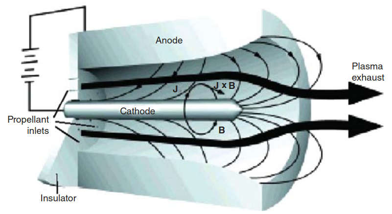
- Electromagnetic propulsion, wherein current driven through a propellant plasma interacts with an internal or external magnetic field to provide a stream-wise body force.
Such EP systems can produce a range of exhaust velocities and payload mass fractions an order of magnitude higher than that of the most advanced chemical rockets, which can thereby enable or substantially enhance many attractive space missions. The attainable thrust densities (thrust per unit exhaust area) of these systems are much lower, however, which, in turn, imply longer flight times and more complex mission trajectories. In addition, these systems require space-borne electric power supplies of low specific mass and high reliability, interfaced with suitable power processing equipment. Optimization of EP systems thus involves multidimensional trade-offs among mission objectives, propellant and power plant mass, trip time, internal and external environmental factors, and overall system reliability. A program of research and development of viable electric thrusters has been in progress for several decades, and over the past few years this has led to the increasing use of a number of EP systems on commercial and governmental spacecraft. Meanwhile, yet more advanced EP concepts have matured to high credibility for future mission applications.
Two broad tradeoffs come into play:
- The more energy available, the less propellant required, which in turn means less mass is required;
- The more time allowed for a space maneuver, the less power needed.
As noted, EP is an approach to accelerate a propellant (such as ions) through electro(magnetic) fields. The speed to which the propellant can be accelerated is a design consideration and the energy available on board is the other practical limitation. The simplest way to achieve EP is to replace the heat generated by combustion in chemical engines with electrical heating. Another way to heat a stream of gas is to use a controlled electrical discharge (arc). However, there are other, more sophisticated and more efficient ways of obtaining fast jets of gas. For example, ionized particles of propellant launched past a grid pushes the spacecraft in the opposite direction. Another possibility is to use the combined effect of an electric field to set the particles in motion and a magnetic field to accelerate particles of propellant. While with the use of an electric field alone, only charged particles of one polarity (opposite to that of the grid) provide propulsion, with the combined action of electric and magnetic fields both polarities are accelerated. EP typically implies high ion exhaust speed, this being much greater than in conventional (chemical) rockets. Also, much less propellant consumption is involved (implying higher efficiency in the fuel utilization). Continuous propulsion means applying a smaller thrust for a longer time. The propellant employed varies with the propulsion type, and can be a rare gas (e. g., xenon or argon), a liquid metal (e. g., cesium or indium) or, a conventional chemical propellant (e. g., hydrazine, ammonia, or nitrogen).
There are two commercialized EP technologies already utilized in space today, as follows:
- Some American interorbital satellites today use electric “ion drive” for stationkeeping. Ion drive is a simple and fairly mature technology (the Deep Space 1 probe, launched in October 1998, was the first vehicle to depend upon electric ion drive for all of its propulsion needs, to perform a close flyby of an asteroid).
- The Russians have used extensively an EP technique called a “plasma thruster” for at least 10 years, which they have begun to market overseas.
This thruster has been used in approximately one hundred Russian military satellites, but is relatively unknown in the west.
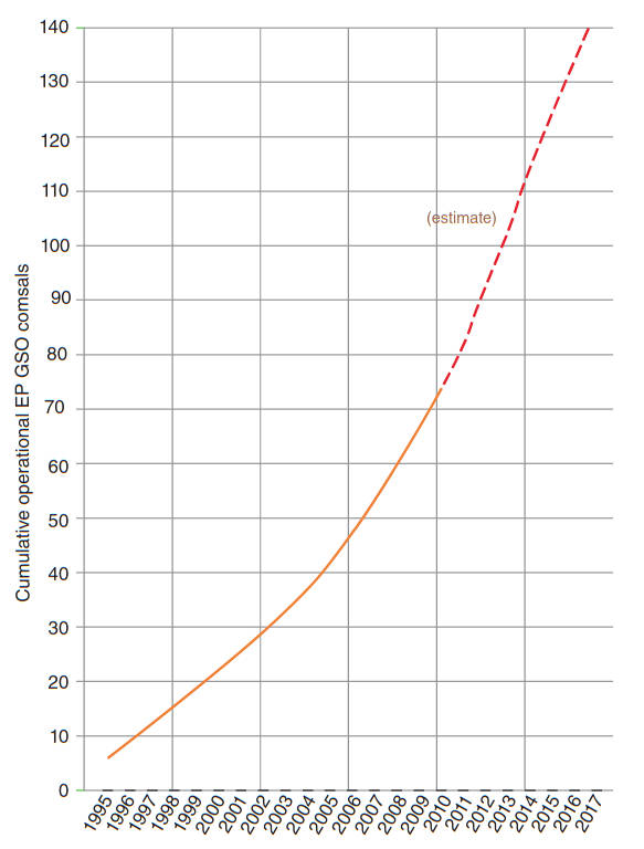
EP has a relatively long and successful history in the context of station-keeping (e. g., Boeing’s satellites have used ion thrusters for fine orbit control since 1997), but not with orbit raising, when satellites use their own propulsion system to reach orbit after separating from the rocket. Between 1995 and 2010 the cumulative number of operating GSO satellites that utilize EP for station-keeping increased more than ten-fold to over 70 spacecraft (see Figure 3).
EP Engines
There are a variety of potential approaches to accelerate ions or plasmas; most of these approaches utilize grids or electrodes (also see Table 2).
| Table 2. Key EP Concepts | |
|---|---|
| Concept | Definition |
| Arcjet | A device that heats a propellant stream by passing a high-current electrical arc through it, before the propellant is expanded through a downstream nozzle. |
| Electromagnetic propulsion | Propulsion wherein the propellant is accelerated under the combined action of electric and magnetic fields. |
| Electrostatic propulsion | Propulsion wherein the propellant is accelerated by direct application of electrostatic forces to ionized particles. |
| Electrothermal propulsion | Propulsion wherein the propellant is heated by some electrical process, then expanded through a suitable nozzle. |
| Hall effect | Conduction of electric current perpendicular to an applied electric field in a superimposed magnetic field. |
| Inductive thruster | Device that heats a propellant stream by means of an inductive discharge before the propellant is expanded through a downstream nozzle. |
| Ion thruster | Device that accelerates propellant ions by an electrostatic field. |
| Magnetoplasmadynamic thruster | Device that accelerates a propellant plasma by an internal or external magnetic field acting on an internal arc current. |
| Plasma | Heavily ionized state of matter, usually gaseous, composed of ions, electrons, and neutral atoms or molecules, that has sufficient electrical conductivity to carry substantial. |
| Resistojet | Device that heats a propellant stream by passing it through a resistively heated chamber before the propellant is expanded through a downstream nozzle. |
| Thrust | Unbalanced internal force exerted on a rocket during expulsion of its propellant mass. |
Some examples discussed in the literature include:
- Ion engine;
- Hall thruster (hall current thrusters [HCT]);
- MagnetoPlasma dynamic (MPD) thrusters;
- RF plasma thrusters (ECR, VASIMR, helicon double layer);
- Plasmoid accelerated thrusters.
The different types of EP have different performances and optimal applications. Some types are more suitable for missions requiring higher thrust levels to reduce the trip time, some are better for high-precision positioning (flight dynamics) applications, while others are better for long mission-duration (minimizing the use of propellant). The field of electric thrusters is very large and the suggested plasma sources are numerous. However, only a few have been (fully) tested, validated and used in space. Other propulsion systems are futuristic concepts. Table 3 based directly on information from reference provides a summary of some of the more well-known technologies (refer to reference for additional information).
| Table 3. Electric Thruster Technologies | ||
|---|---|---|
| Type | Description | Examples |
| Ablative Pulsed Plasma Thrusters (PPT) | Ions are produced by successive sparks with a frequency of a few Hz between two high voltage electrodes set in front of a solid propellant (Teflon). PPT delivers a high specific impulse (800–1 200 s), a thrust around 1 mN and operates with an electric power lower than 100 W. | Zond2 (Soviet Union – 1964) |
| Used for attitude control, micro-satellites and low thrust maneuvers. | ||
| Field Emission Electric Plasma thruster (FEEP) | Uses the flow of a liquid metal (cesium or indium) through a slit limited by two metal surfaces. The extracted positive ions Cs+ are accelerated by an electric field (potential ∼10 kV). Provide very low thrust (micro-N to a few milli-N). A high specific impulse is obtained by this micro-propulsion engine: more than 10 000 s. | ESA/NASA LISA Pathfinder and Microscope missions. Also under development at Alta SpA (Italy) and Space Propulsion (Austria) |
| Used to compensate the drag effect, for attitude control or for formation flying. | ||
| Gridded Ion Engine (GIE) | (also called Gridded Ion Thruster [GIT]). Positive ions (Xenon) are obtained by electron impacts (Kaufman or radiofrequency ion thrusters), then extracted and accelerated by a set of 2 or 3 multi-aperture grids. This electrostatic ion engine delivers a thrust up to 670 mN, and an Isp up to 9 620 s for a power of 39,3 kW. | Exploration of the Borrelly Comet (NASA Deep Space 1 mission; 1998–2001), used the NEXT thrusters (90 mN at a power 2,3 kW) from the Jet Propulsion Laboratory. Others include the Hayabusa spacecraft (JAXA, Japan), and Astra 2A launched in 1998 (Hughes Space and Boeing Satellites Systems) |
| Used for satellite station keeping and also for deep space trips. | ||
| Arc-jet thrusters | These are electro-thermal engines. The gas (hydrogen, ammonia, hydrazine) enters in a chamber and crosses the throat of a nozzle used as anode. An arc is sustained between this anode and a cathode set in the chamber. The gas is heated and expanded through the nozzle. Arc-jets generate a thrust in the range 0,01–0,5 N with a specific impulse between 500 and 1 000 s. | 750 W ammonia arc-jet thruster has been manufactured at the Institut für Raumfahrtsystem (IRS – Stuttgart university) (AMSAT P3-D satellite, 1994 Germany) |
| Hall Effect Thrusters (HET) | (also named “closed-drift thrusters,” Stationary Plasma Thrusters [SPT] or Propulseurs par Plasma pour Satellites [PPS].) Hall effect thrusters are advanced electro-magnetic propulsion devices. They use a partially magnetized plasma discharge in a cross-electromagnetic field. | The first HET was used on the Meteor meteorological satellite (two SPT-60, USSR, 1972). A few hundreds of SPTs were used on-board Russian satellites. Several HETs with different |
| The plasma discharge is sustained between two coaxial dielectric cylinders and between an external hollow cathode emitting electrons and an anode set at the bottom of the annular chamber. The discharge voltage is around 300 V (high voltage up to 1 000 V have been tested in order to increase the specific impulse). The propellant is generally injected through the anode. Xenon is most suitable thanks to its low first ionization level and its high mass. Due to the low pressure of the channel it is necessary to trap the electrons by a radial magnetic field. This magnetic field is created by external magnetization coils (inner and outer coils). | Pratt & Whitney Space Propulsion, USA: T-40, T-140, T-220 | |
| Enjoys economy in propellant mass (saving about 400 kg for a 4 t-class satellite for a mission of 15 years). | Keldysh Research Institute in Russia: KM-32 and in collaboration with Astrium (now Airbus Defence and Space) the ROS-99 and the ROS-2000 | |
| Used to maintain the satellites in geostationary orbit with north–south and east–west corrections. | Rafael Space Systems, Israel: IHET-300. Two IHET-300 operate on the Rafael Venus Satellite | |
Ion Engines
Ion Engines were first developed by Russian researchers. This technology is also known as the Stationary Plasma Thrusters (SPT) technology. The expectation is that ion engines will be commonly used on commercial satellites in the near future, especially for north–south station-keeping. A simplified ion engine is shown in Figures 4 and 5.
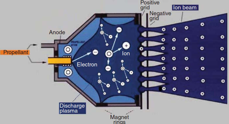
Electrons emitted by the (hollow) cathode traverse the discharge plasma and are collected by the anode; along the way they impact atoms and create ions.
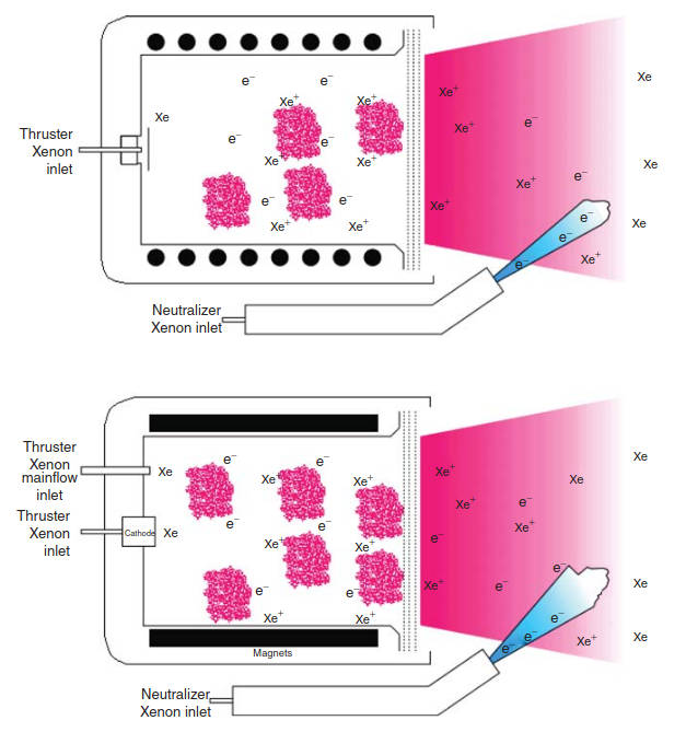
The magnetic field inside the chamber enhances the ionization process and its efficiency. As they exit the engine the ions are electrostatically accelerated. In an ion thruster, the propellant (Xenon) atoms are ionized in a discharge chamber (anode). An electrostatic field is then used to accelerate the positive ions to produce the required thrust. To prevent the spacecraft from charging, the positive ion beam must be neutralized by an equivalent negative charge. NASA has developed a Deep Space One Ion Engine, the NASA’s Evolutionary Xenon Thruster (NEXT).
Hall Effect Thrusters
The Hall Effect Thruster (HET) makes use of the Hall Effect (discovered in the 1870s by Edwin Hall). The Hall Effect is the production of a voltage difference across an electrical conductor, orthogonal to an electric current in the conductor and a magnetic field perpendicular to the current; an electric force Fe is generated orthogonal to the direction of conventional electric current from charge buildup; and a magnetic force Fm is generated on the negative charge buildup.
Electromagnets are used to generate magnetic fields. The Hall Effect confines electrons: these electrons impact the propelled fuel’s atoms to create ions. Hall thrusters provide high specific impulse (compared to chemical thrusters) and high thrust-to-power ratio (compared to ion thrusters). One example is NASA’s High Voltage Hall Accelerator (HiVHAC) Thruster. See Figure 6.
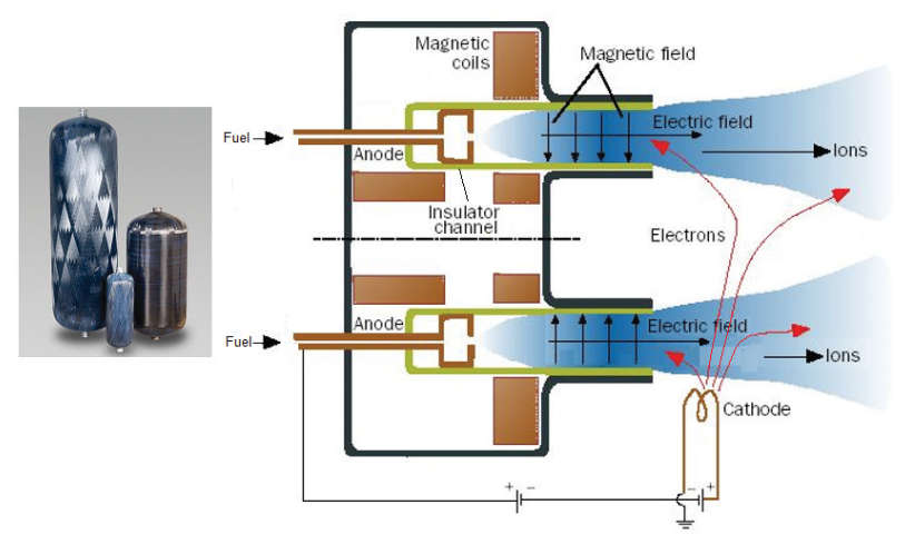
MagnetoPlasma Dynamic Thruster
The MagnetoPlasma Dynamic Thruster (MPDT) is proposed by the EP and Plasma Dynamics Lab of Princeton University. MPDT entails an ionization step, an energizing step, an acceleration step, and a detachment step. Superconducting magnets generate a magnetic field where the fuel gas is transformed into a cold plasma (by a plasma source antenna); a Radio Frequency (RF) booster antenna energizes the plasma and accelerates it, then, it is ejected.
The actual working of magneto-electric thrusters is relatively complex. Charged particles are set in motion – in opposite directions – by the electric field. A magnetic field has an effect on a moving charge known as the “Lorentz force,” similar to that which an electric field has on a stationary charge: it pulls the charged and moving particle sideways. By combining the effects of the electric and magnetic fields, the flow of charged particles is accelerated and ejected by the thrusters, producing the desired push. See Figure 7.
Advantages and Disadvantages of All-EP
All-EP (or even hybrid EP) offers several advantages, including:
- Electric-propulsion engines are more efficient than chemical ones: they require significantly less propellant to produce the same overall effect, for example a specific increase in spacecraft velocity. The propellant is ejected up to 20 times faster than from chemically-based thrusters and, thus, the same propelling force is obtained with a lot less propellant. An all-EP spacecraft utilizes fuel very efficiently: a bi-propellant system may weigh four metric tons to do the same type of activity that a two metric ton EP would do (the xenon ion propulsion system is 10 times more efficient than chemical thrusters).
- The total mass of the satellite is approximately half of what a traditional chemical propulsion satellite system would be. For many missions, launch costs range between one-fourth and one-half of total mission costs; hence, reducing these costs can have a major impact on the overall return on investment. EP’s ability to reduce or eliminate the weight of a satellite’s chemical propulsion fuel and hardware allows operators to select a less-costly launch vehicle or make more efficient use of a given launch vehicle’s capability.
- Because of lower mass operators may employ a dual launch configuration (e. g., on the newer SpaceX Falcon 9 rocket), reducing launch cost; without the mass burden of large fuel tanks, satellite operators have the option of tailoring their spacecraft to be more lightweight, allowing the satellites to be launched on smaller rockets or in tandem to spread launch costs between two missions. Launching two all-electric telecom payloads on a Falcon 9 rocket puts launch costs for each satellite at about $30 million (as of press time).
- All-EP satellites will improve capital investment efficiencies and are likely to expand business opportunities.
- While all-electric spacecraft will require longer orbit raising intervals, operators may be able offset the longer time frames with shorter production cycles.
- All-electric satellites can also carry larger payloads: because of the efficiencies of EP, larger payloads can fit on a smaller platform.
- Electric thrusters provide the ability to regulate the force applied to the spacecraft very accurately, making it possible to control the spacecraft’s position and orientation along its orbit with improved precision.
- Once the satellite is in orbit, during the execution of a maneuver in the stationary orbit, one will have a better pointing accuracy toward the earth; signal variations will be reduced; instead of doing one station-keeping maneuver every two weeks, operators will be doing one maneuver every day.
- By offering a dual launch configuration, more easily achieved in all-EP-based spacecraft, the financial cost and risk is cut in half for operators, which lowers barrier-to-entry into the space market for small providers and entrepreneurs.
- EP is safer, as it involves smaller amounts of flammable fuels during the spacecraft preparation for launch.
- The force EP produces can be applied continuously for very long periods – months or even years.
- Further improvements in satellites’ propulsion and power systems may support an increase their service life to 20–30 years from the current 10–15 years.
- While the benefits of using EP for station-keeping have been significant, traditional chemical propulsion systems are still the main workhorses for more heavy-duty in-space propulsion tasks such as orbit-insertion. As early as 1999, satellite manufacturers saw success with EP “orbit-topping.” In orbit-topping, chemical propulsion provides the first series of orbit-raising maneuvers and afterward the orbit-raising campaign is completed using EP. Satellites that use EP for orbit-topping are said to have “hybrid” chemical/EP systems. The benefits of using EP for orbit-topping are the same as those for station-keeping, but with even greater financial and operational payoff.
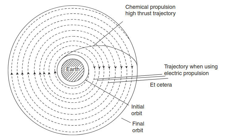
EP also has disadvantages, including, but not limited to the following. As we have seen, chemical engines can eject large amounts of propellant, while electric thrusters produce very small flows; in turn, this implies that it takes much longer to achieve a particular speed and when high acceleration is a requirement, electrical propulsion cannot be employed with the current-generation technologies. It takes up to eight months to move a satellites from temporary transfer orbit to their final operating GSO slot. (The US Air Force and Lockheed Martin achieved an inadvertent demonstration of all-electric orbit-raising in 2010 and 2011 following a mishap with the primary chemical propulsion system on an Advanced EHF strategic communications satellite – the AEHF 1 spacecraft reached its operational orbit nine months after launch). See Figure 8.
Because the thrust of EP systems is lower than with chemical propulsion systems, as noted, it will take satellites up to 6 months longer to reach their final GSO orbit compared with systems with chemical or hybrid engines. This not only exposes the spacecraft to increased exposure risk, but also reduces the amount of time the spacecraft is able to generate revenues (in a true sense delaying market entry). Typically operators want to raise through the Earth’s radiation belt in a rapid manner. The Van Allen Belt contains trapped high-energy particles captured by the earth’s magnetic field; the Van Allen Belt exists in a middle-level zone located below the GSO and above the Low Earth Orbit (LEO). The radiation degrades the solar cells a little bit each time they pass through. Spacecraft with all-EP may ultimately require adding more shields, which in turn adds mass and reduces the size of payload, minimizing one of the system’s key advantages.
Some practitioners are still reluctant to endorse all-electric satellites because these designs introduce new failure modes on the spacecraft: if one eliminates the chemical system completely, one has some new risks; for example, as the satellite separates from the launch vehicle, the spacecraft can also tumble out of control due to an anomaly – in this situation EP will not easily be able to correct the spacecraft if that occurs – chemical thrusters would be able to handle that situation better. Thus, according to these practitioners, an “all-EP” spacecraft would use newer, not fully-space-tested technology, as an aggregate system, where the technology risk is not fully retired.
Read also: Empowering Global Communication with INMARSAT Satellites in shipping
Station-keeping maneuvers can be supported, but orbit raising, drifts, and BIUs may not be as efficient as with traditional propulsion. An orbital drift maneuver with chemical propulsion achieves a movement of 1,25–1,75° a day – a drift of 180° may take 3-to-4 months; with EP this drift may take longer, also impacting revenues.
Some have raised issues related to the interaction between the plasma plume of an ion engine and the spacecraft. Generally, the phenomenon of surface degradation (erosion and sputtered particles re-deposition) is clearly identified as potential interaction that can degrade the spacecraft’s structure.
Basics about Station-Keeping
Spacecraft in GSO (and other orbits) gradually drift north–south on a daily basis due to the influence of the sun and moon. There is a gradual increase in the inclination of the orbit. If left alone, a satellite that has initial zero inclination will have its inclination increase at the rate of 0,8° per year; a GSO spacecraft moves through space at 6 878 mph. It is usual not to let the maximum north–south movements exceed ±0,05° to allow the use of large numbers of fixed pointing moderate sized antennas.
Typically, a GSO box is around 0,1° of longitude which is approximately 70 km (43,5 miles) in length.
Slightly different boxes are used by some operators.
Rec. ITU-R S.484-3 1 Recommendation, “Station-keeping in longitude of geostationary satellites in the fixed-satellite service (1974-1978-1982-1992)” states that “ … space stations on geostationary satellites using frequency bands allocated to the fixed-satellite service should maintain their positions within ±0,1° of longitude of their nominal positions irrespective of the cause of variation … ”. The recommendation also makes these observations.
A satellite is ideally geostationary if its orbital elements satisfy the following conditions:
- Semi-major axis a = synchronous radius = 42 165 km;
- Eccentricity e = 0;
- Inclination i = 0.
The orbit gradually departs from the geostationary state, however, due to the perturbation forces acting on the satellite. The distortion of the earth’s gravitational field due to the non-sphericity of the Earth causes either a steady increase or decrease in the semi-major axis, according to the stationary longitude of the satellite. No change however occurs at four special longitudes called the equilibrium points. When the semi-major axis deviates from the synchronous radius by Δa (km) the satellite longitude drifts at the rate of -0,013 Δa degrees per day. The solar radiation pressure, acting in proportion to the ratio of satellite cross section to mass, changes the eccentricity with time. There is also a minor effect due to the Moons gravity. A non-zero eccentricity e yields a diurnal libration motion in the satellite longitude of as much as ±2e×180/π degrees. The gravity of the moon and the sun acting as a tidal force on the satellite changes the inclination at a rate that varies from year to year between 0,75 and 0,95 per year. A non-zero inclination i (degrees) yields a half-diurnal longitudinal libration motion of as much as ±(i2/4)(π/180) degrees. This becomes significant for longitudinal station-keeping when the inclination is greater than a few degrees.
The “operational box” is ±0,05° horizontally and vertically from the location the spacecraft is allowed to operate in (also known as east/west and north/south travel or station-keeping). See Figure 9.
In some situations, a satellite operator might be locating multiple satellites within the same slot, this grouping being called a cluster. Clustering allows more satellites to be located at an orbital slot, always within the established box corresponding with that orbital location, but they give rise to challenges for keeping the individual satellites separated. Clusters are used such that a Direct to Home (DTH) antenna pointing at a given orbital location will see multiple satellites, each perhaps supporting (say) four transponders, so that each spacecraft can use more of its available power just for those transponders (a cluster of 6 spacecraft would cover the entire 24 transponders).
Spacecraft have a specified amount of rocket fuel that is used periodically (every few weeks) to correct the trend toward orbit inclination increase. Typically a brief burst firing of the north–south thrusters will be made as the satellite crosses up across the equator, so that instead of continuing gradually upwards it instead goes gradually downwards, effectively into negative inclination. The inclination then reduces over the next few weeks to zero and then increases again, by which time another thruster firing is needed. The net result is that over a period of 10–15 years the station-keeping fuel is gradually used up, but for this entire period the satellite is maintained within ±0,05° north–south of the equator. A small proportion of the total fuel is used for east–west orbit adjustments, since there is a tendency for satellite to very slowly drift sideways due to the triaxial nature of the earth (gravity is slightly stronger at three points around the equator).
Once a satellite is getting near the end if its normal north–south station-keeping the satellite operators decide to stop and concentrate the remaining fuel on the much more economic east–west station-keeping, so as to extend the life by several more years. During this period the satellite is kept in its east–west position so that interference to adjacent satellites is avoided, but its inclination is allowed to increase to, say, ±5° over a half-a-dozen years. The communications payload continues to operate, with some loss of performance at the edges of the coverage beams since they no longer always point accurately at the countries on the ground all of the time. During the inclined orbit years earth stations must have tracking antennas so that their pointing is adjusted to aim at the satellite all during the day; the beam pointing movement is a lissajous “figure of 8”, but at times it might be a tall slim elliptical shape or tilted elliptical shape.
The thrust required for the different space missions falls into the ranges: 200–400 N for elliptic-circular orbit transfer, 80–100 mN for station keeping of a GSO satellite and a few micro-N for precise positioning of scientific probes. The thrust T is defined as the product of the mass flow rate by the exhaust velocity of the propellant. Thrust is not the only parameter that needs to be taken into account when choosing the best thruster: another significant parameter is the specific impulse (Isp) defined as the ratio of the thrust to the mass flow to the intensity of gravity at the surface of earth. The specific impulse is related to the mass consumption for a defined mission associated to a required velocity variation of the spacecraft. A high specific impulse allows for a decrease in the mass of propellant and, consequently, a decrease in the mass of the satellite or, for the same mass, having more on-board electronics; as a tradeoff, a higher thrust allows a faster change of orbit. The main parameters of concern are:
- Axial thrust;
- Specific impulse;
- Mass consumption;
- Power per mN;
- Efficiency.
Station-keeping maneuvers include:
- East–west maneuvers;
- Drift and eccentricity maneuvers;
- Inclination maneuvers;
- Momentum adjustments.
East–west maneuvers are achieved with a single-part thruster firing, using thrusters on either the east or west side of spacecraft; the maneuver adjusts satellite longitudinal drift to remain within defined limits. During these maneuvers one should plan to minimize eccentricity magnitude to the extent possible and to minimize fuel use. Both the earth and the spacecraft are rotating/revolving in an easterly direction. Since the spacecraft is drifting west, we can think of the earth moving (rotating) underneath it, but faster than the satellite is revolving in its orbit above. Therefore, the spacecraft needs to move faster (more eastward motion) in its orbit. The spacecraft’s velocity can be increased by reducing the size of the semi-major axis (SMA) of its orbit. The SMA is reduced by firing east. This imparts a negative delta-V. Doing so at perigee yields a negative delta-eccentricity, which also reduces its daily longitude excursions.
Drift and eccentricity (D&E) maneuvers entail two large east–west maneuvers having additive effect on eccentricity in inertial space, while effectively canceling their longitudinal and drift effects in an earth reference. These are used to correct for solar radiation pressure (this being greater on larger spacecraft and on those with larger surface areas), and triaxiality.
Inclination maneuvers are needed routinely, as noted above. Out-of-plane gravitational torque effects from sun and moon “pull” the angular momentum vector toward the Vernal Equinox. Viewed from the equinoctal plane, the inclination vector moves toward Summer Solstice. Lunar gravitation causes cyclic variation and solar gravitation causes regression of moon’s line of nodes (the Kamel/Tibbitts cycle).
Momentum adjustment maneuvers (momentum management) are performed entirely by thrusters. Inertial attitude is updated using earth sensor and sun sensor data.
Industry Approaches
EP-equipped satellites (all-EP, and station-keeping EP) are likely to be increasingly utilized because of the benefits of saving fuel, launch mass reduction, extended life, and larger payloads. Hybrid spacecraft will continue to see deployment and “all-EP” systems are now being deployed. Observers argue that depending upon how expensive or complicated the mission is, large operators plan on taking advantage of all technologies (all-electric, all-chemical, and hybrids); while no operator might be willing to test an all-electric system on a large $250 million satellite, some would take a chance with a smaller 10-kilowatt satellite.
All-EP proponents make the following assertions:
- EP technology offers potentially disruptive cost savings that have implications across the satellite value chain;
- Over the next 3–5 years (2019), use of EP for satellite orbit-insertion is likely to see rapid growth;
- Expanded use of EP will offer satellite operators the opportunity to reduce mission costs and increase revenue, but will also present challenging strategic questions.
In 2012 Satmex (recently acquired by Eutelsat) and Asia Broadcast Satellite (ABS) each ordered satellites with all-EP from Boeing. Also in 2013, an unnamed US government customer ordered three light-class geostationary satellites from Boeing. Boeing’s 702SP (small platform) design uses EP to perform all of its orbit-raising maneuvers; the spacecraft has a dry mass percentage of 80 %, far higher than typical industry ranges of 40–60 %. That high dry mass ratio will enable the lightweight 702 SP to dual-launch onboard a Falcon 9 v1.1 without sacrificing payload capability (thereby cutting launch costs nearly in half). The Boeing 702SP platform is a smaller version of Boeing’s 702 satellite bus used by commercial and military operators. With the introduction of the Boeing 702 SP, Boeing has done away with chemical propulsion altogether. When launched in 2015, the 702 SP will be the first commercial spacecraft designed to use EP for the full orbit-raising campaign. According to observers, the mission and financial parameters of the Satmex/ABS spacecraft – which would be impossible without EP technology – “sent shockwaves through the global commercial space industry … several major operators [now] indicated they expected to be purchasing their own all-electric satellites in the near future … likewise several satellite manufacturers stated that they would soon introduce their own designs for an all-EP satellite.”. The first two Boeing 702SP satellites, ABS 3A and Satmex 7, will launch in early 2015 in a dual-launch aboard a SpaceX Falcon 9 rocket; ABS 2A and Satmex 9 were expected to launch on another Falcon 9 booster later in 2015. Each of the ABS and Satmex satellites will have a launch mass of less than 4 000 lb but still offer communications throughput and power comparable to larger classic satellites with conventional fuel.
The Boeing 702 thruster is a xenon ion propulsion system (XIPS) and is the culmination of nearly four decades of research into the use of EP at Boeing. Boeing’s 702SP satellite has a capability of 7,5 kilowatts of payload but the mass of the satellite is effectively half of what a traditional satellite system because it does not carry chemical liquid fuel tanks (many other satellites with that power range are up to 2 000 lb heavier at launch than the Boeing 702SP). The propulsion system works by accelerating electrically-ionized xenon gas through a thrust chamber at more than 60 000 mph; the thrust of an ion engine is lower than chemical propulsion, but the engines can fire for thousands of hours and consume less propellant. Boeing also redesigned its 702HP (high power), which uses both electric and bipropellant fuel to provide a configuration compatible with the Falcon 9, and introduced the 702MP (medium power) in 2009, which uses bipropellant but was designed to also accommodate other, more efficient EP.
As of press time, only three major commercial satellite manufacturers were offering GSO communications satellites that use EP for the full orbit-raising campaign, while at least five manufacturers were offering hybrid chemical/EP satellites. Lockheed Martin Commercial Space Systems had not decided to produce an all-electric satellite as of press time, despite its success with the AEHF 1 satellite’s orbit-raising. The firm has electrical propulsion technology, but not at a commercial-operator price point. Lockheed’s standard offering has been its A2100 product since 1996, which uses arc jets that enhance the capability of chemical propulsion systems; the company reportedly expects to continue HCTs as standard equipment. (HCTs provide more thrust than most other EP systems – as noted they utilize magnetic fields to focus and accelerate ions while traditional ion engines use electric fields to accelerate ions.) Space Systems/Loral was reportedly developing an ion thruster system to shorten the orbit-raising period to as low as three months for availability in 2015.
Approximately one quarter of the spacecraft in the Intelsat fleet use a mixture of electrical and chemical propulsion systems, while the rest rely on chemical propulsion systems; the EP technology uses can be XIPS, arc jets and, since 2000, a Russian-developed ion propulsion system called SPT. None of the spacecraft use an all-EP system.
As an illustrative example of engine subcomponents, Space Power, Inc. part of Pratt & Whitney Space Propulsion, offers fully integrated propulsion systems that include HTCs, Power Processing Units, propellant management systems, tanks and other components. The press time family of HTCs is shown in Table 4.
| Table 1. Examples of hall effect thrusters. Courtesy: Space Power, Inc. / Pratt & Whitney Space Propulsion. | ||
|---|---|---|
| T-40 |  | The T-40 Hall Effect Thruster is an ideal size for orbit adjustment for small satellites and east–west station keeping for large satellite systems. The T-40 operates at 0,1–0,4 kW and produces 5–20 mN of thrust with specific impulse values varying between 1 000 and 1 600 s, depending on operational conditions. The T-40 has undergone successful demonstration testing at the Air Force Research Laboratory and is currently being prepared for complete system qualification testing. |
| T-140 |  | The T-140 Hall Effect Thruster is an ideal size for north-south station keeping for large satellites. The T-140 operates at 1,8-4,5 kW and produces 160–300 mN of thrust with specific impulse values varying between 1 800 and 2 200 s, depending on operational conditions. This system has undergone successful demonstration testing and is currently under evaluation for complete system qualification testing. |
| T-220 and T-220T |  | The largest Hall Effect Thruster in the family is the T-220. The first version of this engine was tested at NASA Glenn Research Center (GRC). Since that time Pratt & Whitney has developed a high-power, high-thrust version designated as T-220HT. The T-220HT is an ideal size for orbit insertion and orbit transfer of large satellite systems. The T-220 or T-220HT can also be configured to operate in a dual mode: low specific impulse-high thrust for orbit insertion/transfer and high specific impulse-low thrust for station keeping. The T-220 thrusters operate at 7–20 kW and produce 0,5–1,0 N of thrust with specific impulse values varying between 1 500 and 2 500 s, depending on operational conditions. The T-220 has undergone successful demonstration testing at NASA GRC for 1 000 h and demonstrated about 2 500 s of specific impulse with very low material erosion. The T-220HT has undergone extensive performance mapping under orbit transfer conditions at NASA GRC. The profile of the exhaust plume and radiated electromagnetic noise have also been measured. The results show that the T-220HT has a very narrow exhaust plume and it is electromagnetically very quiet. |
New Approaches and Players for Launch Platforms
Delivery of payload in space, including into the GSO, still remains an expensive and often delay-prone proposition. Depending on the size and weight of payload, the cost of a single launch ranges from $100M to 250M, with commercial GSO-class satellites being at the lower end of that range.
Until early 2014, most commercial operations used Russia’s space agency in Kazakhstan or Europe’s Space Agency, which launches from French Guiana.
Space Exploration Technologies Corporation (SpaceX)
SpaceX is a new commercial entrant that recently charged only $55 M for the launch of a GSO-class satellite. They use some new technologies to reduce costs. Whether these figures are the target point or whether this was an incentivized first-GSO launch price listing remains to be fully determined. SpaceX officials have reportedly targeted a $60 million typical price tag for such a launch; industry observers, however, expect SpaceX’s prices eventually will climb to about $100 million per launch. Nonetheless, the entry of SpaceX will bring competition to the effective duopoly for commercial launches that existed. SpaceX’s Falcon 9 rocket has a modular design and reusable elements. The upgraded version of the Falcon 9 rocket can launch up to 10 000 lb (4 500 kg) to geostationary transfer orbit; the Falcon 9 rocket lifts less mass than of its major competitors, but it is also less expensive. SpaceX’s strategy is to attract customers with lower prices and with a more expedited launch schedule than the incumbents. The company already had a $4 billion book of business at press time.
One of the most expensive factors impacting launch economics is that the rocket typically burns up in the atmosphere when it returns to earth or is lost to the ocean. That is the reason Grasshopper, the company’s prototype for a reusable Falcon 9 rocket, is very promising. The cost of the Falcon 9 rocket is $55 million and it utilizes $200 000 worth of fuel. Hence, in principle, one wants to get to a situation where the rocket is actually reusable, and the only costs to launch a satellite are then the fuel, the refurbishing rocket costs, and the ground support services; that would reduce the launch costs considerably.
Sea Launch
Sea Launch provides heavy lift launch services based on the Zenit-3SL launch system. The company has gone through several reorganizations and some lauch failures. In May 2014 they successfully launched Eutelsat 3B. The Sea Launch Zenit rocket blasts off from a mobile platform on the equator in the Pacific Ocean. Sea Launch’s Zenit rocket is available for missions with single payloads of more than 6 metric tons.
Under leadership from Energia, the organization has completely restructured the contracting for the Zenit-3SL supply chain, streamlined the oversight of all Russian contracts for hardware and services, introduced a new level of transparency in conducting customer audits and obtained performance guarantees from key suppliers.
Traditional Launchers
The key traditional satellite launchers include:
- Arianespace. The firm utilizes the Ariane 5 rocket; the rocket is tailored for tandem launches of satellites weighing six metric tons total or individually three metric tons. The Ariane 5 launch base is in French Guiana, just north of the equator. Equatorial launches are beneficial for geostationary orbiting satellites because they require less powerful rockets and less liquid propellant to reach a spacecraft’s final station (there is a mass penalty for satellites launching from higher inclinations: the spacecraft must fly aboard a larger launcher or carry more fuel in its tanks to make up the difference and reach its ultimate destination in space).
- International Launch Services (ILS). The Proton rocket and Breeze M upper stage can support single or dual launches with a total payload up more than six metric tons. In 1995, International Launch Services was established, upon the merger of Lockheed and Martin Marietta companies, to market Proton and Atlas launch services to the commercial satellite telecommunications marketplace worldwide. Prior to the merger, each of these companies were competing in the commercial launch services market with the Proton and Atlas rockets. With a history of demonstrated performance, the Proton launcher provides proven on-time reliability and expanded commercial capability, launched from the dedicated world-class facilities in Baikonur, Kazakhstan. Built by the Khrunichev State Research and Production Center, the Proton rocket is the largest Russian launch vehicle in operational service. Proton launches both geostationary and interplanetary missions, and is the principal workhorse of the Russian space program. Up to press time the partnership accounts for launching 30 % of the global commercial space market. Some recent launches include:
- KazSat-3/Luch-5 V – April 28, 2014.
- Express AT1/AT2 – March 16, 2014.
- TURKSAT-4A – February 14, 2014.
- Express-AM5 – December 26, 2013.
- Understanding Inmarsat SafetyNET: A Vital Tool for Maritime SafetyInmarsat-5 F1 – December 8, 2013.
- Federal – November 12, 2013.
- Sirius FM-6 – October 26, 2013.
- ASTRA 2E – September 30, 2013.
- GLONASS – July 2, 2013.
- SES-6 – June 3, 2013.
- Eutelsat 3D – May 14, 2013.
- Anik G1 – April 16, 2013.
- Satmex_8 – March 27, 2013.
- Yamal 402 – December 8, 2012.
- EchoStar XVI – November 21, 2012.
- Yamal 300 K/Luch 5B – November 3, 2012.
- Intelsat 23 – October 14, 2012 (ILS).
- Telkom3/Express MD2 – August 7, 2012.
- SES-5 – July 10, 2012.
- Nimiq 6 – May 18, 2012.
- China’s Long March 3C launcher has a lift capacity of 5 500 kg to geostationary transfer orbit.

- G. Allen, R. Dalby, et al., “Satellite Electric Propulsion: Key Questions for Satellite Operators and their Suppliers”, Avascent White Paper, March 21, 2013. Avascent, 1615 L Street, NW, Suite 120, Washington, DC 20036.
- S. Brosse, O. Chanrion, V. Perrin, “Electric Effects OF Plasma Propulsion On Satellites”, Spacecraft Charging Technology, Proceedings of the Seventh International Conference held 23–27 April, 2001 at ESTEC, Noordwijk, the Netherlands. Edited by R.A. Harris, European Space Agency, ESA SP-476, 2001. p. 139.
- S. Clark, “Boeing Reveals Government’s All-Electric Satellite Purchase” Spaceflight Now, March 12, 2014.
- S. Clark, “Electric Propulsion Could Launch New Commercial Trend” Spaceflight Now, March 19, 2014.
- Telecom Update, Deloitte Corporate Finance LLC, Jun 30, 2013 (also, referencing Capital IQ/Thomson Financial).
- M. Dudeck, F. Doveil, N. Arcis, S. Zurbach, “Plasma Propulsion For Geostationary Satellites And Interplanetary Spacecraft”, 15th International Conference on Plasma Physics and Applications, 1–4 July 2010, Iasi, Romania. Romanian Journal of Physics, Vol. 56, Supplement, P. 3–14, Bucharest, 2011.
- Electric Propulsion White Paper, July 2002, European Space Agency (ESA).
- D. Green, The ‘total cost of ownership’, Satellite Manufacturing Special – LMCSS (Lockheed Martin Commercial Space System), July/August 2004, pages 36–39. Reporting on a 2003 Futron study entitled ‘GEO Commercial Satellite Bus Operations: A Comparative Analysis, 2003’.
- D. M. Goebel, I. Katz, Fundamentals of Electric Propulsion: Ion and Hall Thrusters, Wiley, 2008.
- R. G. Jahn, E. Y. Choueiri, “Electric Propulsion”, Encyclopedia of Physical Science and Technology, Third Edition, Volume 5, Academic Press, 2002.
- C. Patton, “All Electric Satellites: Revolution or Evolution?” Via Satellite, May 1, 2013.
- M. Prado, “Electric Propulsion for Inter-Orbital Vehicles”.
- Inclined orbit operation of geostationary satellites, November 20, 2013.
- P. B. de Selding, “Rising Transponder Prices Mask Regional Disparity”, Space News, August 23, 2012
- A. Damodaran, “Operating and Net Margins”, New York University Stern School of Business.