Explore the essential role of loading arms (hard-arms) in maritime operations. This guide covers hydraulic analysis, specifications, handling procedures, training, and maintenance, with special considerations for smaller ships. Ensure safe and efficient operations with our expert insights.
The detail relating to the specification, design, operating and testing of marine hard-arms are covered elsewhere. In this regard, the recommendations given by OCIMF are considered essential by SIGTTO for all gas terminals to follow.
This section therefore deals primarily with recommendations as they relate to accidents and other incidents as found from experience or as covered in Analysis of Incidents“Appendix 1: Known Significant Accidents and Near-Miss Data (c. 1982—1994)”.
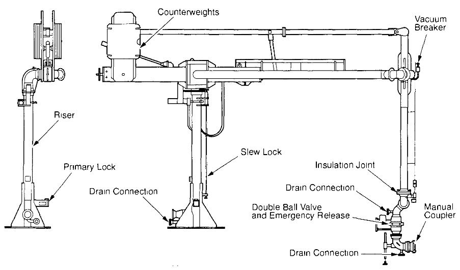
This report deals in a similar fashion with the two main types of hard-arm. There are hard-arms operated by cables and recognisable by the large cable-wheels fitted within the system. And there are hard-arms with solid linkages. By and large the former type are found in most LNG operations but the solid linkage type are familiar in the LPG trades.
Hydraulic Analysis and Surge Pressures
When a terminal is being designed the whole cargo pipeline system, including the hard-arm, should be established as being suitable for calculated surge pressures. This is discussed in Pipelines in Marine Terminals: Key Considerations for Handling Liquefied Gas“Understanding Liquefied Gas Pipelines in Marine Terminals”. For this purpose a full hydraulic analysis of the pipeline system’s required. Pipeline standards such as ANSI B 313 and B 16 5 when applied to construction, will help to ensure that the results of potentially damaging surge pressures are designed out of the system.
From an operational viewpoint, prior to Ship to Ship (STS) Preparation and Manifold Connection for Transfer Operationcargo transfer, terminal operators are responsible for agreeing appropriate procedures with ships (both operational and emergency) to limit the chance of unacceptable surge pressures. These procedures are outlined in the Ship/Shore Safety Check List. Ship/shore discussion should take into account the rate of closure of Emergency Shut-Down valves, as fitted on board and ashore, and should also take into account the provision of any surge pressure relieving devices as fitted in the shore pipeline system. For further guidance on this point see Pipelines in Marine Terminals: Key Considerations for Handling Liquefied Gas“Understanding Liquefied Gas Pipelines in Marine Terminals” From such data the maximum loading rate should be determined.
An accident report of significance (See Analysis of Incidents“Appendix 1: Known Significant Accidents and Near-Miss Data (c. 1982—1994)”) concerning a hard-arm suggests that greater attention should be paid to pressure surge phenomena and that this should be addressed at the design stage. In this respect some published guidance is available.
Hard-Arm Specification
A review of the accident information in Analysis of Incidents“Appendix 1: Known Significant Accidents and Near-Miss Data (c. 1982—1994)” shows that serious shortcomings specific to hard-arms in themselves are few – however, note should be taken of Emergency Shut-Down and Emergency Release“Emergency Shut-Down and Release Systems for Terminals” where incidents related to spill-limitation are discussed. It should be appreciated, of course, that for many liquefied gas transfers, the problems associated with hard-arms and ESD/ERC devices are inseparable. Accordingly, for most terminals Sections 6 and 7 of this document should be read together.
At the design stage (as for hoses) the proper specification of hard-arms is important as far as throughput, temperature (See Analysis of Incidents“Appendix 1: Known Significant Accidents and Near-Miss Data (c. 1982—1994)”) and pressure are concerned. However, a principal issue to be addressed relates to the arm’s physical size and reach – as covered in the next paragraph. Information on how these aspects can be best specified is found in a referenced publication.
Whilst hard-arms are in operation it is clear that, because of ship movement, they have restricted range. The limits of reach define what is known as the operating envelope and an example is shown in the diagram in this section. To ensure sufficient freedom of movement, the operating envelope must be properly specified at the time of purchase.
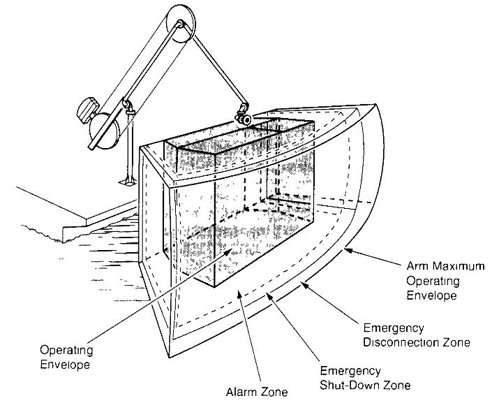
The various ship movements to be taken into account are determined by local tidal variations and ship’s draft changes whilst transferring cargo: in addition, allowances must be specified for ship movement fore and aft along the jetty and for drift away from the Jetty. Where an Emergency Release System (ERS). Is fitted the coordinates of the operating envelope help to define when the automatic start of Emergency Shut-Down (ESD) will happen and the position where, at a longer range, the automatic action of Emergency Release Coupling will take place.
Special Considerations for Smaller Ships
In following the OCIMF hard-arm recommendations it is important to note that smaller ships’ manifolds may rot always be built in accordance to appropriate ship-standards. In this regard, a question which can be encountered is described in the next paragraph. Therefore, it is good practice to physically measure local craft before deciding on the dimensions of any proposed hard-arm.
Aside from special considerations related to Emergency Release, most hard-arms are fitted with a counter-weight to balance the equipment in the empty condition. This eases power requirements when driving an arm into position. It means that, when the arm ts filled with cargo, there will usually be an additional downward force on the ship’s manifold. Sometimes this additional load has to be supported by jacks fitted to the arm but with their feet allowed to rest firmly on the ship’s deck. The larger and newer ships should be well designed in this respect (having suitable strength and space) – and references cover this aspect, however, smaller ships may have to be specially considered regarding the availability of sufficient space (between the manifold and the ship’s side) for positioning the jacks. From a ship design viewpoint, it should also be noted that ship’s working platforms may have to be suitably strengthened to carry the extra load transmitted by the jacks.
Moreover, large hard-arms when connected to small ships can Introduce forces which are beyond the strength of the ship’s manifold itself. Accordingly, but within fairly broad spectrums, the size of hard-arms must be proportional to the size of ship. In addition a need to fit manifold reducers can move the ship’s presentation flange to a position close to the edge of the operating envelope. A procedure for mitigating these problems, by connecting a large hard-arm to a small ship’s manifold with Interconnecting hose should not be allowed.
Equally, efforts by some terminals to connect large arms to smaller ships can also be misguided when multiple reducers are contemplated at the ship’s manifold. Unless properly engineered, this increases the physical lever on the ship’s structure and can cause fracture of the manifold and maloperation of ERCs (Analysis of Incidents“Appendix 1: Known Significant Accidents and Near-Miss Data (c. 1982—1994)”).
Hard-Arm Handling and Operation
Training
Hard-arms, in themselves, can be complicated. In addition they can be fitted with sophisticated ancillary equipment such as ERCs (and the attendant ERS system) Accordingly, special attention must be given to the preparation of operating procedures and the training of jetty personnel. A number of accidents are recorded in which a perceived lack of knowledge amongst jetty operators was held to blame.
Quick Connect/Disconnect Couplings (QCDC)
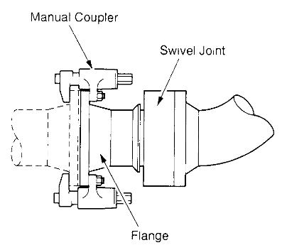
When using hard-arms, bolted flanges are often used as a means of connection to the ship’s manifold and such straightforward operations can be found in all gas trades. However, sometimes a QCDC is fitted. Its purpose is usually as an aid to speedy connection and disconnection, thus helping to reduce overall port-times. Its fitting sometimes has relevance to safety. The QCDC has no relevance for emergency release – the question of emergency release is covered in Emergency Shut-Down and Emergency Release“Emergency Shut-Down and Release Systems for Terminals”. A diagram of this type of equipment is shown below.
A safety issue where a QCDC can be of benefit is the connection and disconnection operation when the ship ts moving with the sea state. In such circumstances the manual bolting of flanges can be hazardous to operations personnel.
QCDCs may be either of the manual or hydraulic type. Because of ice formation on bare steel pipelines in the refrigerated trades, when a QCDC is to be used, it is normal to specify the hydraulic variety. This ensures ease of operation even when the manifold is completely iced over. The method used to clamp QCDCs to a ship’s manifold ts either by friction locks or mechanical (over- centre) methods. In general the mechanical method is preferred as the friction lock can work loose due to vibration and varying temperature differentials.
The operation of QCDCs has been known to cause problems (See Analysis of Incidents“Appendix 1: Known Significant Accidents and Near-Miss Data (c. 1982—1994)”). Mostly these events have resulted from Operator error Such problems have included the incomplete clamping of the coupler and activation of a release-control at the wrong time – each problem being associated with human error. There are methods now available to avoid the latter problem. One such is the provision of a lock and key The single key is the essential element and this is either inserted in the QCDC (on board ship) or in the control box (on shore) if the key is slotted into the QCDC then release ts possible if the key is fitted to the control box then activation ts impossible. And finally, the key must be slotted into the control box for cargo flow to take place.
The use of QCDCs adds an extra dimension to ship/shore operations which, it 1s recommended, should not be embarked on lightly because of design, operational and maintenance issues.
Gaskets and “O” Ring
The secure fitting of gaskets between the hard-arm and the ship’s manifold is reported as being a constant source of minor problems. Many incident reports from the LNG trade attest to this. These reports are not reproduced in Analysis of Incidents“Appendix 1: Known Significant Accidents and Near-Miss Data (c. 1982—1994)” because of their limited risks.
However, it should be noted that many terminals monitor this aspect and develop operational procedures for gasket types and replacement periods Careful monitoring of even such minor events is a feature of some trades and formalised investigation of such leaks can lead to significant improvements in the safety of operations.
Operating Procedures During Hard-arm Connection
Generally the control of hard arms, when being driven into position, is relatively straightforward and no accident reports have been received regarding this point. It is of course important for jetty operators to have a good view from the operating position so that proper control can be exercised. In some ports an elevated control station is established on a jetty structure to ensure a clear view ‘s available at all times – in yet other ports, pendant controls are used by shore operators standing on the ship’s deck. Where possible an overview of the ship’s decks from an elevated position is preferred. Control stations at jetty deck level can suffer from the drawback of the operator having to look up into the sun. At least one LNG port has automated this process See SIGTTO “Panel Papers” for 13 September 1994 – New Improvements in Loading Arms.x.
Read also: General Arrangement of LNG Custody Transfer System
One issue is of particular importance to small ships. This concerns the powering of an arm into position when the drive equipment is geared to an hydraulic system. When the arm is connected to the ship the gearing is disengaged and the arm ts allowed to free-wheel with the ship’s movements. Under the free-wheeling condition, the only force of significance placed on a ship’s manifold is the downward load mentioned in the “Hard-arm specification” and this must be within ship’s manifold design limitations.
However, for a short time, while the arm is being first connected, it may be still in-gear. At this time, if the ship is moving (because of the sea state), the force placed on the ship’s manifold can be high – the arm being held rigid by the hydraulic controls. This can be a problem, particularly for smaller gas carriers where the effects of the sea may be causing the ship to roll and pitch: even slightly.
Under these conditions undue stress may be placed on the ship’s manifold and the hard-arm itself. Clearly, hard-arms must be put into the free-wheeling mode as soon as possible and this should be carried out before bolting takes place. Some terminals are fitted with automatic means of disengaging the gearing so placing the hard-arm in free-wheel mode as soon as first connection is achieved. This can be arranged by a hydraulic plunger fitted to the hard-arm flange.
Some reports have been received on this point but they are not included in Analysis of Incidents“Appendix 1: Known Significant Accidents and Near-Miss Data (c. 1982—1994)” as no serious damage has been noted.
Hard-arm Maintenance
As suggested in “Hard-arm handling and operation”, the fitting of complicated ancillary equipment such as ERSs and QCDC couplings requires special attention to be paid to the training of maintenance personnel (See Analysis of Incidents“Appendix 1: Known Significant Accidents and Near-Miss Data (c. 1982—1994)”).
In general all manufacturers provide a schedule of maintenance requirements and this will probably require the replacement of seals in the swivel joints every five years.