Air and inert gas dryer are essential components on LNG carriers, tasked with removing moisture and impurities from the air and inert gas systems used onboard. These dryers ensure the integrity of the LNG cargo by preventing contamination and minimizing the risk of corrosion within the vessel’s gas-handling infrastructure.
Reference: SIGTTO “LNG Shipping Suggested Competency Standards”, Sections:
1 Have an awareness of their purpose and operating principles
2 Know and understand their operating parameters and limitations:
- dew point.
3 Know and understand likely problems:
- old silica problems;
- cooling systems;
- timing of purge sequences;
- symptoms of problems.
4 Know and understand operational requirements and procedures:
- setting up;
- starting;
- shut down;
- maintenance.
The drier for the air and Inert Gas – Definition and Pronunciationinert gas (IG) is normally combined in the same unit, which is usually located in the engine room.
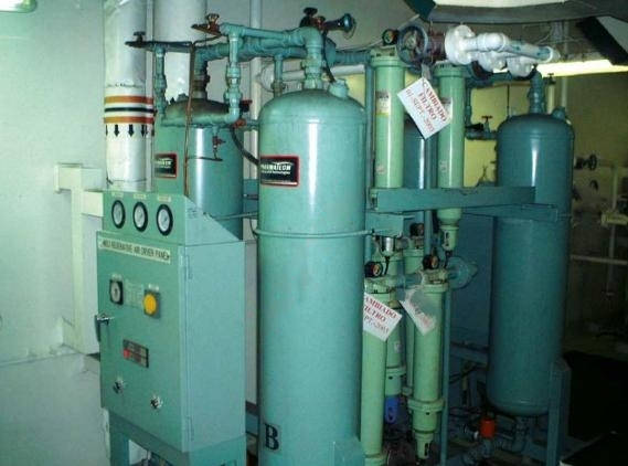
Where regenerative driers that are dependent on a supply of steam for operation are installed, alternative arrangements (such as a self-contained dehumidification unit) must be provided to allow for the production of dry air on board. This is to allow for the circumstance where the ship is in lay-up and a supply of steam is unavailable.
For driers that use a refrigerant to dry the air/IG, this must be a non-ozone depleting substance.
The dry air/IG plant conditions the dry air/IG to produce a sufficiently dry quality gas (measured by its humidity). This is used in the ship’s tank, LNG machinery and piping, for purging and gas freeing operations either prior to or after dry-dock or when tank entry is required for repair or inspection. Air driers are an integral part of the dry air/IG generating plant and should be regularly tested in accordance with the ship’s planned maintenance system.
| Typical parameters for an air/IG drier on a 174 000 m3 LNGC operating in IG mode | |
|---|---|
| Dry air delivery rate | 16 500 m3/h |
| Delivery pressure | 250 mbar |
| Dew point | The optimum dew point will vary according to the equipment installed and the parameters established in the ship’s operating manual. This is usually between minus 40 °C (-40 °C) and minus 45 °C (-45 °C). |
| Levels | O2 ≤ 0,5 % |
| CO ≤ 100 ppm vol | |
| SO2 ≤ 10 ppm vol | |
| Nox ≤ 100 ppm vol | |
| Soot = 0 Bacharach | |
The capacity of the IG generator is the same for both dry air and IG.
The demister section of the air/IG generating plant removes any water droplets and/or moisture.
Further removal of moisture occurs in the next drier stage, where the air is cooled to a temperature of approximately +5 °C by a refrigeration unit. Here, the majority of the moisture in the air is condensed out and drained off. Finally, any remaining moisture is removed by means of an absorption process in a dual vessel desiccant drier.
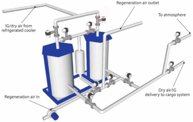
An absorption drier is designed for continuous operation and is fitted with twin absorber towers.
Dry air to the cargo tanks and pipeline system is controlled by two remotely operated control valves fitted in the distribution system. One of these is the purge valve to atmosphere and the other is the delivery valve to the Cargo containment system of gas vesselcargo system. Note, there are several types of dry air/IG systems.
| Typical parameters for a dry air/IG drier on a 135 000 m3 LNGC operating in dry air mode | Typical dry air production alarm/trip levels | ||
|---|---|---|---|
| Dry air delivery rate | 174 000 m3/h | Dew point | High setpoint minus 40 °C (-40 °C) |
| Delivery pressure | 250 mbar | Delivery line temperature | High +60 °C |
| Dry air dew point | The optimum dew point will vary according to the equipment installed and the parameters set in ship’s operating manual. This is usually between minus 40 °C (-40 °C) and minus 45 °C (-45 °C). | Delivery Press | High 270 mbar |
The dry air/IG system is located in the engine room and is connected to the cargo piping system via a removable spool piece, with blanks.
Problems may include:
- Loss of efficiency at the intermediate drying stage due to poor performance of the refrigeration plant. Typical problems associated with all refrigeration cycles may occur here, such as:
- partial loss of refrigerant;
- moisture in the refrigerant circuit;
- valve wear in multi-cylinder reciprocating compressors;
- oil carryover through the refrigerant circuit;
- lack of cooling water at the condenser;
- malfunctioning HP/LP trips.
- malfunction of one or more of the automatic drain traps, such as at the evaporator for the inter-stage refrigerant drier, demister, desiccant columns, etc. All automatic drain traps are usually fitted with a manual by-pass facility to cope with this eventuality;
- desiccant depletion as a result of:
- desiccant that has been in service too long;
- too short a time period during the regeneration phase of the drying cycle;
- inadequate supply of drying/regeneration air;
- drying/regeneration air temperature too low;
- poor combustion from an IG generator;
Note: any replacement desiccant must be as per original specification.
- malfunction or leakage past the automatic change-over valves on the desiccant columns;
- malfunctioning dew point meters, which require calibration at regular intervals to ensure accuracy.
These issues will manifest as an elevated dew point, emphasising the importance of ensuring correct calibration of the installation’s Complete Manual for Engineers about Dew Point Reservoirsdew point meter. A portable instrument should also be used to check the dew point prior to delivery to the cargo system.
If the dry air/IG plant has been shut down the driers should be regenerated, ideally two days before use.
Setting and starting up
For the production of dry air, the following applies:
- there must be no combustion in the generator;
- the O2 trip function must be overridden when the mode selector is on “dry air production”.
When the plant is running, the operator should check and record all values on the locally mounted instruments. Any abnormal values should be investigated and the fault corrected as soon as possible.
Shutdown. When shutting down, production is changed from consumer supply to “purge/vent” (delivery valve closed, purge valve opened). Shutdown can then be progressed as per the established procedures for the equipment.
Maintenance
Maintenance on the dry air production side of the plant should be covered as part of the approved planned maintenance system (PMS). Typically, this would include, but not be restricted to:
- the blowers, intermediate drying stage fridge compressor and the regenerating air circulating fan will all be monitored for condition under the approved vibration monitoring system;
- testing of all systems associated alarms/trips will be carried out according to the relevant part of the ship’s alarm test register;
- desiccant renewal as determined by the PMS frequency, which is usually based on run hours. A sample may be sent for analysis to the manufacturer. Typically, for a plant subject to moderate use, the desiccant would be renewed annually.