An LNG (liquefaction natural gas) production plant is designed to meet the production target with specifications that meet the contractual agreement (Table 1) while satisfying the emission and environmental regulations. The LNG liquefaction plant is a complex process, and for this reason, it is important to understand the design limitations and the process interaction among the different units for plant operation. The focus of this chapter is to discuss the process parameters and typical pitfalls that operators may encounter in a day-to-day operation. Note that only the major process units that are critical to the LNG plant and regasification operation are addressed in the following sections.
- Introduction
- LNG plant normal operation
- Slug catchers
- Condensate stabilization unit
- Acid gas removal unit
- Sulfur recovery unit
- Tail gas treating unit
- Molecular sieve unit
- NGL recovery unit
- Liquefaction unit
- LNG storage tanks
- General startup sequence
- Startup preparation
- Startup work plan
- Plant precommissioning
- Plant commissioning
- LNG plant startup
- LNG plant utility and offsite
- Acid gas removal unit
- Molecular sieve unit
- NGL recovery unit
- Liquefaction unit
- LNG plant shutdown
- Performance and acceptance test
- LNG regasification terminal normal operation
- LNG regasification terminal startup
- Preparation of flare
- Cooldown of unloading system
- Cooldown of storage tanks
- BOG compressor/recondenser
- LP LNG pump
- HP LNG pumps and vaporizers
- LNG regasification terminal shutdown
Introduction
The generic units such as NGL fractionation units, condensate hydrotreating unit, refrigeration unit, and nitrogen rejection unit are left to the reader. This chapter also briefly addresses the general guidelines on the startup and shutdown of the LNG plant and the regasification terminal.
LNG plant normal operation
The success of a plant operation is judged by its reliability, availability, and safety records. A high availability factor enables the plant to meet the contractual obligation to deliver the product on schedule. As such, the plant must be designed to operate under various feed gas conditions and the equipment must be designed with flexibility in mind to maintain production during equipment failure or unit turnaround. They must also be able to meet the plant turn-down or rampup requirements.
Most often, multiple units are necessary and spare capacities and design margins must be included such that when one unit is down for maintenance, the spare capacities can be applied to make up the losses. For equipment that is susceptible to mechanical fatigue and fouling such as pumps and com-pressors, plate and frame heat exchangers, and filters, they are often spared. Major equipment must be inspected and maintained regularly to meet industrial and safety standards.
A typical LNG production plant is shown in Figure 1 in “Gas Conditioning and Natural Gas Liquids Recovery Technologies“. The following discusses the various process units that must be successfully operated to maintain LNG production.
Slug catchers
Slug catcher is a critical unit that safeguards the LNG production plant against surge in flow and pressure swing from upstream oil and gas production wells. The separator serves as a three-phase separator where the gas, hydrocarbon liquids (condensate), and aqueous phase are separated.
Daily monitoring of the pipeline operation, such as pressure drop and temperatures, are necessary to ensure a stable feed to the plant. When pressure drop in the pipeline system becomes excessive, a pipeline pigging operation should be started to remove the contaminant, wax, and corrosion debris from the pipeline.
The inlet gas compositions should be analyzed daily, especially the acid gas contents and contaminant levels such as mercury and mercaptans. In most cases, these contaminants are very dilute in the gas phase, which may not be in the detectable levels. They are concentrated in the liquid phase and can typically be detected in the condensate from the slug catcher. The amount of contaminants in the vapor phase can be calculated using the liquid composition distribution and the frequency of pigging.
Condensate stabilization unit
The function of the condensate stabilization unit is to process the condensate from the slug catchers and to remove the light components to meet the export condensate specification, which is typically set at 4 ppm H2S and a RVP of 8 to 12 psi. A typical condensate stabilization unit is shown in Figure 4.
The stabilizer column operates as a stripper column. The pressure of the column is controlled by removal of the light components using a two-stage compression system. The H2S and light hydro-carbons are recycled back to the feed gas section and then to the acid gas removal unit. The column bottom product specification is controlled by heat input (steam) to the reboiler. The condensate product is cooled with a heat exchanger and product cooler and is sent to the condensate storage tanks under level control of the stabilizer column.
Although condensate can be considered a side product from the LNG production plant, the liquid production adds significant value to the facility. If the condensate contains other sulfur components such as mercaptans, it is worthwhile to be further treated to meet the sulfur specification of the condensate product.
With respect to the contaminants in the liquid hydrocarbon stream, the operation of the stabilizer shall take the following effects into consideration:
- Sulfur components. It is desirable to strip off as much H2S with the overhead gas as possible to meet the condensate specification. Preferably, the condensate should contain mercaptans only. This can be achieved by overstripping. However, this may result in sending heavier hydrocarbons to the stabilizer overhead stream and introduces a risk of hydrocarbon condensation in the AGRU with potentially foaming operational problems as a consequence;
- Water. To meet the H2S specification in the bottom product, the required bottom temperature is higher than the bubble point of water at the prevailing operating pressure, and consequently water will not be able to leave with the stabilized condensate. Water entering the stabilizer must leave the system as an overhead liquid or vapor. Water must be removed from draw trays above the feed tray or from the reflux drum. A stabilizer column will be required at the appropriate position in the stabilizer. The drawn off fluid is routed to a separator vessel, where the excess water is removed and the hydrocarbons are returned to the stabilizer column;
- Salts. Any water entering the stabilizer may contain dissolved salts. These may precipitate in the stabilizer or on the reboiler tubes. At sufficiently high temperature these salts will hydrolyze to form hydrochloric acid, which may cause material failure;
- LPG. If the condensate contains excessive LPG, the propane content may create a recycle within the unit and eventually overload the compression system. In this case the use of a feed liquid stripper installed prior to the stabilizer and the use of a refluxed stabilizer to produce an LPG stream may be necessary, as shown in Figure 5;
- Fouling from degradation. If corrosion inhibitors are injected upstream for corrosion protection, they will end up in the condensate. Check if they are thermally stable at the column bottom temperatures. If these components degrade into heavier products, fouling of the column reboiler may result.
Acid gas removal unit
The function of the acid gas removal unit (AGRU) is removal of the acid gases to meet the specifications for an LNG liquefaction plant, typically, 50 ppmv of CO2 to avoid freezing in the main exchanger and 4 ppmv H2S to meet the LNG sales specification. A typical amine process is shown in Figure 6.
The common problems with the AGRU operation are foaming and flooding problems in the absorber or stripper. Amine solution foaming is a persistent and troubling operational problem encountered in natural gas production. Solution foaming contributes to excessive solution losses, amine carryover, and reduction in treating capacity, and may result in unstable operations and off- specification product.
Failure of the AGRU to meet treated gas specifications may be contributed by one of many factors. To determine the root causes of the problem, the operator should check the followings:
- Are the contaminant levels in the feed gas high? The gas feed flowing to the AGRU may contain chemicals, such as MEG, corrosion, and hydrate inhibitors. Although the concentration in the gas may be very low, the contaminants will be absorbed by the solvent in the AGRU and build up in the circulation system. To avoid the reduction in AGRU capacity, the contaminants can be removed by a water wash column before the amine absorber. The spent water from the water wash, containing the glycol washed from the feed gas, can be recovered in the glycol regenerator;
- Is the solvent circulation rate adequate? Sample the rich amine solution loading. If greater than the design loading limit (which is corrosive), increase the solvent circulation rate. Alternatively, if the circulation rate is already at a maximum, but with a lower than design loading increase the amine strength to the maximum limit.
- Is the lean amine solution loading satisfactory? Sample the lean solution and compare to a typical operation and the process design basis. If the lean loading is abnormal, check for the following:
- Check for leaks in the lean/rich exchanger. Check the amine loading between and after the lean/rich exchanger; if there is a significant change, it may be due to exchanger leakage;
- Check the regenerator operations. If the regenerator overhead temperature is low (< 210 °F [98.9 °C]), increase the steam flow to the reboiler. If there is no change in the lean amine loading with the proper overhead temperature, the cause may be due to mechanical damage in the regenerator;
- Check the regenerator for foaming. Check for high differential pressure or erratic liquid levels. Anti-foam may be used to regain column stability until the root source of the foaming can be determined;
- Is the lean amine solution temperature too high? Check the absorber feed and solvent temperatures and compare to the process design. For most gas treating applications, as a practical maximum, the lean amine temperature should not exceed 135 °F to 140 °F (57.5 °C to 60 °C). If the solution temperature is high, check the lean amine cooler and check if the lean amine cooler bypass line is opened;
- Is the absorber operating condition different than design? Check the inlet process conditions and compare to the design basis and historical data to see if there has been a change in the operating conditions;
- Is the absorber installed properly? If the absorber has multiple feed locations, check that the top feed location is in service. A column scan of the absorber may be used to determine poor distribution in the column, which may be due to damaged trays or plugging;
- Is the filtration system operating properly? Iron sulfide is the common particulate found in most amine solutions. Additionally, particulates can enter the amine system with the feed gas or makeup water. These may include rust particles, dirt, pipe scale, and salts. Removal of particulate matters in the amine circuit can best be accomplished by continuous filtration of a slip stream of the amine solution, typically 10 % of the amine circulation. More efficient inlet gas separation and filtration system has been proven successful in reducing foaming problems. Additionally, particulate filters should be installed downstream of the carbon filter to prevent fouling from carryover of carbon fines. Carbon filtration can be used to remove surface-active contaminants such as oil and heavy hydrocarbons that contribute to foaming;
- Is the Heat Stable Salt (HSS) level acceptable? HSS precursors found in natural gas streams include well/pipeline treating chemicals and oxygen from vapor recovery systems. A few of the more common HSS anions in natural gas applications are acetate, formate, sulfate, oxalate, and thiosulfate. In some instances, HSS can be attributed to the quality of makeup water. Chlorides and sulfate are common contaminants found in amine plants that use poor quality process water. If oxygen is present, the amine can also degrade to form corrosive by-products such as bicine, glycine, and other amino acids.
There are several methods that can be used to control the level of HSS. The obvious method is bleeding a portion of the HSS contaminated amine solution from the amine system, replacing it with fresh solvent. While this operation appears simple, disposal of the contaminated amine to a wastewater system to form corrosive by-products such as is prohibited due to environmental regulations, and is not a permanent solution. Other methods of removal of the HSS include electro-dialysis reclamation, distillation reclamation, and ion exchange reclamation, which can be provided by the amine licensors or the amine suppliers.
Sulfur recovery unit
The modified Claus process is the most common sulfur recovery process used in the LNG industry because of its simplicity and large sulfur capacity. However, there is a limitation of the modified Claus process. The acid gas stream must be relatively rich in H2S and therefore in most applications, when processing dilute acid gases with contaminants such as ammonia, mercaptans, and heavy hydrocar-bons, special design and operation considerations must be made to ensure complete destruction of these contaminants that is necessary to meet the sulfur emission requirements.
In the Claus process (see Figure 12), the overall reaction is carried out in two stages. The first stage is the reaction furnace section where air is added to oxidize only one-third of the incoming H2S to SO2. The unconverted H2S then reacts with the produced SO2 to produce elemental sulfur vapor in the later stages.
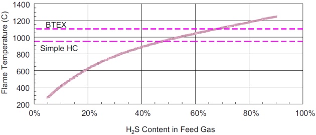
The reaction furnace is the critical piece of equipment in the Claus process. Due to the complexity of the reactions, the design and operation are more dependent on operating experience than theoretical calculations. The minimum temperature for effective operation of the reaction furnace on “clean” acid gas must be controlled at above 925 °C (1 700 °F). Below this temperature, the flame stability is poor and adverse side reactions occur, making operation difficult and unreliable. For units processing ammonia-laden sour water stripper off-gas, or feeds containing heavy hydrocarbons, BTX, and cyanide, the minimum furnace operating temperature required must be increased above 925 °C (1 700 °F) to ensure destruction of these components. Ammonia, in particular, requires a high combustion temperature, and plants with inadequate temperature are prone to shutdown from plugging due to deposition of ammonia salts. The consequence of not achieving the required destruction temperature is detrimental to the sulfur plant operation. Coke formation from cracking and incomplete reaction of heavy hydrocarbons can cause irreversible deactivation of the downstream Claus converter catalyst.
For sulfur recovery unit in an LNG plant, a straight-through process is the most common, due to its simplicity and lower costs. There are other techniques to raise the furnace temperature for ammonia destruction, such as supplemental fuel gas firing, preheating acid gas, and/or combustion air and oxygen enrichment. However, these techniques introduce a number of negative factors. Notably, there will be a decrease in overall sulfur recovery efficiency due to the formation of undesirable by-products such as COS and CS2. Oxygen enrichment requires an air separation that cannot be justified for grass root design. The equipment count is higher and the equipment sizes are larger, which increases the capital and operating cost.
In grass root design, a straight-through process is preferred, which requires the H2S concentration in the acid gas to be greater than 50 %. Figure 1 provides an operating guideline of the theoretical, adiabatic flame temperature, as a function of the H2S content in the acid gas feed. The two horizontal dashed lines provide the operator with the temperature targets, depending on the nature of the hy-drocarbons contained in the acid gas feed.
When the acid gas is too dilute in H2S, a selective absorption technique can be used to enrich the acid gas prior to entering the Claus unit. By selectively absorbing H2S from the acid gas and then stripping the rich solvent, two gas streams are produced. The gas passing through the absorber is primarily CO2. The CO2 stream can be sold as a product for enhanced oil recovery. The gas stream leaving the regenerator is acid gas enriched in H2S that can be processed in a straight-through Claus plant. The process design and configuration is described in “Gas Conditioning and Natural Gas Liquids Recovery Technologies“.
For the catalytic stages, some technology licensors, such as Fluor, employ titanium-oxide (TiO2) catalyst in one or more of the Claus converters, which greatly improves the ability to hydrolyze COS and CS2. Traditional activated alumina Claus catalyst gives high conversion of H2S, but only about 65 % hydrolysis of COS and about 30% hydrolysis of CS2 in the first Claus Converter. Conversions are reduced in subsequent Claus stages. For the second stage, activated alumina catalyst gives about 20 % hydrolysis of COS and only about 5 % hydrolysis of CS2. In contrast, even at end-of-run, TiO2 catalyst is capable of over 90 % hydrolysis of COS and CS2 in the first Claus converter when operated at proper bed temperature. Therefore the proper operation of the TiO2 catalyst enhances the overall sulfur recovery efficiency necessary to meet the environmental requirements.
Tail gas treating unit
The tail gas unit process consists of two sections, the hydrogenation section and the tail gas treating section. The hydrogenation section consists of a hydrogenation reactor, which converts the SO2 content to H2S in the presence of a catalyst and hydrogen. The hydrogenated product is cooled in a quench column by circulating with process water. The water formed in the quenching process is removed under a level control from the quench tower. The sour water is sent to the sour water stripper and then to the waste water treater prior to disposal.
The tail gas treating unit is designed to reject CO2 from the dilute acid gas using an H2S selective solvent such as MDEA. The CO2 reject stream containing ppm levels of H2S can be sent to a thermal oxidizer for disposal. The operation of the tail gas treating unit is similar to the AGRU discussed in the previous section. The solvent quality and purity must be maintained by filtration and controlling the HSS level in the solvent. The operation of the absorber and regenerator must be closely monitored. Typically the absorber is designed with several feed trays for the lean solvent; the lower feed tray is preferred as it will minimize CO2 absorption as long as H2S in the absorber overhead meets the emission limits. Typically, a lean solvent loading can be achieved with steam heating equivalent to 1.0 to 1.2 lb steam per gallon of amine circulation.
Molecular sieve unit
The dehydration unit is designed to meet the product specifications on water and mercaptans (RSH) content. The Molecular Sieve Unit (MSU) is designed to remove water to 0.1 ppmv and most mercaptans to 2 to 3 ppmv. In a natural gas plant the molecular sieve dryer is considered a reliable continuous process, characterized by a high degree of complexity and automation, and low manpower requirements. The molecular sieve unit can typically operate without interruption for 3 to 5 years with the same molecular sieves.
The molecular sieve unit feed gas is typically precooled to 40 °C or lower and condensate removed prior to entering the unit. In hot climate operation, propane refrigeration can be used to remove the bulk of its water content, which would reduce the duty of the dehydration unit.
The most significant factor affecting the performance of the molecular sieve unit is the regeneration conditions. If the unit has been producing satisfactory dewpoints but suddenly goes bad then the following items should be checked:
- Mercaptans buildup. When the molecular sieve unit is designed for dehydration and mercaptan removal, a mass balance of the different mercaptans for the regeneration gas is required. This is necessary when the AGRU is an amine base that is not capable of removal of mercaptans. The branched mercaptans that slip through the AGRU are usually not caught by the molecular sieves and are left in feed gas and fed to the NGL recovery unit. Since the lightest branched mercaptans have volatility similar to C5+, they will end up in the C5+ fraction and sent to the condensate stabilization unit. In order to perform a mass balance of the mercaptans, it is not only required to know the mercaptan concentration in the feed gas, but also the breakdown into individual mercaptans;
- Regeneration gas temperature. Check that the thermocouples are reading correctly. A low temperature shifts the equilibrium upward causing a higher than design dewpoint. Also the lower temperature results in a lower gas velocity and a slower desorption rate;
- Flow rate. Check the calibration of the flow meter. Mole sieve beds typically are designed with a regeneration flow close to laminar flow. A small change in feed condition can force the flow regime into the laminar flow regime, which is undesirable from the standpoint of heat and mass transfer operation;
- Flow channeling. Good distribution must be maintained through all of the bed to insure that there are no pockets or poorly regenerated adsorbent. Check the pressure drop during regeneration. If channeling is confirmed due to fouling then the bed should be replaced;
- Oxygen. Occasionally oxygen can get into the regeneration gas from the gas gathering system through valve seals and such. If the oxygen concentration is above 20 ppmv then there is a chance of side reactions when passing through the regeneration heater forming CO2 and water. The iron oxide coating on the furnace tubes can act as a catalyst for these oxidation reactions. The end result is that the regeneration gas is wet, which will result in off-spec gas;
- Inlet separator. The frequently underdesigned component in the mole sieve system is the inlet separator. If liquid droplets enter the beds, they can weaken the mole sieves and will cause erosion damage. On the extreme side, a massive failure can cause large slugs of liquids to hit the beds, which can crush the adsorbent;
- Bed fouling. The most common problem is fouling in the adsorber beds. If the inlet separator is not performing, liquid carryover will wet the bed rendering the mass transfer zone ineffective, which will result in an early water breakthrough. Sometimes, what is thought to be a dew point problem is actually a breakthrough problem. Amines, glycols, compressor oils, corrosion inhibitors, and heavy hydrocarbons will destroy the crystalline structure of the molecular sieves. Some of these liquids will decompose at temperatures between 200 and 350 °F resulting in coking, loss of capacity, reduction of mass transfer efficiency, and early breakthrough;
- Dehydration bed failure. This can be due to improper support screen installation resulting in buckling and loss of the mole sieve from the dehydration bed. A more sturdy support using JOHNSONSCREENS can provide more mechanical support strength;
- High pressure drop in bed. Typical molecular sieve pressure drop across the bed is approximately 0.5 bar. Higher pressure drop may indicate bed support failure, maldistribution due to clogging with aging mole sieve materials. This will cause loss of mole sieve from the dehydration bed, which subsequently ends up in the mercury removal bed resulting in high pressure drop;
- Moisture analyzer probes locations. The online moisture analyzers typically get fouled due to contact with contaminants and are prone to failure. Locating the sampling point close to the bottom of the mole sieve bed is helpful for troubleshooting and for breakthrough tests. A sampling point a few feet downstream of each dehydration bed provides a more reliable measurement of moisture contents. A sample point in the main line downstream is another useful check;
- Even distribution across the bed. Proper design of the inlet distributors is important to achieve uniform adsorption and efficient utilization of the mole sieve beds. The use of a distributor device on top of the mole sieve beds helps the mixing and distribution, avoiding the potential for bed channeling;
- Feed bypass. Check obvious sources such as leaking valves using ultrasonic leak detectors. Also look for bypasses through instrument lines or a pinhole leak in a diaphragm. Even the smallest leak can result in off spec dewpoint.
- Degradation of molecular sieve. The excessive thermal stresses of each regeneration cycle can eventually break some of the crystal bonds of the sieves. Hydrocarbons tend to decompose or crack forming coke in the macro pore structure, slowing down the adsorbing rate. An obvious way to increase the adsorbents’ life is to run longer cycles; that is, to water breakthrough stage each cycle, thus minimizing the number of regenerations and the amount of hydrocarbons on the bed;
- Change in inlet conditions. Check the inlet conditions against the design levels. Often a small change in inlet temperature can increase the water load more than would be suspected; for example a temperature rise in the inlet of 10°F might increase the water content by 40 % and result in an adsorbing time decrease of approximately 40 %. Also the adsorbent‘s capacity drops as the temperature increases. A drop in pressure will cause a proportional increase in water content and the increased velocity resulting from the lowered pressure will increase the mass transfer zone length causing an earlier breakthrough. Changes in gas composition should be monitored. If the inlet gas is coming predominantly from lean gas fields and the feed changes to a rich gas feed, more liquids will enter the plant;
- Retrograde condensation. The recent trend of operating the mole sieves system at high pressures presents a new problem. Heavy hydrocarbons may drop out due to cooling of the system due to pressure drop. This may result in wetting the adsorbent throughout the bed. Retrograde condensation is very difficult to predict but can be checked with Hysys simulation. Typically, a steadily increasing pressure drop will occur during the adsorbent cycle, which then drops back to a base level after regeneration. This is normally due to liquid accumulation in the adsorbent bed.
NGL recovery unit
The function of an NGL recovery unit is to remove the C2+ or С3+ hydrocarbons from the feed gas, producing an NGL product and a lean gas feed to the LNG plant. The operation of a high recovery NGL unit is based on the deep chilling generated by turbo expansion to produce refluxes to the NGL recovery columns. During propane recovery, the column must produce an NGL product that contains maximum 1 % volume of ethane and during ethane recovery, the NGL product must contain no more than 0.1 % volume of methane.
In order to meet the product specifications, the fractionation column must operate at a pressure well below the critical pressure of the feed stream such that reasonable separation is practical. While frac-tionation is easier at lower pressures, it will increase the refrigeration driver power consumption for LNG production. Therefore it is desirable to produce a residue gas at high pressure. One of these NGL processes is the Fluor TCHAP process. This process employs a high pressure absorber and a low pressure deethanizer for NGL production. Refer to “Gas Conditioning and Natural Gas Liquids Recovery Technologies” for detailed discussion of this process.
To achieve higher recovery, the NGL columns must be refluxed with a lean NGL. For example for high propane recovery (99 %) as shown in Figure 21 in “Gas Conditioning and Natural Gas Liquids Recovery Technologies“, both the absorber and deethanizer are refluxed with a lean ethane NGL stream produced from the deethanizer overhead. In the medium ethane recovery process as shown in Figure 22, the demethanizer column is refluxed using the feed gas as reflux. In the high ethane recovery process described in “Gas Conditioning and Natural Gas Liquids Recovery Technologies“, the demethanizer column is refluxed by recycling a slip stream of the residue gas.
To achieve high recovery while minimizing energy consumption, the reflux flow rates and the temperature profile of the process must be optimized with simulation. This also requires a close temperature approach brazed aluminum exchanger and an efficient expander compressor design. Operation of the NGL unit is very sensitive to changes in feed gas compositions and conditions and the NGL plant operating condition must be adjusted periodically for the best efficiency operation.
Some of the common problems encountered in the operation of an NGL recovery unit are sum-marized as follows:
- Feed gas composition is different than design. When processing a richer feed gas, more refrigeration is required, and the flow to the expander is lower. Conversely, when processing a leaner gas, less condensation will occur, and the vapor flow is higher. The turbo-expander may not have sufficient capacity which may require opening of the expander bypass valve. The tray loading in the upper section of the NGL column would also increase, which may result in column flooding and loss in NGL recovery;
- Column operation. One of the common problems in operating an NGL recovery unit is high pressure drop in the columns due to the formation of hydrates. Hydrates are mainly due to unsatisfactory operation of the upstream units; that is, the molecular sieve dehydration unit and the AGRU. This typically occurs during ethane recovery operation when the demethanizer is required to operate at -100 °F or lower temperatures. The high pressure drop is caused by equipment blockage by hydrates of CO2 or water, and will eventually require the unit to be placed on deriming mode. To resolve these problems, the operation of the molecular sieve unit and the AGRU must be investigated as discussed in the previous sections;
- Plate and fin exchanger. The plate and fin exchangers in the NGL recovery unit are prone to fouling by hydrate. The inlet nozzles of the exchanger are equipped with methanol injection, which can be used to dissolve the hydrates.
- Strainers. Dual parallel strainers and block valves should be installed upstream of the plate and fin heat exchangers. The pressure drop indication should be monitored and the strainer should be cleaned once the pressure drop becomes excessive;
- Turbo-expander. The turbo-expander typically is equipped with an inlet guide vane system that allows the expander to operate within a reasonable range, typically 80 to 120 % of the design flow. If the inlet flow exceeds the maximum range, the bypass valve can be opened operating on the Joule-Thomson (JT) mode. Typically, the expander control is automatic and does not require operator attention;
- Level measurements. A magnetic-type level measurement is commonly used for control purpose or local indication in cryogenic plants. The float must be specified to cover the specific gravity for the expected ranges of liquid compositions. In addition, the lower sensing line to the vessel must be properly insulated to prevent unstable level measurement due to vaporization in the sensing line;
- Dry-out lines. Dry-out line should be provided for plant startup. The exchangers, columns, pumps, and piping should be dried as much as possible. The molecular sieve unit can be used to recirculate the hot dried gas for system dry-out. If nitrogen is used for dry-out, the dry-out gas flow can be vented from the equipment to the flare system.
- Methanol injection. Residue moisture in piping and low point drains should be flushed out with methanol to avoid hydrate formation during operation. The most likely areas for hydrate formation are around the cold box, and in the demethanizer condenser. All the methanol lines should be hard-piped to the process;
- Pressure differential transmitters. Pressure drops across the plate and fin exchanger inlet strainers should be monitored to ensure the performance of the cold box. Pressure drop across the molecular sieve beds and the carbon beds should be provided with high pressure drop alarms. Excessive pressure drop in molecular sieve beds could be due to sieve material degradation contamination, or structural damage.
Liquefaction unit
The LNG production throughput is controlled by the refrigeration from the mixed refrigerant system. The operation of the mixed refrigeration train is based on controlling the MR system refrigeration output by adjusting the vapor inventory and mixed refrigerant composition. The propane system refrigeration is designed to provide cooling to the mixed refrigerant, the feed gas, and the condenser of the scrub column.
LNG production turndown is achieved by venting lighter components at the HP and MR separator. Venting the lighter components reduces the vapor inventory, which, at a constant compression ratio, causes the MR compressor suction pressure and discharge pressures to decrease. With the compressors operating at the same speed and producing the same compression ratio, the suction volumetric flow remains the same but the mass flow reduces. A decrease in mass flow through the system proportionally decreases the available refrigeration. The LNG temperature valve will throttle the LNG flow to maintain the desired LNG temperature from the main exchanger, which is the method used to control LNG production.
The propane compressor is a centrifugal constant speed machine. The discharge pressure is set by the temperature approach to the ambient air temperature in the propane condensers. The suction and side load pressures are functions of the compressor curves and the process cooling load.
During system turndown, when excess power is available from the gas turbine driver of the propane compressor, the starter motor can be operated as a generator to convert the excess power into electricity to be used by other units in the plant.
During hot summer operation, when the gas turbine power degrades, gas turbine inlet cooling should be started to maintain the power output and the liquefaction capacity. In most cases, waste heat or propane refrigeration can be used for cooling.
LNG storage tanks
The function of LNG storage tanks is to store the LNG product under a stable pressure. The operating pressure of the storage tank must stay within the design limits of the storage tank. See Table 4 in “Fundamentals of Liquefied Natural Gas” for typical storage tank operating conditions.
The flashed vapor from tank heat leak and the letdown LNG from the liquefaction plant are compressed and used as gas turbine fuel or recycled back to the liquefaction process. During ship loading the vapor return from the ship is returned to the LNG storage tanks to replenish the volume displaced by the unloaded volume. Under all conditions, the storage tank and the ship pressure must stay below the design limit. Excessive vapors produced during startup or upset are disposed of in the flare system.
In the LNG regasification terminal, tank boil-off is compressed to a higher pressure and condensed in a boil-off gas (BOG) recondenser using a slip stream of the sendout LNG. During ship unloading, the boil-off vapor is returned from the storage tank to the LNG ship to replenish the volume displaced by the unloaded volume. Under all conditions, the storage tank and the ship pressure must stay below the design limits. Excessive vapors produced during startup or upset can be recovered using the vapor condensers or disposed of in the flare system. See Appendix 3 for a detailed discussion of the flare and relief system design.
General startup sequence
A successful startup requires planning and organization and experienced and knowledgeable staff. A well-executed startup program requires a collaborated effort among contractors, licensors, equipment suppliers, and the plant owner. The startup program typically consists of the following phases.
This startup sequence is generic and can be applied to the liquefaction plant as well as the LNG receiving terminal:
- Preparation and planning;
- Precommissioning and operational testing;
- Commissioning;
- Startup and initial operation;
- Performance and acceptance test.
The contractor is responsible for planning and startup of the facility. Only when the owner is satisfied with the plant performance test results, can the contractor then turn over the plant operation to the owner.
Startup preparation
To set up the startup and planning, a startup team must be assembled together. The members can be engineers from the contractor’s home office or they can be subcontractors. Most frequently, when the plant is located in a foreign country, it is required to hire locals as much as possible, and therefore a well thought- out training program must be implemented. The success of the plant startup depends on the concerted efforts from the contractors, licensors, equipment vendors, and the plant owner. This team works together throughout the project, from startup and commissioning, to full production. All members of the team must be involved in the development of the startup procedure, including the training requirement.
Typically there is a commissioning manager or a lead commissioning engineer who will hire the commissioning team members and technical consultants. He is also responsible for training and developing safety and risk assessment, commissioning strategy, procedures, and checklist. A detailed plan and budget preparation is also prepared to be approved by the owner.
Operator training
Typically the operators are selected from the plant owner’s organization or hired from external or-ganizations. The contractor is responsible for setting up the training program for the operator who will carry out plant startup and initial operation before the plant is finally accepted. Engineers who work on the design and are familiar with the plant equipment and layout are assigned for the startup training program. Engineers from the licensor’s office should explain their system characteristics in the training class, making sure that their design is performing at the optimum design levels. Vendors of critical equipment, such as gas turbine drivers, compressors, and instrumentation systems should explain the critical design and operating parameters of their machinery.
Startup work plan
The contractor typically follows a systematic procedure whereby their startup engineers review the design drawings line by line to confirm that the plant can be started up as planned. The design is reviewed for potential startup problems such as:
- Is there sufficient capacity for surge?;
- Is the system stable and controllable?;
- Are there any hydraulic bottlenecks or water hammer problems?;
- Are there adequate high point vents and low point drains?;
- Are there sufficient dry-out lines and methanol injections?;
- Are there sufficient startup lines and bypasses for system fill, cooldown, or defrosting?
A detailed path work plan and procedures and related drawings are prepared. The work path would define the sequence of startup for each unit and system. This should also define the individual activities at each step, operational testing requirement, and cooldown procedure. The technical skills, labor, material, and equipment services are also identified.
Typical milestones for LNG plant startup are as follows:
- Utility systems;
- Offsite systems;
- Inlet facilities pressurization;
- Successful mechanical runs and testing on rotating equipment;
- Amine unit startup;
- Molecular sieve dryers startup;
- Purge and dry-out liquefaction equipment;
- Purge and dry-out LNG tanks;
- Startup of refrigeration compressors;
- Plant cooldown;
- NGL production;
- LNG production;
- Performance test and plant acceptance.
Plant precommissioning
Typical commissioning activities are listed here, roughly in chronological order. In reality, the break between precommissioning and commissioning is not hard and fast:
- As-built P&ID check;
- Safety study, prestart-up procedure review;
- Utility systems commissioned (e.g., air, steam, nitrogen, fuel gas);
- Power and lighting systems energized;
- Rotating equipment rotation check and alignment;
- Equipment internal inspection;
- Line by line punch-out and punch list;
- Installation of temporary strainers/screens;
- System pressure testing;
- Line flushing;
- Chemical cleaning;
- Line blowing;
- Instrument loop checking;
- Install packing, seals, etc.;
- Introduce Crew Evaluation Test online for seamans about Marine Lubricantslubricants, etc.;
- Load catalysts and chemicals;
- Check position of blinds;
- Assemble documentation.
The precommissioning stage verifies the integrity of the mechanical equipment by inspection, pressure testing, cleaning and flushing, and machinery checkout. The equipment is checked against specifications based on datasheets, as-built P&IDs, plot plan, layout, and piping isometrics.
For a typical plant checkout, master sets of piping drawings and P&IDs are located in a common area such that designated engineers can walk every line and verify every item as shown on the master drawings. Different color highlighter can be used to identify the system and services. The engineers must check that pipe sizes and ratings are correct, vessel nozzles and valves are correctly installed, vents and drains are in the right place, blind flanges and swing blinds are properly installed. Prepare a punch list for nonconforming items, and identify necessary corrections.
Piping inspection includes checking for piping stress from expansion and contraction due to temperature changes, alignment between flanges on pipe work, and alignment between piping and equipment nozzles. Checking can be by visual inspection and by gauge measurement. Check for thermal growth on piping supports, any surface buckling or crimping, and expansion joints.
Vessel and column inspection includes verifying trays, packing, vessel internals, distributors, demisters, downcomer, vortex breaker, and material of construction. Confirm all column internals have not been damaged during installation.
Pressure test inspection of equipment includes leak tests and verification of the design pressure to meet specifications and applicable codes and standards. Pressure testing must be witnessed by the startup team, who must verify all necessary safety limits.
Electrical system check includes verification of circuit breakers, switches, bus bars, grounding systems of equipment, explosion proof equipment and enclosure, motor control centers, transformers, switch gears, motor starters, and so on.
Equipment cleaning is the last step to ensure no construction debris is left in pipes or vessels. All debris must be removed and flushed out with chloride-free water. Chemical clean may be used if necessary. Before flushing for cleaning, check that startup screens and blinds are properly installed; jumper spool pieces should be added if necessary for startup.
Plant commissioning
Commissioning of the LNG production plant can be started when the equipment and piping system have been checked and verified, and basically consists of the following steps:
- Close-up equipment;
- Dry-out;
- Heater dry-out;
- Rotating equipment run-in;
- Purge plant with nitrogen;
- Cool-down;
- Ready for start-up.
LNG plant startup
The following is a general guideline for the startup for an LNG production plant. A generic C3MCR liquefaction train process flow diagram is shown in Figure 2. Startup of other liquefaction technologies may be slightly different.

LNG plant utility and offsite
Prior to the LNG process plant startup, the utility and offsite systems must be checked to be operational including:
- The flare system;
- The fuel gas system;
- Nitrogen system;
- Firefighting system;
- Electric power supply;
- Cooling water system;
- The heat transfer fluid system or waste heat recovery system.
Acid gas removal unit
The startup sequenced for initial operation of the acid gas removal unit is as follows.
Heat medium system
- Establish heat medium circulation;
- Blanket the heat medium surge drum with nitrogen;
- Start the heat medium heater using startup fuel gas, gradually heating up the heater to the desirable temperature;
- Charge the heat medium to the amine reboiler.
The amine system
- Add the amine solution and start circulation;
- Charge the heat medium gradually to the reboiler, taking caution of the thermal stress;
- Start the lean/rich exchanger and the lean amine cooler and regenerator condenser;
- When steam condensate accumulates in the reflux drum, start the reflux pump. Monitor the reflux flow and avoid sudden change in flowrate to prevent sudden cooling. Failure to do this will damage the regenerator internals;
- Maintain the absorber and flash drum pressures at the normal operating conditions by injection of nitrogen;
- Establish and maintain normal liquid levels in absorber, chimney trays, flash drum, and regenerator;
- Gradually raise the temperatures and pressures in the entire system;
- Start circulating water in the absorber wash section, and adjust amine concentration to the design value;
- When the temperature in the system reaches the design values, prepare to receive feed gas;
- Reconfirm the treated gas line and acid gas line are ready for operation.
Start up the system
- Slowly introduce feed gas into the amine absorber;
- Stabilize the temperature in the system. Monitor the operation temperature of the absorber and the regenerator
bottom temperature; - Gradually increase the feed gas flow up to the design value;
- The absorber temperature rises gradually by the reaction heat. The lean/rich exchanger and the regenerator temperatures will also increase;
- After flow rates, pressures, and temperatures in the system stabilize, record the operating conditions;
- Sample and analyze the treated gas product.
Molecular sieve unit
The molecular sieve unit typically consists of four dehydrators, packed with molecular sieves designed to meet the water, mercaptans, and other contaminant specifications for LNG production. The dehydrators follow an adsorption-regeneration cycle. It can be operated on a 3-1 mode (three parallel beds on drying and one on regeneration and cooling) or a 2-2 mode (two parallel beds on drying and one on heating and one on cooling). The switching of beds is accomplished using a programmable logic controller that operates the corresponding valves.
The direction of flow for the dehydration system has been designed so the adsorption, depressu-rizing, and repressurizing steps are downward flow through the bed, and the heating and cooling steps are upward flow.
For a three-bed parallel operation, the approximate cycle time for adsorption is 18 hours followed by a 6 hour regeneration cycle. The regeneration time typically comprises of a 20 to 30 minute depressurizing step, a 3 hour heating step, a 2 hour cooling step, and a 20 to 30 minute repressurizing step. The cycle times can be adjusted during plant startup according to vendor recommendation.
Depressurizing
At the completion of the 18 hour adsorption cycle, the bed must be depressurized to prepare for the regeneration cycle. The depressurization lines have flow restriction orifices to effectively limit the rate of depressurizing. Typically, the depressurizing rate should not exceed 75 psi/minutes to prevent bed movement and fluidization. The gas will flow downward in the bed and should be depressurized in about 20 minutes.
Heating
Once the bed is depressurized, the heating step can begin. The residue gas is compressed by the regeneration gas compressor, flows through the bypass valve to the regeneration gas heater, and is heated to about 300 °C. The hot gas flows upward through the bed being regenerated and heats up the bed to a temperature at which the adsorptive capacity of the bed is reduced to a very low level. As a result, the water leaving the bed can be removed by the regeneration gas. Typically the heat required to desorb water from the sieve can be as high as 1 800 Btu/lb. The wet regeneration gas is then sent to the regeneration gas cooler and water is desorbed from the sieves, plus some hydrocarbons are separated. The wet vapor is recycled back to the process and the condensed water and coadsorbed liquid hy-drocarbons are removed from the separator under level control.
Cooling
Following the heating step, the bed is cooled with cold compressed regeneration gas to return to the normal adsorption temperature prior to repressurizing. The cool gas flows upward through the bed and is routed to the regeneration gas heater.
Repressurizing
After the cooling step, the bed must be pressurized to the feed pressure to prepare the vessel to be brought back online. The repressurization lines for the beds have flow restriction orifices to effectively limit the rate of repressurization to no more than 75 psi/minute.
NGL recovery unit
The following discussion is with reference to a high propane recovery process as shown in Figure 21 in “Gas Conditioning and Natural Gas Liquids Recovery Technologies“. The system consists of a cold box, turbo-expander, refrigeration unit, absorber, and deethanizer.
Startup of the NGL recovery unit starts with nitrogen purging the cold box that houses the brazed aluminum feed gas core exchanger. Nitrogen can be provided with an inert gas generator and is necessary to avoid hydrocarbon accumulation within the box. The core exchanger is typically provided with internal distributors for methanol injection into inlet nozzles. The pressure drop across the exchanger and inlet filters should be monitored. If pressure drop increases above the design value, start methanol injection to remove the hydrate.
When the feed gas is cooled sufficiently, liquid will form and will be collected in the expander suction drum. The liquid level is maintained through a level controller. A high level in the drum could cause liquid carryover into the gas phase. The high liquid level in the drum is monitored to avoid liquid entrained into the expander suction. Methanol injection is started if pressure drop is excessive.
The expander is directly coupled to the residue gas compressor. Therefore, the expansion work transferred from the vapor stream to the expander is used to drive the compressor. The plant can operate without the expander by using the JT bypass valve. The bypass valve is normally closed and will open when the expander outlet line pressure is too low and when the machine is at its maximum allowable speed. Operation of the bypass valve is controlled by the pressure controller on the absorber overhead. The pressure of the absorber is maintained by a split range controller operating on the expander inlet guide vanes and the expander bypass JT valve. The bypass valve can pass the total gas flow in the case where the expander is down.
The expander inlet and JT valve are provided with methanol injection and may be used during startup. The absorber, deethanizer, and condenser system are also provided with methanol injection, which is required during startup.
The absorber is designed to recover most of the propane in the feed gas. The absorber bottom is sent to the deethanizer. The reflux to the absorber is provided by the reflux from the deethanizer after being cooled in the absorber reflux exchanger. The feed streams to the absorber consist of two phase streams, one from the expander and one from the expander suction drum. Liquid formed in the bottom of the absorber is pumped to the deethanizer using a level controller.
The residue gas stream is sent to the cold box to heat exchange with the dehydrated feed gas. The residue gas is then sent to the compressor expander suction drum, and compressed by the compressor and residue gas compressor to the LNG liquefaction plant. The residue gas compressors are controlled by capacity via a master plant capacity controller to meet the sales gas production demand. The compressor is provided with a high residue gas header pressure shutdown protection. The compressor has an antisurge system to protect the compressor from surge. The antisurge system uses suction flow, suction and discharge pressures, and temperature to predict surge and operate the antisurge spill-back valve. The antisurge flow is cooled and recycled back to the suction.
The deethanizer is used to stabilize the recovered condensate and is provided with overhead condenser using propane refrigeration, reboiler, and side reboilers for energy conservation. The reflux pumps draw liquid from the reflux drum and are used to provide reflux for both the absorber and deethanizer. The NGL product from the deethanizer is analyzed using a chromatograph, which is used to adjust the deethanizer bottom temperature and steam flow that is necessary to meet the product specifications.
Liquefaction unit
Start-up of the main exchanger can begin once cold feed gas is available from the scrub column. The main exchanger must be cooled down gradually to the normal operating temperature in two steps. The first step is to precool the main exchanger to -30 °C by blending cold feed gas from the scrub column with the defrost gas. The defrost gas heater located downstream of the driers is used to supply defrost gas at 60 °C for the precooling operation.
The purpose of the precooldown step is to eliminate large temperature differences by blending cold feed gas from the scrub column and the warm defrost gas. The blended gas is directed into the warm end of the main exchanger. The blended gas flows upward through the shell of the main exchanger, simulta-neously cooling the shell and tube circuits. The warm gas is vented at the cold end of the main exchanger.
The MR compressors are charged with feed gas from the scrub column and started up. The exchanger JT valves are opened to start circulation through the MR circuit, which slowly cools the exchangers to the operating temperatures. The blended gas temperature is gradually lowered by reducing the warm defrost gas to cold gas flow ratio until the blended temperature at -30 °C. The high pressure MR piping is then cooled by opening the JT valves and vented at the warm end. The MR separator is precooled by circulating the defrost gas through the evaporators that is chilled by propane refrigeration.
Once the system has been cooled down to -20 °C, all vent, drain, and defrost connections are closed. The MR compressors are started with the main exchanger isolated. The MR JT valves are opened to continue the cooldown. The cooldown rate is controlled by manually adjusting the JT valves. Typically, the maximum cooldown rate is 28 °C/hr with initial cooldown limited to 17 °C/hr.
As the exchanger cools down and liquid accumulates in the MR system, cold feed gas is added to the suction of the MR compressor to maintain the suction pressure. Once the cold end of the exchanger is chilled down to the LNG temperatures, the LNG start-up valve is opened to begin LNG production. Nitrogen, ethane, and propane are added to the MR circuit to achieve the design MR composition. LNG production is increased as more refrigeration becomes available.
LNG plant shutdown
There are emergency situations that will result in shutdown of the process units or the complete facility. Refer to Appendix 3 for the general shutdown causes and sequences for the process pretreatment units. Shutdown of the pretreatment units may also result in shutdown of the liquefaction unit. The following describes the shutdown sequence of the refrigeration systems in the liquefaction unit.
In general, when the emergency is due to process upsets within the process unit, the shutdown period is temporary and the unit can be isolated from the feed and product systems. Heating to the unit will stop, and the unit is placed on hold. Pumps and compressors will be unloaded and placed on recycle or can be stopped if necessary. If extended shutdown is expected, the unit inventory can be depressured to the flare. For maintenance shutdown, the unit operation will stop, and the inventory of the unit can be transferred to offsite storage tanks. The unit can then be purged and repaired.
Shutdown of the liquefaction unit follows a similar approach. If the propane compressor trips, the MR compressor should be placed on total recycle by opening the compressor recycle valves. The main exchanger JT valves should be closed. LNG production flow should be stopped by closing the tem-perature control valves.
Shutdown of the MR compressor results in unloading the propane compressor, which will be placed on recycle. The feed gas flow to the main exchanger should be stopped by closing the LNG temperature control valve. This will avoid large temperature drops between feed gas and the main exchanger tubes. The main exchanger JT valves should also be closed.
On loss of feed gas flow, the propane refrigeration system will be unloaded. With no feed load on the main exchanger, the warm end temperature of the low pressure mixed refrigerant returning to the compressors will quickly drop in temperature. During this scenario, the main exchanger JT valves should be closed and the MR and propane compressors should be on total recycle.
Performance and acceptance test
Once the plant is fully operational, performance tests can be started to prove the facility plant can meet the plant capacity and ship transfer rate and sendout rate with quality as designed. During the test runs, values of each independent variabledflow, composition, temperature, pressuredmust be recorded. The plant is brought up to those conditions shown on the heat and mass balance table. If the plant feed gas or LNG is different than design, process simulation may be required to establish the optimum operating conditions.
During the test, the plant operating conditions are maintained reasonably constant and there is repeatability of the data. Daily material and energy balances should be collected and analyzed for agreement with the guarantee values. The test results must be confirmed by the plant test engineers and the operators.
When the plant has met the Performance and Acceptance test requirements as set up by the commissioning team, there is usually a formal acceptance process involving signing of acceptance documents. Once the plant is accepted, it is officially considered part of the normal operations and becomes the responsibility of operations and maintenance.
It is also a common practice to prove performance repeatability and plant integrity as part of the performance test, such as shutdown and startup in different times, to the test conditions, to prove plant repeatability. Reinspection of critical process equipment may be necessary to ensure that they have not been damaged during test runs.
Formal acceptance represents formal acknowledgment that the contractor has fulfilled their contractual obligation and the commissioning team has completed their assignment. The capital project is deemed complete and can be transferred to the owner.
LNG regasification terminal normal operation
The LNG unloading terminal typically is designed to unload LNG from an LNG carrier with an average unloading rate of 12,000 m3/hr. The total time that the ship stays at port is about 24 hours. Detailed description of the LNG regasification terminal can be found in “Fundamentals of Liquefied Natural Gas“.
During ship unloading, vapor is returned to the ship to replenish the unloaded volume from the ship in order to avoid vacuum conditions. To meet the hydraulic requirement, the storage tank must operate at a higher pressure, typically at about 8 to 10 KPa higher than the ship, in order to avoid the use of a vapor compressor. Some of the key operating variables to maintain the tank under the design pressure limits are shown in the following:
- Storage tank. Typical LNG tank operating conditions are shown in Table 4. The normal operating pressure is set at 10 KPag. During ship unloading, the pressure needs to be increased to the maximum pressure of 25 KPag. After LNG unloading is finished, the unloading arms are purged with nitrogen and the LNG inventory in the unloading arms is recovered, either by draining to a drain drum located in the dock area or pressurized to the storage tanks with nitrogen, prior to disconnect from the ship;
- The storage tanks fill connections. LNG storage tanks can be filled with top or bottom connections during LNG unloading. Internal piping is configured to permit top and bottom loading. The top loading operation typically is done via a spray device/splash plate to promote flashing and mixing of the unloaded LNG with the LNG inventory in the tank. The bottom loading operation is done using a standpipe that directs the liquid to the bottom of the tank. When unloading a lighter LNG, it should be unloaded into the bottom of the storage tank to enhance mixing. Similarly when unloading a heavier LNG, it should be unloaded from the top;
- Water hammering. During unloading, there may be situations that call for the emergency shut down (ESD) valves to close. Since the storage tanks typically are located at a higher elevation, and these valves are designed for quick closure, there are potential “water hammers” on the system that must be considered in the valve selection and closure time setting;
- Transfer line cooldown. A single large unloading line and a small recirculation line usually are installed from the jetty to the storage area. During the holding operation, when the ship is not at port, the unloading line must be kept cold by circulating LNG from the sendout system to the jetty using the small circulation line;
- Tank cooldown. Care must be taken to avoid subcooling the vapor space in the storage tank. Overcooling may result in a vacuum inside the tank, causing damage to the tank structure. The tank temperature and pressure must be monitored during the tank cooling operation. Tank cooldown is performed before ship unloading to minimize vapor boil-off during unloading. The tank must be kept below -130 °C before LNG can be unloaded;
- Rollover. Top filling with LNG of varying density could result, in exceptional circumstances, in stratification of the LNG inside the tank, which may eventually lead to tank rollover. In another instance, when LNG inventory is stored for a long duration, the top layer of liquid is slowly weathered by vaporization in the form of boil-off gas, and its composition becomes richer and heavier than the lower layer. As shown in Figure 23, there may be two or more cells of liquid formed with different density, and when the top layer is heavier than the lower layer, and under a stagnant environment, rollover can occur. Rollover is the spontaneous mixing of these two layers, which will result in the release of a significant amount of vapor in a short time, which may result in overpressure and lifting of tank relief valves.
Some of the measures to prevent tank rollover are as follows:
- Store liquids of different density in different storage tanks;
- Load storage tanks through nozzles or jets to promote mixing;
- Use filling pipework at an appropriate level in the storage tanks;
- Monitor the LNG shipment cargo density and temperature before unloading;
- Monitor liquid density and temperature profile in the tanks;
- Monitor storage tank boil-off rates;
- Monitor storage tank pressure;
- Transfer contents to other tanks;
- Recirculate the content within the storage tanks using the LP sendout pump;
- BOG recondenser. Vapor generation from the LNG tanks vary significantly between the ship unloading and holding operations. Typically, the vapor rate varies from 4 to 40 MMscfd between the holding and ship unloading operation. These vapor flows are compressed by the BOG compressor, and condensed in the BOG recondenser using a slip stream of the cold sendout LNG. The BOG recondenser serves the following functions: Condensing the BOG, maintaining the storage tanks at a low pressure, serving as a mixing drum and suction drum to the HP sendout pump, maintaining a constant suction pressure, and providing sufficient NPSH to operate the HP sendout pump.
The process design and control system of the BOG recondenser/HP sendout pump system must ensure a stable flow with sufficient subcooling and NPSH for the HP sendout pump operation. Some of the key control parameters are:
- Liquid flow rate to the packed column is controlled by a flow ratio controller based on the BOG flow rate. The flow ratio is reset by the pressure controller on the recondenser;
- The main LNG sendout is fed to the lower section of the recondenser under level control on the recondenser. This ensures sufficient liquid is available to the HP sendout pump;
- The liquid level in the recondenser should be kept below the packed section, allowing all the packing to be available for heat transfer;
- The vent from the HP sendout pump is routed to the top of the recondenser, and must be drained back to the pump suction to avoid liquid buildup in the vent header;
- HP sendout pump recirculation flow is returned to the recondenser, which must be designed with surge volume.
LNG regasification terminal startup
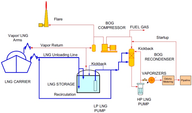
Startup of the LNG regasification terminal is simpler than the liquefaction plant but the basic pre-commissioning and commissioning procedures are quite similar. The units that need to be started up are the LNG unloading system, LNG storage tank, LP pump and recondenser, HP pump, vaporizers, and sales gas piping system. The process flow diagram for a typical LNG regasification terminal is shown in Figure 3.
When the unit is fully commissioned, the equipment should be under positive nitrogen pressure. All lines are pressure and leak tested, dried, and free from dirt and debris. The LNG terminal is now ready to be cooled down and started up as described in the following.
Preparation of flare
To ensure plant safety, the first step in starting up an LNG receiving terminal is purging equipment and piping with nitrogen. All equipment should be purged to the flare to ensure oxygen is removed from the equipment, and a positive nitrogen pressure is maintained to prevent air ingress from the flare. After the flare header is purged, the flare tip can be started. If no fuel gas is available for the firing of the flare pilots, propane from propane bottles can be used.
Cooldown of unloading system
After arrival and mooring of the first LNG carrier, the vapor return arm and the unloading arms can be connected to the LNG carrier. In order to cool down the LNG unloading arms, LNG boil-off gas is routed via the unloading arms through the empty LNG storage tank to the flare. This cold gas from the LNG carrier slowly cools down the unloading arms and the unloading lines. When the system is cooled, one of the LNG carrier’s pumps can be started on recirculation while LNG is introduced slowly to the LNG unloading system. The flashed vapor is routed via the LNG storage tank to the flare. No return vapor is available since the BOG compressor is not yet operating. The LNG carrier is equipped with its own vaporizer to produce its own boil-off gas for tank pressure control and fuel gas requirement.
Cooldown of storage tanks
When the unloading lines have been filled, the next step is to cool the LNG storage tank down to the operating temperature. After this cooldown step, the LNG storage tank is ready to receive LNG. The tank is provided with a cooldown spray ring. This ring is located in the upper part of the tank. LNG from the unloading lines is routed to this spray ring from where it is sprayed into the warm tank. The evaporation of the LNG cools down the tank vapor space and ultimately the tank inner container.
The LNG storage tank cooldown is a critical activity. If performed incorrectly it can seriously damage the tank. The cooldown of the LNG storage tank is therefore normally performed under the direct control of the tank vendor, who will advise on permitted cooldown rates. When the tank tem-perature is low enough, according to the tank vendor, the LNG can be diverted from the spray ring to the main tank fill lines. The flow of LNG from the ship to the LNG storage tank can then be gradually increased up to design rates.
BOG compressor/recondenser
After the nitrogen is sufficiently vented from the LNG storage tank, one BOG compressor can be started with the minimum flow control valve using valve unloaders. After establishing a constant RPM, the compressor is brought into full operation by closing the unloading valves. Boil-off gas from the BOG compressor is directed to the recondenser and then to the flare or fuel gas system while cooling down the recondenser vessel and associated piping.
LP LNG pump
After establishing the liquid level in the LNG storage tanks, the LP LNG system can be started. In the beginning, one LP LNG pump is started with the pump’s minimum flow valve open. The LP LNG is slowly directed to the inlet of the vaporizers using startup lines and is recirculated back to the storage tanks. High point vents are slightly opened such that the lines are slowly filled with liquid. When the sendout piping is liquid filled, the LP pump recirculation line can be slowly closed. A slip stream of LNG is routed to the recondenser for cooldown, preparing the recondenser for startup. The HP pump suction line is filled with liquid and the LNG sendout system is ready to be started up. BOG generated from the cooldown operation can be recovered as fuel gas or vented to the flare. When an LNG carrier starts unloading, BOG can also be used as return vapor to the ship.
HP LNG pumps and vaporizers
The next step is starting the gas export. If submerged combustion vaporizers are used, start the burners as required. After establishing the required water-bath temperature, the HP LNG pump is started on minimum flow spill back.
Thereafter LNG is introduced slowly to the downstream system by opening the control valves in the vaporizer inlets by activating the downstream pressure controller. Once liquid is routed to the vaporizers, the pump kickback is reduced. When the pressure downstream of the vaporizer is established, gas export can be started. As necessary, one or more LP and HP pumps are started, and other vaporizers are brought on-stream. The LNG terminal is then in the production mode. Flaring will be stopped since the surplus BOG can be condensed in the recondenser.
LNG regasification terminal shutdown
Normally, in an LNG regasification terminal, equipment maintenance is very minimal, except the high head HP LNG pumps. However, in case of emergency, the facility must be safely shut down to place the LNG system on a standby mode.
During this situation, the ESD valves will operate to isolate the LNG facility from the LNG cargo ship and the natural gas pipeline. The LP and HP LNG pumps will stop with the recirculation valves open to the LNG storage tanks. The inlet valves to the vaporizers will be closed. The heat source to the vaporizers will be stopped. The BOG compressor will stop with the recycle valve open. Excess BOG will be vented to the flare system. The LNG unloading arm’s shutdown valves will be closed and the LNG transfer system will be stopped.