This article contains information about Fundamentals of LNG technologies in treating and conditioning the sour feed gas and the removal of contaminants.
Gas treatment includes processes of condensate extraction from gas (gas condensate is a compound of heavy hydrocarbons), dehydration, purification from mechanical impurities, purification from acid components – from hydrogen sulfide and carbon dioxide. Purification of gas from acid components is carried out to prevent their corrosive effect on pipelines and equipment and to bring their content in gas in compliance with sanitary standards. Necessity of this or that type of gas treatment is determined depending on specific conditions.
- Introduction
- LNG production plants
- Inlet separation facility
- Condensate stabilization unit
- Condensate hydrotreating unit
- Gas treatment section
- Acid gas removal unit
- Dehydration and mercaptans removal unit
- Mercury removal unit
- Sulfur recovery unit
- Tail gas treating unit (TGTU)
- Acid gas enrichment unit
- Sulfur scavenger unit
- Integrated gas treating and sulfur recovery technologies
- NGL recovery unit
- Lean oil absorption
- Dewpointing by joule-thomson cooling
- Dewpointing by refrigeration cooling
- Deep dewpointing
- High propane recovery
- Medium ethane recovery
- High ethane recovery
- High pressure absorption
- NGL fractionation unit
- Natural gas liquefaction plant
- Integrating NGL recovery and natural gas liquefaction plant
- Nitrogen removal unit
- End flash nitrogen removal processes
- Upstream nitrogen removal processes
- Nitrogen removal process selection
- Nitrogen removal process integration
Introduction
The acid gas contents in most oil and gas production fields have been increasing gradually as CO2 is injected into the reservoirs for sequestration, and nitrogen is injected to stimulate oil production for enhanced oil recovery. The treating and conditioning processes are becoming more challenging, particularly for conditioning gas to the high purity that is required for liquefied natural gas (LNG) projects.
This chapter discusses the different Fundamentals of Liquefied Natural Gastechnologies in treating and conditioning the sour feed gas to the natural gas liquefaction plant, and the technology in the removal of contaminants to meet envi-ronmental and emissions regulations and LNG feed gas specification. NGL recovery is necessary to produce a residual gas with heating value or Wobbe Index that meets the sales gas specification while reaping the economic benefits of the liquid products. Nitrogen rejection technologies are required to maintain the feed gas compositions under control and minimize the liquefaction horsepower within the acceptable value, which are addressed in this chapter.
LNG production plants
The feed gas from the well heads typically contains various contaminants and acid gases that cannot be sent directly to the liquefaction unit. It must pass through different processing units for removal of the undesirable components. The processing units of a typical LNG production plant are shown in Figure 1.
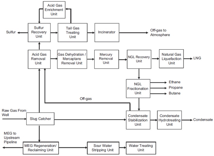
These units work together to deliver an LNG product that would meet the specifications given in Table 1. As can be seen, there are two LNG product specifications: one for the LNG from the liquefaction plant and the other one for the LNG unloaded at customer port. The difference is due to the boil-off of the volatile components from heat leaks during storage, Filling Limits for Cargo Tanks on Liquefied Gas Tankersship loading and unloading, and ship voyage.
Note that the actual LNG plant configuration may vary, depending on the feed gas compositions, product slates and specifications, environmental regulations, and emissions limits. The plant com-plexities and process unit setup are also functions of the plant size, the acid gas contents, sulfur content, and the contaminant levels, which must be studied in depth to arrive at the viable plant configuration.
Inlet separation facility
Field production upon arrival at the LNG production plant will be processed in a slug catcher, which catches the largest liquid slugs expected from the upstream operation and then allows them to slowly drain to the downstream processing equipment to prevent overloading the system.
The slug catcher design is either a vessel-type or finger-type. A vessel-type slug catcher is essentially a knockout vessel (Figure 2). The advantages of the vessel-type are that they require significantly less installation area, are simple in design, and are easy to maintain.

The traditional finger-type slug catcher consists of multiple long pieces of pipes (“fingers”), which together provide the surge volume (Figure 3). The finger-type design is generally less expensive than the vessel-type in high pressure operation. The disadvantage is the large footprint requirement. It is limited to land base facilities where there is no space constraint.

The vessel-type slug catchers typically are used only if the incoming liquid volumes are fairly stable and relatively small. When the incoming liquid flow is uncertain, such as in long pipelines, the potentially large liquid volumes would require the use of the finger-type slug catcher (Shell, 1998).
The slug catcher serves as a three-phase separator where the gas, hydrocarbon liquids (condensate), and aqueous phase are separated. The flash gas from the slug catcher is further separated in a downstream separator to remove any liquid entrainment, prior to entering the gas treatment section. The condensate is processed in the condensate stabilization unit to reduce the vapor pressure to allow storage in atmospheric storage tanks (Figure 1). If the condensate contains mercaptans and other sulfur components, it must be hydrotreated to meet the total sulfur specification, typically, 50 ppmw in order to meet the export requirement.
Suggested reading: Gas Tank Environmental Control
Monoethylene glycol (MEG), which is required for hydrate prevention, is present in the aqueous phase. The MEG is often contaminated with the salts contained in the formation waters. Since salt is nonvolatile, it will remain in the lean glycol during regeneration, which can cause serious corrosion and fouling problems with equipment and pipelines (Son and Wallace, 2000). There are MEG reclamation packages currently available to remove these salts and other contaminants to maintain the required purity. The processed MEG is collected in a lean MEG tank for reinjection to the production field.
Sour water separated from the slug catcher and other sources typically is treated in a sour water stripping unit for removal of the acid gas and ammonia contents. The stripped water can be recycled to the process units or be further processed in a wastewater treatment system prior to disposal.
Condensate stabilization unit
The condensate, a hydrocarbon liquid, separated from the slug catchers contains the dissolved light hydrocarbons and H2S, which must be removed from the liquid to meet the export condensate specifications. A condensate stabilization unit typically is designed to produce a condensate with 4 ppm H2S and RVP (Reid Vapor Pressure) specification of 8 to 12 psi.
A typical condensate stabilization unit is shown in Figure 4. The hydrocarbon liquids are let down to an intermediate pressure in the medium pressure (MP) flash drum. The flash gas is compressed back to the feed gas section, and the flashed liquid is further reduced in pressure prior to entering the condensate stabilizer column. The stabilizer is a fractionator that is heated with steam. The overhead vapor from the stabilizer is compressed and recycled back to the feed section. The combined gas stream is sent to the acid gas removal unit (AGRU). The condensate is heat exchanged with the stabilizer feed, then cooled and exported as the stabilized condensate. If significant amounts of mercaptans are present in the feed gas, the condensate would need to be further treated, typically by hydrotreating, to meet the product sulfur specification.

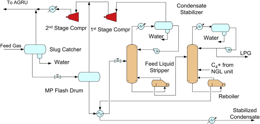
The condensate stabilization unit can also be designed to produce an NGL product, as shown in Figure 5. In this configuration, a feed liquid stripper (FLS) is added before the stabilizer, which removes the C2 and lighter components. The stripper overhead is recycled back to the feed section, and the bottom is fractionated in the stabilizer into a LPG overhead and C5+ condensate bottom products.
Condensate hydrotreating unit
The function of the condensate hydrotreating unit is to remove sulfur compounds from the condensate to meet a desulfurized product specification of 50 ppmw total sulfur. There are several challenges in the design of a hydrotreating unit for the condensate produced from sour gas (Schulte et al., 2009). These include the presence of elemental sulfur, the wide condensate boiling ranges, uncertainties on compositions, and limited data on distribution of sulfur species and aromatic compound and metal contaminants.
Read also: Ship/Shore Interface in Gas trading
In the hydrotreater reactor design, various sulfur compounds such as mercaptans, sulfides, and elemental sulfur are reacted with hydrogen at high temperature and pressure in the presence of a hydrotreater catalyst. The sulfur contents are converted to H2S producing a sulfur-free hydrocarbon (R-S-H + H2/R-H + H2S, where R = Hydrocarbon chain).
Conditions in the reactor are designed to keep the elemental sulfur in solution and avoid deposition of solids on the catalysts. This typically requires a lower operating temperature and higher operating pressure than typically used in naphtha service. Although the purpose of the hydrotreater is desul-furization, some saturation of aromatic compounds also occurs. The configuration of the hydrotreater unit is conventional and similar to refinery application, and primarily consists of the following sections:
- High pressure reactor loop:
- Sulfur compounds and elemental sulfur in the condensate are converted to H2S. The reactor effluent is cooled, and product liquids are separated from the recycled gas in a product separator.
- Low pressure stripping section:
- The condensate product from the separator is stripped to remove H2S and H2.
- Makeup hydrogen compression:
- Hydrogen from the hydrogen plant is compressed to the reactor loop pressure.
- Hydrogen plant:
- Supplies high purity makeup hydrogen to the high pressure reactor loop.
Gas treatment section
While each facet of the LNG production plant is important, the gas treatment section of the plant plays a critical role in treating the gas to meet its final sulfur specifications and to meet the purity levels required by the natural gas liquefaction unit. The specifications to be met are H2S removal to under 4 ppmv, CO2 to 50 ppmv, total sulfur under 30 ppmv as S, water to 0.1 ppmv, and mercury (Hg) to levels of 0.01 mg/Nm3 (Klinkenbijl et al., 2005).
Acid gas removal unit
The acid gas removal unit (AGRU) mainly removes the acidic components such as hydrogen sulfide (H2S) and carbon dioxide (CO2) from the feed gas stream. For Fundamentals of Liquefied Natural GasLNG production, CO2 must be removed to a level between 50 ppmv and 100 ppmv to avoid freezing in the cryogenic exchanger, and H2S must be removed to meet the sales gas specification of 4 ppmv, or one-quarter grains per 100 scf. Addi-tionally, COS, mercaptans, and other organic sulfur species that contribute to sulfur emissions must be removed. However, to meet today’s stringent sulfur emission requirements, the AGRU alone cannot meet the required specifications, and treated gas from these units must be polished with other processes such as molecular sieves, which are specifically designed for removal of the other sulfur components.
A number of processes are available to remove H2S and CO2 from natural gas (Stone et al., 1996; Clarke and Sibal, 1998). Some have found wide acceptance in the LNG segment of the industry while others are currently being considered. The selection of an acid-gas removal process can have a significant impact on project economics, especially when the feed gas contains a high percentage of acid gas. Carbon dioxide and hydrogen sulfide in the feed gas will also significantly impact the thermal efficiency of the LNG liquefaction process due to the fact that AGRU is an energy intensive process.
The main considerations for treating a high CO2 content feed gas are energy consumption and the extent of hydrocarbon coabsorption. A high energy consumption process such as amine will lower the thermal efficiency of the liquefaction plant and generate more greenhouse gases, whereas a physical solvent process will lower the energy consumption but will coabsorb more hydrocarbons. Coabsorption of hydrocarbons has two negative effects. First, it reduces the heating value of the product gas, and second, the higher hydrocarbon contents in the sulfur plant (SRU) feed will cause equipment fouling problems and increase emissions.
There are three commonly used solvent absorption processes for acid gas removal in base load LNG plants: chemical absorption, physical absorption, and the mixed solvents processes (Klinkenbijl et al., 1999). The other processes have limited applications. General information and Rules for Ships carrying LNG and LPGMembrane separation is only suitable for bulk acid gas removal, and the other processing methods, such as cryogenic fractionation and fixed beds adsorption, are not cost competitive.
Chemical solvent processes
Chemical absorption processes, which chemically absorb the H2S, CO2 and to some extent COS, will not remove mercaptans down to low levels due to the low solubility of these components. The advantage of a chemical solvent process such as amine is that the solubility of aromatics and heavy hydrocarbons in the aqueous solvent is low, hence lower hydrocarbon losses. The disadvantage is their high energy consumption in amine regeneration heat duty and cooling duty.
Common examples of amine processes are aqueous solutions of alkanol amines such as mono-ethanolamine (MEA), diglycolamine (DGA), diethanolamine (DEA), diisopropanolamine (DIPA), and methyldiethanolamine (MDEA). With the exception of MDEA, amines are generally not selective and will remove both CO2 and H2S from the gas. Amine can also be formulated by solvent suppliers to increase their selectivity and/or absorption capacity (Hubbard, 2009). Typically, the MDEA selectivity toward H2S is highest at low operating pressures such as in the tail gas unit, but its selectivity is significantly reduced at high pressure.
When used in treating sour gases to meet the tight CO2 specification for LNG plant, the activity of CO2 absorption is too slow with pure MDEA, which must be enhanced with a promoter. The most widely used promoted MDEA process is the aMDEA process, which was originally developed by BASF. The aMDEA process uses piperazine as an activator in MDEA for CO2 absorption. Since the patent on the use of piperazine with MDEA has expired, the solvent can now be available from several amine suppliers such as Dow, Huntsman, and INEOS. The process can also be licensed from technology licensors such as BASF, UOP, Shell, Lurgi, and Prosernat.
A typical amine process is shown in Figure 6. The feed gas is scrubbed in an amine contactor that consists of an amine absorption section and a water wash section. The amine absorption section removes the acid gases from the sour feed gas by contacting with a lean amine. The treated gas is washed in the water wash section to recover amine from the treated gas. The water wash section reduces amine makeup requirement and minimizes fouling in the molecular sieve unit.
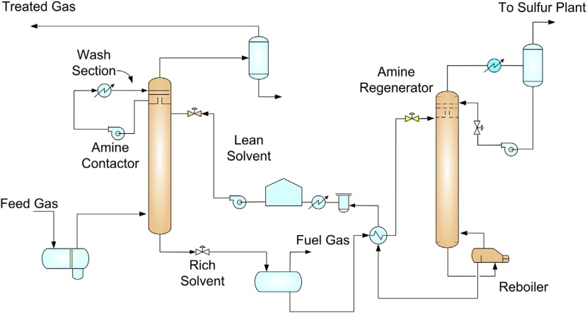
The rich amine from the amine absorber is flashed in a rich amine flash drum, producing a flash gas that can be used for fuel after being treated with amine. Typically, a lean rich exchanger is used to reduce the regeneration reboiler duty. The amine is regenerated using steam or another heating medium. The lean amine is cooled, pumped, and recycled back to the amine absorber.
The common problem in operating an amine unit is foaming in the amine contactor. Liquefied Natural Gas Projects, calculation of the cost of gas productionSour gas from the high pressure separator is at its hydrocarbon dewpoint, such that the lean amine temperature must be controlled at some margin above the sour gas temperature, typically at 10 °F to prevent condensation and subsequent foaming in the absorber. In hot desert areas, where cooling water is not available, process cooling must be by air coolers. In most areas, it is difficult to cool the process gas to below 150 °F. In the amine absorber, removal of the acid gases would increase the gas dewpoint temperature, which means that the lean amine temperature would need to be further increased. A high lean amine temperature would lower the equilibrium loading of the rich amine, increasing the amine flow rate, making treating difficult. To allow the absorber to operate in hot climate areas, feed gas chilling is required, which can be done with the use of propane refrigeration. The feed gas can be chilled to remove the hydrocarbons, reducing the hydrocarbon dewpoint, which would allow the amine contactor to operate at a lower temperature, hence reducing the solvent circulation.
Physical solvent processes
Physical absorption processes use a solvent that physically absorbs CO2, H2S, and organic sulfur components (COS, CS2, and mercaptans). Physical solvents can be applied advantageously when the partial pressure of the acid-gas components in the feed gas is high, typically greater than 50 psi. Note that the physical solvent acid gas holding capacity increases proportionally with the acid gas partial pressure, according to Henry’s law, and can be competitive to chemical solvent processes because of the higher loading and less heating duty. However, physical solvents are not as aggressive as chemical solvents in deep acid gas removal, and may require additional processing steps. Depending on the acid gas contents, a hybrid treating system, such as a physical solvent unit coupled with a sulfur scavenger, may be a better choice than a single amine system (Mak et al., 2012).
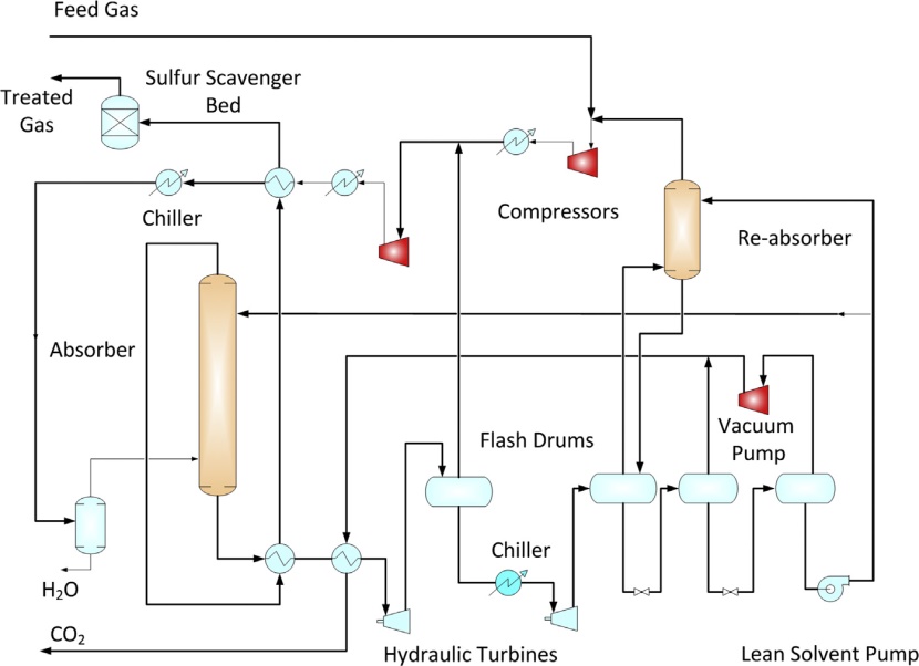
There are several proven physical solvent processes such as Selexol® (licensed by UOP), Fluor® Solvent (licensed by Fluor), or Purisol® (by Lurgi). The main advantages of physical solvent processes are that the solvent regeneration can be partially achieved by flashing of the solvent to lower pressures, which significantly reduces the heating requirement for regeneration. In some processes, such as the Fluor Solvent process (Figure 7), no heating is required as the solvent is regenerated by vacuum flashing or by stripping with treated gas or inert gases. When used in treating high pressure, high acid gas content gases, Environmental aspects in Liquefied Natural Gas productiongreenhouse gas emissions from physical solvent units are significantly lower than the amine units.
The main disadvantage of the physical solvent unit is the coabsorption of hydrocarbons, which results in Btu losses in the CO2 effluent. Energy savings could be offset by the losses in product gas. Unlike an amine unit where the process design is quite straightforward, physical solvent unit designs are more complex. Most of the physical solvent processes are licensed processes and the process configurations and operating conditions vary depending on the licensed solvent used. Typically, physical solvent units require additional equipment, such as recycle compressor, refrigeration, stripper, and flash drums. Gas recycling reduces the hydrocarbon losses, which, however, also increase the (Mak et al., 2012) solvent circulation. If treated gas is used for stripping, the stripper overhead gas can be recycled back to the absorber, which also increases the solvent circulation.
Therefore, the design of a physical solvent unit is more involved and must be carefully optimized in order to realize the advantages of the physical properties of the solvent.
Mixed solvents processes
Mixed solvents processes use a mixture of a chemical and a physical solvent. They are used to treat high acid gas content gases while meeting the deep removal of the chemical solvents. To some extent, these favorable characteristics make them a good choice for many natural gas treating applications. The Shell Sulfinol process is the one of the proven mixed solvent processes.
Process selection considerations
The selection of the acid gas removal technology in an LNG plant is dependent on the feed gas composition and conditions, the product gas specifications, and the availability of utilities. For example, if waste heat is available, then amine units may be selected since they can be used as a heat sink for heat rejection. However, when a heat source is not readily available, a physical solvent may be a better choice. But other criteria such as hydrocarbon coabsorption, removal of aromatics, and operating flexibility should be considered in conjunction with the capital and operating costs.
Feed gases with low acid gas contents are easy to treat, but these fields are becoming scarce. Most of today’s gas fields are sour gas fields. These fields commonly contain 10 to over 20 mole % acid gases. Sour gas fields with CO2 content of over 50 mole % will eventually be explored. With the everincreasing environmental constraints and the concerns on greenhouse emissions, the straightforward sweetening unit in the past may no longer be sufficient. Innovative acid gas removal methods, more complex configurations, and nonsolvent technologies need to be considered. This may include bulk removal of CO2 via membranes. Designed for operational simplicity, membrane systems are an excellent choice for small plants, particularly in offshore locations. With high pressure feed gas, they may not require compression equipment. Chemical reagent monitoring or makeup is not required. The membranes are prefabricated units, which reduces installation costs and plot space. However, membranes can only reduce the CO2 content down to a few volume % and further treating with amine is required to meet the required CO2 specification of 50 ppmv (Bauer, 2011). The disadvantage of membrane separator is the high hydrocarbon content in the CO2 permeate gas, which may not be a loss if the CO2 is reinjected for enhanced oil recovery. However, hydrocarbon losses can also be reduced by multiple units and recycling the permeate gas. The membrane elements are also susceptible to degradation by aromatics and condensation of hydrocarbons, and the unit should be protected by a pretreatment unit. Although a membrane unit by itself may seem compact and simple, the additional pretreatment, compression equipment, the replacement cost of the membrane elements and the hydrocarbon losses must be considered in the life cycle analysis when compared to other treating options. When treating a high pressure sour gas, with a high CO2 to H2S ratio, coabsorption of CO2 cannot be avoided. In this situation, an H2S selective solvent such as dimethylpolyethylene glycol (DMEPG) can be a viable option. DMEPG is marketed by Dow as the Selexol solvent or by Clariant as the Genosorb solvent. The DMEPG solvent process can be licensed from UOP as the Selexol process or from Fluor as the EconoSolv process. The process consists of an H2S removal section and a CO2 removal section (see Figure 8).
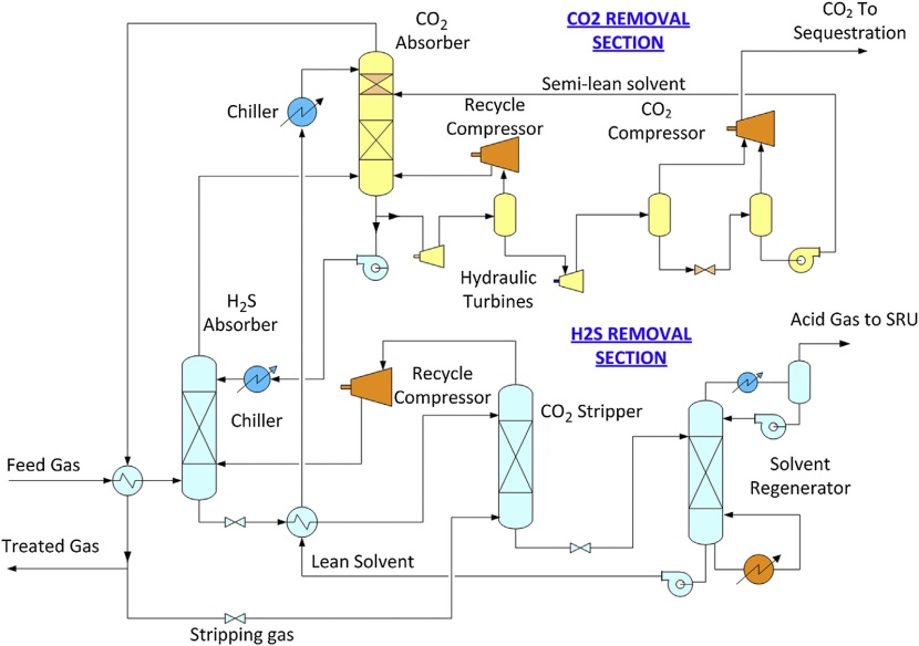
In the H2S removal section, the H2S content is removed from the feed gas using a CO2 saturated lean solvent from the CO2 section. In order to concentrate the H2S content in the acid gas, the CO2 content in the solvent is stripped using a slip stream of the treated gas. The stripper overhead gas is recycled back to the H2S absorber to reduce hydrocarbon losses. This operation effectively reduces the CO2 content in the rich solvent, hence increasing the H2S content in the acid gas to the Sulfur Recovery Unit. The rich solvent is regenerated with steam in the solvent regenerator to produce a lean solvent that is used in the CO2 section. The CO2 content in the sulfur-free gas from the H2S section is removed in the CO2 absorber. In the CO2 section, the CO2 rich solvent is regenerated by flash regeneration by reducing pressure at various levels. The high pressure CO2 can be fed directly to the CO2 compressor, which significantly reduces the compression horsepower for CO2 sequestration. This configuration can be used to capture over 95 % of the carbon content in gasification application (Mak et al., 2010).
Dehydration and mercaptans removal unit
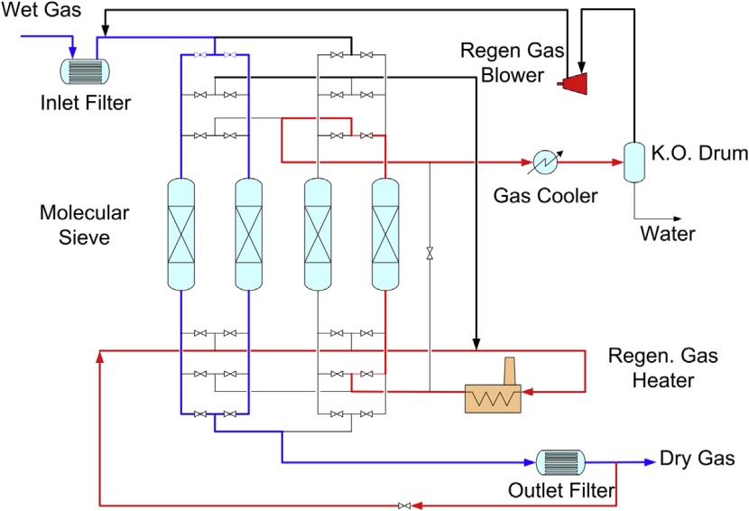
The second step in the treating process is a Molecular Sieve Unit (MSU), which is designed to meet the product specifications on water and mercaptans (RSH) content. The MSU can be designed to remove water to 0.1 ppmv and most mercaptans to 2 to 3 ppmv. When molecular sieves are used for mer-captans removal, water must be removed first before the mercaptans removal bed. Removal of water and mercaptans on molecular sieves can be installed in a single vessel, where the first layers of mo-lecular sieves remove water, and the subsequent layers of molecular sieves remove mercaptans. Often, 4A, 5A, and 13X molecular sieves are used for the removal of water, light mercaptans, and heavy mercaptans, respectively. Additional layers of specific adsorbents may also be used to remove traces of mercury and to protect the molecular sieves from plant upsets and unexpected contaminants (Northrop and Sundaram, 2008).
Design of the dehydration and mercaptan-adsorption unit is based on the number of fixed beds in a parallel lineup, as shown in Figure 9. In a typical operation, four molecular sieves beds are used, with two of the adsorbers on drying the sweet gas from AGRU, one adsorber is being thermally regenerated by desorbing the compounds, and the other adsorber is being cooled before being returning to the next cycle. Each molecular sieve adsorber is typically in adsorption mode for 6 hours, followed by 3 hours of heating and 3 hours of cooling. Every 12 hours, the cycle returns to the same point and is repeated.
The cyclic operation of the molecular sieve unit imposes stress on the sieve materials and the beds are typically replaced once every 3 to 5 years. The operation conditions of the cycles, such as flow rates, pressures and temperatures, and regeneration conditions should be evaluated in a dynamic model that can be used to optimize the dehydration operation and extend the bed life (Mock et al., 2008).
If the solvent used in the AGRU is a physical solvent or mixed chemical/physical solvent, a sig-nificant portion of the mercaptans may have already been removed in the AGRU, thereby reducing the molecular sieve mercaptans removal requirement. On the other hand, chemical solvents such as DEA, DGA, or MDEA (accelerated) do not absorb any appreciable amount of heavy hydrocarbons and mercaptans, which must be handled by the downstream molecular sieve unit. When the molecular sieves are regenerated, the wet molecular sieve regeneration gas containing the mercaptans is returned to the AGRU inlet. The mercaptans concentration in the gas entering the AGRU will build up until the amount removed in the AGRU equals the incoming mercaptans.
The split of the mercaptans removal between the ARGU and the molecular sieves should consider factors such as operating flexibility on different gas compositions and flow rates, environmental and emissions, and operating and capital costs (Klinkenbijl et al., 1999; Grootjans, 2005).
When using the molecular sieves for both dehydration and mercaptans removal, the amount of mercaptans must be purged from the system by one of several means, such as:
- Use the wet regeneration gas as fuel gas. This is unlikely as the regeneration gas typically far exceeds the plant’s fuel gas requirement. Also the sulfur oxides from incineration of the mercaptans may exceed the plant’s sulfur emissions limit;
- Add a physical solvent AGRU to treat the regeneration gas.
The regeneration gas from the AGRU is processed in the Sulfur Recovery Unit (SRU). If an amine unit is used as the AGRU, the majority of mercaptans will come from the molecular sieve beds during regeneration. The mercaptans release will vary during the regeneration cycle and will peak at some point. This has an impact on the SRU as the SRU catalyst is designed for a certain mercaptans level and is very sensitive to mercaptans load changes (Carlsson et al., 2007; Bradley et al., 2009). To avoid fouling of the SRU catalysts from excessive mercaptans loads, some leveling facilities should be provided to even out the mercaptans flow to the SRU.
The branched-type mercaptans that slip through the AGRU usually are not caught by the molecular sieves and are left in feed gas to the downstream unit. Since these branched type mercaptans have volatility close to pentane, they are removed together with the NGL stream and will concentrate in the pentane plus condensate. To meet the sulfur specification in the condensate product, further processing such as hydrotreating is required.
Mercury removal unit
Almost every LNG plant will have a mercury removal unit installed. This is because the consequence for the LNG plant from mercury attack is severe and because it is difficult to predict the mercury contents from production reservoirs. Low levels of mercury can result in severe corrosion of the brazed-aluminum heat exchangers used in cryogenic systems, and potentially can pose environmental and safety hazards. The presence of mercury in the feed stocks to petrochemical plants will also cause poisoning of precious metal catalysts (Carnell and Row, 2007). For this reason, the LNG plant is designed with a conservative design that requires mercury removal to levels below 0.01 mg/Nm3.
Most of the current methods for removing mercury from natural gas and hydrocarbon liquids use fixed beds of mercury removal materials. The fluid flows through the fixed bed in which mercury reacts with the reactive reagent in the mercury removal vessel producing a mercury-free product (Kidnay and Parrish, 2006).
There are two types of mercury removal materials: nonregenerative mercury sorbents, and regenerative mercury adsorbents.
Non-regenerative mercury sorbents
In the nonregenerative mercury removal process, the mercury reacts with the sulfur to form a stable compound on the sorbent surface. A number of different mercury removal sorbents are available with various tolerances to operating temperature, liquid hydrocarbons, and water (Markovs and Clark, 2005). The use of sulfur-impregnated activated carbon is a proven commercial process for removing the mercury. However, there are drawbacks to this method of mercury removal, where sulfur- impregnated carbon can only be used with dry gas since it has a high surface area and small pore size. This also restricts the access of mercury to the sulfur sites and increases the length of the reaction zone. Also, sulfur can be lost by sublimation and dissolution in hydrocarbon liquids. This again reduces mercury removal capacity. Furthermore, it is often difficult to dispose of the spent mercuryladen carbon material (Abbott and Oppenshaw, 2002).
Recognition of these problems has led to examining technologies other than sulfided carbon, where a range of nonregenerable absorbents utilizing transition metal oxides and sulfides instead of carbon have been developed to improve on existing mercury removal technologies, in which the discharge absorbents can be safely handled. In these systems, the reactive metal is incorporated in an inorganic support and the absorbent is supplied with reactive sulfide component by either ex-situ or in-situ sulfiding (Carnell and Row, 2007). Johnson Matthey has taken this concept further and supplied an established range of absorbents marketed under the PURASPEC™ brand. The PURASPEC™ materials are a mixture of copper sulfide/copper carbonate, zinc sulfide/zinc carbonate, and aluminum oxide, which can operate in a wet gas environment (Row and Humphrys, 2011).
Note that the nonregenerative methods appear to be simple since no regeneration equipment and special valving is required. However, disposal of the used sorbent can be a problem since the sorbent not only picks up the mercury, but it will often contain other hazardous material such as benzene and other hydrocarbons (Markovs and Clark, 2005).
Regenerative mercury adsorbents
The regenerative mercury removal process uses silver on a molecular sieve (such as the HgSIV UOP sieve) to chemisorb elemental mercury. The mercury-saturated layer is then regenerated with hot regeneration gas. The regeneration gas is usually heated to 550 °F. The mercury can then be recovered in condensed water. With this method of mercury removal, since the mercury does not accumulate on the adsorbent, it will avoid problems with removal of the spent adsorbent. However, traces of mercury will remain in the regeneration gas, which can be removed with a non-regenerative mercury bed (Markovs and Clark, 2005).
Process selection issues
There are four possible options for mercury removal.
- Option 1: Installing nonregenerative mercury removal sorbents at the plant inlet. This option removes all the mercury and ensures no mercury contamination in the rest of the plant (Edmonds et al., 1996). However, the large volume of feed gas and acid gases require a large removal system, which may be challenging in design and operation;
- Option 2: Installing a nonregenerative mercury removal sorbent downstream of the acid gas removal unit, just before the molecular sieve unit. This option reduces the size of the beds to some extent, but it poses the risks of mercury contamination in the AGRU solvent system;
- Option 3: Add a silver-impregnated mercury sieve section to the molecular sieve beds. Although this option can remove water, mercaptans, and mercury at the same time, and avoid the need of a separate mercury bed, it presents problems with a high mercury content in the regeneration water that would pose operating hazards unless treated by another mercury removal step (Hudson, 2010);
- Option 4: Installing a nonregenerative mercury removal bed or a silver-impregnated molecular sieve bed after the molecular sieve unit. While this option yields good mercury removal performance, as the feed gas is dried and clean, it cannot avoid the mercury contamination problem in the AGRU and molecular sieves upstream and may pose operating hazards (Eckersley, 2010).
Life cycle costs, adsorbent disposal methods, mercury levels, environmental limits, operating hazards, and plant operator procedure must be evaluated in the selection of a suitable mercury removal system. The optimum mercury removal method can also be a combination of nonregenerative and regenerative mercury removal system (Markovs and Clark, 2005).
Sulfur recovery unit
In a typical gas treating unit, acid gas from the regenerator contains significant amounts of H2S that must be further processed and cannot be vented or flared. In the past, the acid gas could be reinjected for sequestration, but recent research indicated that the sulfur compounds would have long term negative impacts on the reservoirs and formation. Today, acid gas is generally processed in a sulfur recovery unit that is closely coupled with a tail gas unit. With this combination, the sulfur recovery system can meet the 99.9 % sulfur removal target, which is needed to meet today’s emission requirements.
There are many sulfur technologies that are available with different performance in terms of operation and results. The selection of the sulfur technology is mainly depending on the amount of H2S, CO2, and other contaminants in the feed gas. As a rule of thumb, liquid redox technology is suitable for small sulfur plants (below 20 tons per day), and for the larger units, such as those used for LNG production, the Claus sulfur technology is the most common (Hubbard, 2009).
Claus technology
The common method for converting H2S into elemental sulfur in a gas plant is the Claus-based process, which is available from several sulfur plant licensors. The Claus process is basically a combustion unit, and to support the sulfur conversion reaction, the acid gas must contain sufficient H2S to support the heat of combustion. Typically, the H2S content in the acid gas must be greater than 40 mole %. If the feed gas contains insufficient H2S, additional processing steps are required, which may require supplemental preheating, oxygen enrichment or acid gas enrichment (Mokhatab and Poe, 2012). In addition, if the acid gas contains other contaminants such as ammonia, BTEX, and mercaptans, a higher combustion temperature is necessary, which may require even higher H2S content gases.
In a conventional Claus process (see Figure 10), the reaction is carried out in two stages. The first stage is the thermal section where air is used to oxidize about one-third of the H2S content in the sour gas to SO2. This reaction is highly exothermic and typically about 60 to 70 % of the H2S in the sour gas is converted to sulfur. In the thermal stage, the hot gases are cooled to 600 °F to 800 °F and the waste heat is used to generate high pressure steam. During this process, the S2 sulfur species content are converted to other sulfur species, primarily Sg and Sg. The gases are finally cooled, to 340 °F to 375 °F, in a sulfur condenser by generating low pressure steam.
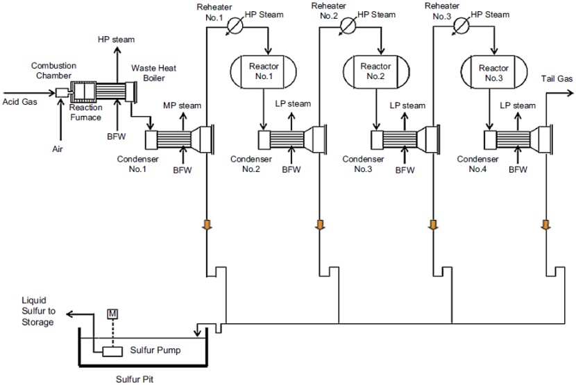
The second stage is a catalytic stage. The residual H2S is converted in three stage reactors where sulfur is converted by reaction of the residual H2S with SO2 at lower temperatures, typically 400 °F to 650 °F. The gas must be preheated first to avoid sulfur deposition on the reactors. Sulfur liquid is condensed from the condenser and is routed to the sulfur pit for degassing.
Typical three-stage Claus sulfur recovery unit.
Sulfur recovery efficiencies for a two-stage catalytic process are about 90 to 96 %, and for a three- stage process, the efficiencies can be increased to about 95 to 98 %. With an additional selective oxidation stage, sulfur conversion can be further increased to 99 %, such as the SUPERCLAUS® process, licensed from Jacob Comprimo.
Sulfur degassing
Liquid sulfur produced from the condensers typically contains 200 to 350 ppmw H2S, partially dis-solved and partly present in the form of polysulfides. If liquid sulfur is not degassed, H2S will be released in the storage tanks, which would create a toxicity hazard and noxious odor problems. Sulfur can be degassed by oxidation and stripping to meet the 10 ppmw H2S specification, using the patented D’GAASS process from Goar, Allison & Associates, licensed from Fluor.
Tail gas treating unit (TGTU)
To meet today’s stringent sulfur emissions requirements, use of the Claus process or the SUPERCLAUS® process alone is not enough, as they are limited by chemical equilibrium. To comply with today’s emissions requirement, the residual sulfur in the effluent from the Claus unit must be further removed by amine treatment in a tail gas treating unit.
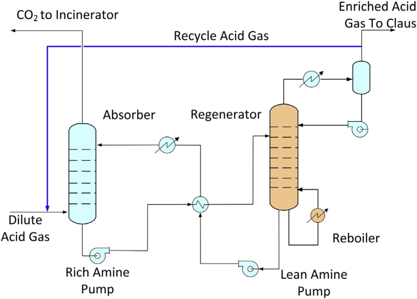
Before the tail gas can be processed in the gas treating unit, the SO2 content must be converted to H2S, which can then be absorbed by a H2S selective amine. The amine absorbs the H2S content, which is recycled back to the front section of the Claus unit. This recycle process was first developed by Shell as the SCOT unit (Shell Claus Off-gas Treating), which became a standard unit to meet today’s emissions requirements. With the use of a selective amine, sulfur recovery of over 99.9 % can be met (Harvey and Verloop, 1976). This recycle design can also be integrated with an acid gas enrichment unit as discussed in the following section.
The tail gas unit designs that are offered by several licensors typically consist of two sections, the hydrogenation section and the tail gas treating section (Figure 11). In the hydrogenation, SO2 is converted to H2S by the hydrogenation catalyst in the presence of hydrogen. The conversion of SO2 must be complete as it will react with amine in the treating unit resulting in amine degradation. The hydrogenated tail gas is then cooled by water in a quench tower. Excess water condensate is removed from the tower and the overhead tail gas is sent to an amine unit.
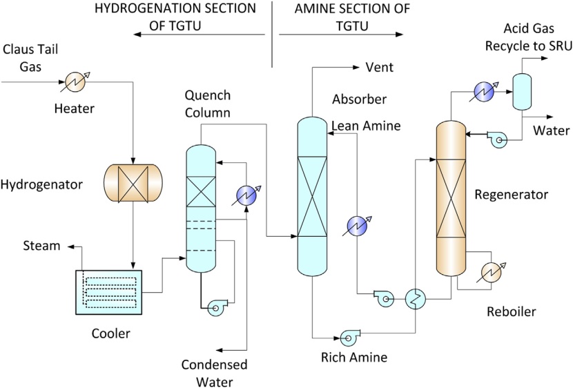
The tail gas to the amine unit consists of mainly CO2 and a very low level of H2S. The tail gas treating unit is designed to selectively absorb H2S while rejecting the CO2 content before it can be sent to a thermal oxidizer or incineration. The H2S selective amine can be a formulated MDEA for sulfur removal or sterically hindered amines. The formulated MDEA is available from several amine suppliers, and the sterically hindered amine, such as FLEXSORB®, can be licensed from ExxonMobil.
It should be noted that H2S absorption equilibrium is favored by low amine temperatures, which may not be achievable with air cooling alone, especially in hot climate areas. Typically a chilled water system or refrigeration is used in the tail gas treating unit.
Acid gas enrichment unit
In a conventional Claus sulfur recovery unit, the acid gas typically contains over 40 mole % H2S, which would provide sufficient heating value to support the heat of reaction. When a sour gas with high CO2 content is treated, the acid gas produced from the treating unit will contain a lower H2S content. To operate the Claus unit, the H2S content in the acid gas must be concentrated by rejecting its CO2 content using an acid gas enrichment unit (AGEU).
Similar to the tail gas treating unit, the acid gas enrichment unit uses an H2S selective solvent such as the formulated MDEA or the sterically hindered amines. There are several patented configurations that can be used to treat lean acid gases. These processes can be used to enrich an acid gas with 10 mole % H2S to as high as 75 % (Wong, 2007). In addition to rejection of CO2, the enrichment unit can also be used to reject hydrocarbons, mercaptans, and other contaminants that are known to be problems with Claus unit operation. These processes are based on recycling a portion of the acid gas from the regenerator back to the absorber, as shown in Figure 12.
Sulfur scavenger unit
With the concerns for global warming, the application of SRU and TGTU may not be sufficient. If less than 1 ppm sulfur specification is required, a sulfur scavenger fixed bed can be used. One of the common sulfur scavenger processes is the PURASPEC process, which can be licensed from Johnson Matthey. PURASPEC has been used as a polishing unit downstream of a gas treating unit. When used in conjunction with a physical solvent unit such as the FLUOR Solvent process, it can be used to treat a wide range of high CO2 gases without the use of heat, hence minimizing greenhouse gas emissions (Mak et al., 2012).
Compared to other sulfur options, a sulfur scavenger is expensive. However, it can produce a treated gas with an H2S content that cannot be economically achieved by other methods. When used by itself alone, the scavenger bed is usually economical for low sulfur feed gases, typically below 500 kg/ day. A process selection chart is shown in Figure 13. For higher sulfur throughput, the sulfur scavenger system can best be used as a polishing unit downstream ofa gas treating unit in combination with a Claus unit or Redox unit.

Integrated gas treating and sulfur recovery technologies
In the past, when treating sour gas with lower CO2, mercaptans and other contaminants, the gas treating process, dehydration, and sulfur technology can be independently selected based on the owner’s preference and there are less technological issues. However, as the feed gas is getting more sour and contains a higher CO2 and mercaptans content, the process selection must be carefully evaluated to ensure the selected technologies are compatible. Today, many licensors and contractors are offering their own suite of integrated technologies for the acid gas removal, dehydration, mercaptans removal as well as sulfur recovery, tail gas treating, and acid gas enhancement. Such integration by a single licensor can avoid the coordination difficulties and can ensure the overall plant performance, as described by Mokhatab and Meyer (2009) and Mokhatab and Poe (2012).
NGL recovery unit
In most gas processing plants, the C5+ gasoline components are separated in the condensate stabilization unit and are sold as a high value liquid product. The residual gas after the condensate unit cannot be sent directly to the gas pipeline as it still contains significant amounts of the hydrocarbon tails and LPG components. These heavy components will result in hydrocarbon condensation in the pipeline when sufficiently cooled. In earlier gas plants where these components were not removed, there were frequent reports on explosion in rural areas. For this reason, pipeline gas hydrocarbon dewpoint is now strictly enforced to avoid such accidents. The hydrocarbon dewpoint of pipeline gas must be at least below the coldest ambient temperature to ensure no hydrocarbon condensation during transmission.
In today’s gas plant, with the advances of the turbo expander plants, Process of Liquefied Natural Gas regasificationremoval of the LPG components and even the ethane components are very efficient and can be economically justified. Most NGL recovery plants can now recover 99 % propane and close to 90 % ethane depending on the gas compositions. However, depending on the price differential between methane and LPG and the market demands, some LNG plants may prefer to recover the minimum amounts, just enough to avoid waxing and free-out of the heavy hydrocarbons in the cryogenic main exchanger. The other aspect is that liquefying the LPG components together with methane requires more refrigeration power than if they are separated upstream at a higher temperature. For this reason, a liquefaction plant would prefer liquefying a lean gas than a rich gas to reduce the liquefaction costs. Where there are demands for ethane for petrochemical production, removal of ethane can also be economically attractive.
In earlier LNG liquefaction plants, the main reason for NGL recovery is to avoid wax formation and free-out of the heavy hydrocarbons when natural gas is liquefied at low temperature. In most design, the use of a simple scrub column is adequate to meet the benzene (C6) requirements for export. Although propane and butane pose no freezing problem, they are removed together with the С6+ hydrocarbons and can later be separated and sold as liquid products.
NGL recovery processes can be classified by the lean oil process, the Joule-Thomson process, the refrigeration process, and the turbo-expander processes. The selection of an NGL recovery process depends on the gas compositions, the gas heating content targets and the opportunities on exporting the LPG or ethane product. The following section describes the different methods that can be used for removal and recovery of these components.
Lean oil absorption
The lean oil absorption process was developed in the 1910s and was common in earlier recovery plants. The process can typically recover about 40 % of the ethane, 90 % of the propane, and 95 % of the pentane and heavier hydrocarbons.
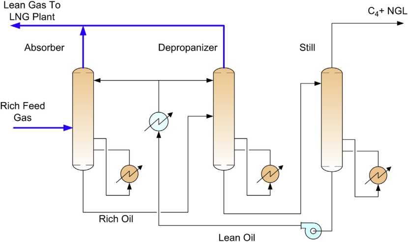
In the lean oil absorption process, the ethane and heavier components in the feed gas is scrubbed and absorbed by a lean oil (molecular weight typically about 100 to 150) in an absorber column. The lean oil can be supplied at ambient temperature or refrigeration temperature. The rich oil exiting the bottom of the absorber is sent to a rich oil depropanizer, which separates the propane and lighter components as an overhead gas. The column bottom is fractionated in a still, where the NGL’s (C4+) are recovered as an overhead product and the lean oil is recycled back to the absorber. A typical flow sheet is shown in Figure 14.
The lean oil process requires a significant amount of heating and cooling. For base-load LNG plant applications, especially when high NGL recoveries are required, lean oil plants are not cost competitive when compared to turbo-expander processes.
Dewpointing by joule-thomson cooling
A dewpointing unit is a cost-effective method to remove water and C5+ hydrocarbon contents for pipeline gas transmission. Dewpointing is achieved by chilling the gas and separating the heavy hydrocarbons.
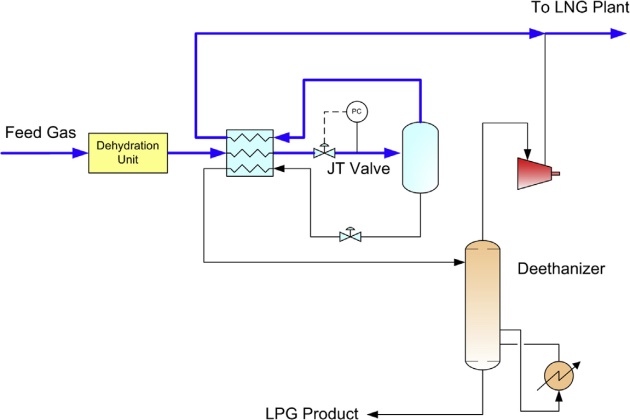
For high pressure feed gas, chilling can be achieved with the use of a Joule-Thomson (JT) valve. The flow schematic of a dewpointing unit is shown in Figure 15. The feed gas is first dried by the molecular sieve unit, and is cooled in a gas-gas exchanger, typically in a plate fan fin exchanger, using the cold gas and liquid from the low temperature separator (LTS). The cold gas is then let down in pressure in the JT valve and is routed to the LTS. The C3+ liquid is separated and is fed to a deethanizer that fractionates the light components from the C3+ heavier liquid. The deethanizer is heated with steam. The overhead vapor is compressed to combine with the LTS overhead gas and fed to the LNG plant. A typical dewpointing unit can achieve 30 to 50 % propane recovery.
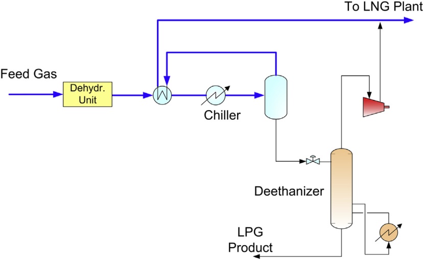
Dewpointing by refrigeration cooling
If the feed gas pressure is low, there is not sufficient pressure differential to generate cooling by the JT valve. In this case, external refrigeration using propane refrigerant is required. The process flow schematic is shown in Figure 16.
Deep dewpointing
If higher propane recovery is desired, the dewpointing unit can be modified to include a turboexpander and absorber. The deep dewpointing unit is shown in Figure 17, which can achieve 70 to 80 % propane recovery.
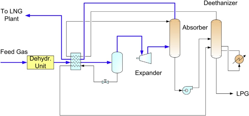
The turbo-expander can generate a colder temperature than either JT cooling or refrigeration. In the deep dewpointing unit, the expander discharge is fed to an absorber, which is refluxed by the ethane rich deethanizer overhead. In the absorber, the C3+ components in the feed gas are condensed by the ethane rich reflux, producing a C3 rich bottom product. The absorber bottom is fractionated in the deethanizer into a C2 rich overhead (used as reflux) and a C3+ LPG bottom product.
High propane recovery
Where propane can be sold at premium value over natural gas, high recovery is desirable. Propane recovery of over 99 % can be achieved with a refluxed absorber and a refluxed deethanizer. This configuration is shown in Figure 18.

Similar to the deep dewpointing unit, refrigeration is generated by the turbo-expander. Feed gas is cooled by the cold absorber overhead vapor. The refrigerant contents in the separator liquid and the absorber bottoms are also recovered in chilling the feed gas. Side reboilers on the deethanizer can also be used to reduce the refrigeration duty. The heat exchange among these streams occurs in a plate and fin aluminum exchanger, which is designed with a close temperature approach.
The absorber bottom is sent to the deethanizer using a pump or by hydraulic head. The deethanizer operates at about the same pressure as the absorber. To improve propane recovery the deethanizer overhead is condensed with refrigeration, producing a C2 rich liquid that is refluxed to both the deethanizer and the absorber.
Depending on feed gas compositions and pressures, the optimum configuration can differ. There are many patented configurations for NGL recovery, and they are different in the respect of flow sequences, heat exchanger design, the use of different reflux streams, and column configuration (Mak et al., 2003). For example, the absorber and the deethanizer can be combined as a single column, as patented by Ortloff’s SCORE process, or the use of multiple reflux streams as patented by Fluor’s TRAP process.
Medium ethane recovery
Where ethane can be exported to a petrochemical feedstock, high purity ethane can be recovered using with the Gas Subcooled Process (GSP). Typically, the GSP process can achieve 70 to 80 % ethane recovery. The GSP process was originally developed by Ortloff over 20 years ago and is a common process for the gas processing industry.
In LNG production, since CO2 has been removed in AGRU to meet the 50 ppmv CO2 specification, CO2 freezing is not a concern in NGL recovery. Because of the absence of CO2, the demethanizer column can operate at a very cold temperature without CO2 freezing problems.
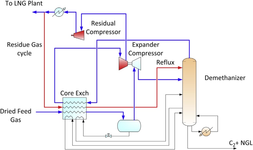
As shown in Figure 19, the GSP process uses a portion of the feed gas to reflux the demethanizer. The feed gas from the separator is split into two portions; about 60 % is let down in the expander to generate cooling, while other portion is chilled and subcooled by the demethanizer overhead to produce a liquid reflux to the demethanizer.

Typically, the demethanizer operates at about 450 psig to 500 psig. Higher pressure would minimize recompression, however the operating pressure must stay below the critical pressure for separation efficiency. The relative volatility between methane and ethane gets closer at high pressure, which is the reason for the fractionation difficulty. The ethane product must contain no more than 1 to 2 volume % of methane, which is difficult to achieve at high pressure.
High ethane recovery
When ethane recovery of over 90 % is required, additional lean reflux must be added by recycling the lean gas from the residue gas compressor as shown in Figure 20. To generate additional cooling, propane refrigeration can be added and the expander can operate at a higher expansion ratio by lowering the demethanizer pressure. The extent of refrigeration requirements depends on the richness of the feed gas, the feed gas pressure, and the desirable level of ethane recovery. Typically, over 95 % ethane recovery is difficult to meet without spending excessive energy for refrigeration.
Similar to the propane recovery configurations, there are variations in the process configurations based on this concept. Some of the configurations are patented technologies that specify different lean refluxes and heat integration methods.
High pressure absorption
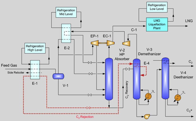
In LNG liquefaction, a high feed pressure is desirable because it reduces the refrigeration cycle compression requirements and increases the liquefaction efficiency. However, when NGL recovery is required, the demethanizer pressure must be at 500 psig or lower for fractionation efficiency reasons. To solve this problem, Fluor has developed the patented TCHAP (Twin Column High Absorption process) concept that uses a two-column approach with the first column (the absorber) operating at a high pressure, typically over 600 psig, and the second column (the demethanizer) operates at a lower pressure, at 450 to 500 psig. The innovation is that the high pressure absorber bottom is let down in pressure, and the refrigeration content in the letdown liquid is used to provide cooling to the reflux condenser in the demethanizer column. The overhead vapor from the demethanizer is compressed with a recycle gas compressor, cooled, and used as a reflux to the high pressure absorber. The final frac-tionation of methane from the ethane product takes place in the second column operating at a lower pressure. The TCHAP process is shown in Figure 21, which can achieve recovery of 70 % ethane and 99 % propane. The high pressure demethanizer overhead vapor is compressed by the expander compressor to typically about 900 psig feeding the LNG plant. There are several variations of this patented process concept. The process can also be used for propane recovery.

NGL fractionation unit
Fundamentals of Liquefied Natural GasOnce natural gas liquids (NGLs) have been removed from the natural gas stream, they must be fractionated into their base components, which can be sold as high purity products. Fractionation of the NGLs may take place in the gas plant but may also be performed downstream, usually in a regional NGL fractionation center. A typical process flow schematic is shown in Figure 22.
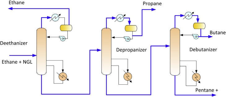
NGLs are fractionated by heating the mixed NGL stream and processing them through a series of distillation towers. Fractionation takes advantage of the differing boiling points of the various NGL components. As the NGL stream is heated, the lightest (lowest boiling point) NGL component boils off first and separates. The overhead vapor is condensed and a portion is used as reflux and the remaining portion is routed to product storage. The heavier liquid mixture at the bottom of the first tower is routed to the second tower where the process is repeated and a different NGL component is separated as product. This process is repeated until the NGLs have been separated into their individual components.
Natural gas liquefaction plant
Natural gas liquefaction requires removal of sensible heat and latent heat from the natural gas at high pressure over a wide temperature range. A number of liquefaction processes have been developed in the past decades with the differences mainly on the choice of refrigerants, refrigeration driver match, and refrigeration configurations. Besides capital and operating costs, the primary objective of these technological innovations is to increase the throughput of a single LNG train.
Integrating NGL recovery and natural gas liquefaction plant
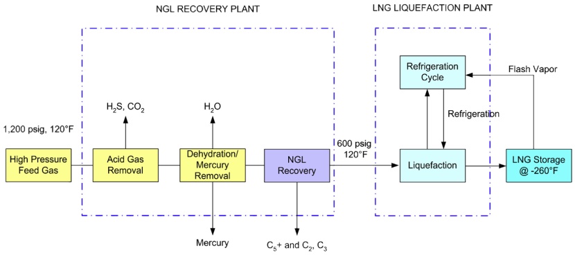
NGL recovery plants can be operated with or without an LNG plant downstream. There are advantages of the standalone NGL recovery plants. They can be operated on NGL recovery, producing sales gas to the pipelines and sending only the required volume to the LNG plants. On the other hand, the lique-faction plant can be designed to have the minimum gas conditioning equipment that allows LNG pro-duction without the upstream NGL recovery plants. This independent operation increases the reliability and availability of both facilities but would require additional costs. The process block flow diagram of a nonintegrated NGL recovery plant and an LNG liquefaction plant is shown in Figure 23. The recovery of NGL can maximize revenues from the LNG plants. The extracted LPG propane can be sold at a premium price over natural gas or they can be blended back to enrich the heating value of LNG for export to Asian markets. Lean LNG is required for export to the United States or Western European markets because of their heating value specifications. Such a blending operation provides the International trade of Liquefied Natural Gas in maritime industryflexibility of exporting LNG to meet the heating value requirements by different markets.
When compared to the standalone process, an integrated NGL/LNG process can eliminate duplication of the heat exchangers and reduce the pressure drop between the two units. Traditionally, an LNG plant is integrated with a scrub column for removal of the heavy hydrocarbons to avoid freeze- up in the cryogenic exchanger. A typical flow schematic is shown in Figure 24. The scrub column normally operates at the feed gas pressure, typically at 700 psig. Because of the high pressure, the scrub column can recover only about 50 to 70 % of the propane while producing a bottom product of the heavier components containing significant amounts of ethane and lighter components. Consequently, a deethanizer is required in additional to the traditional depropanizer and debutanizer in an NGL recovery plant. The deethanizer overhead containing the methane and ethane components typically are used in the fuel gas system. The scrub column uses propane refrigeration to generate reflux at about -20 °F, producing a lean gas that is sent to the main cryogenic heat exchanger (MCHE).

The scrub column is simple and easy to operate, however, component separation is not very sharp and LPG recovery is limited due to the high operating pressure and relatively high reflux temperature. The advantage of a scrub column is that it can produce a high pressure residue gas to reduce liquefaction plant horsepower. On the other hand, the rough separation may be problematic with rich feed gas containing high levels of benzene and aromatics and heavier hydrocarbons. If they cannot be completely removed to the ppm level, they may cause waxing and freeze-out in the cryogenic exchanger. For this reason, high propane recovery processes (see Sections “High propane recovery” and “High ethane recovery”) are necessary for LNG production to ensure complete removal of these heavier components, especially when processing rich gases.
There are many advanced NGL recovery processes that can be integrated with the liquefaction plant. However, these high propane recovery turbo-expander processes typically use a demethanizer operating at 450 psig to 500 psig for good separation. Although these processes can recover 99 % propane, they also require additional recompression to meet the LNG plant pressure requirement.
If feed gas inlet pressure is high, say over 1 200 psig, the turbo-expander will need to operate at a higher expansion ratio, which would also means that excessive refrigeration is generated that may not be fully utilized in the NGL recovery process. For this reason, a more efficient patented process has been developed by Fluor that uses a high pressure absorber operating at 600 psig or higher followed by a low pressure deethanizer, with a recycle gas compressor integrated to the process. The Fluor TCHAP process, shown in Figure 25, can be used in the integrated plant and can achieve 99 % propane re-covery while producing a high pressure residue gas to the LNG plant. Details of the process are described in Section “High pressure absorption”. The Fluor TCHAP integrated process can save about 9 % of the energy consumption in LNG production.
Nitrogen removal unit
Nitrogen content in natural gas varies depending on characteristics of the gas fields. When present in high concentrations (greater than around 5 mole %), it must be removed from the LNG product to levels of below 1 % mole in order to improve its calorific value and simplify problems associated with the management of boil-off gas during storage and transportation. The presence of greater than about 1 mole % nitrogen in LNG may lead to auto-stratification and rollover in storage tanks, which presents a significant safety concern (Johnson et al., 2011). The high percentage of nitrogen content also impacts the liquefaction process itself by reducing liquefaction efficiency (additional refrigeration requirements per unit of LNG produced, due to the need to condense nitrogen in feed gas). There is therefore a need for efficient technique for the removal of nitrogen from LNG, even for relatively low nitrogen levels.
End flash nitrogen removal processes
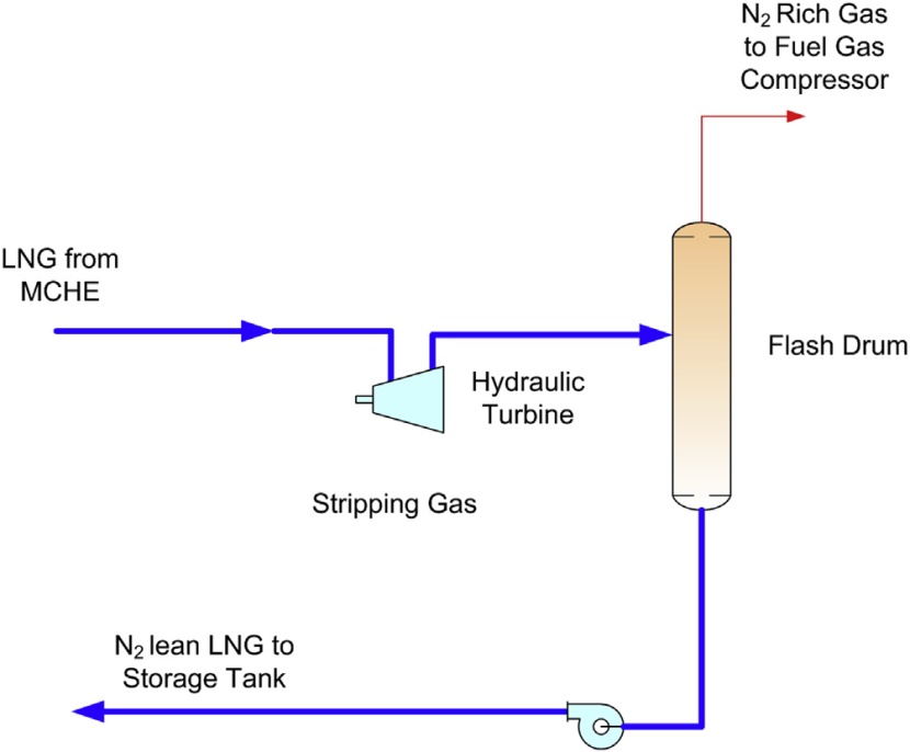
For feed gas containing nitrogen levels of approximately 1 to about 2 mole %, nitrogen can be removed in the end-flash section within an LNG production plant. The LNG from the main cryogenic heat exchanger (MCHE) is letdown in pressure with a hydraulic turbine to flash off the nitrogen content. The flashed liquid, which is reduced in nitrogen content, is pumped to the storage tanks and the flashed vapor (containing high levels of nitrogen) is returned to the fuel gas system by compressing to fuel gas pressure. A typical diagram showing the simple end-flash process is shown in Figure 26.
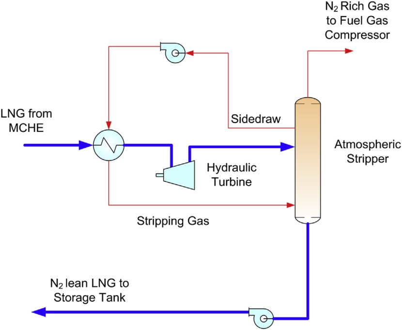
For more efficient nitrogen removal, an atmospheric stripper can be used instead of a flash drum in the end flash process, as shown in Figure 27. The stripper operates at close to atmospheric pressure. To create a stripping gas, a methane rich side stream from the upper section of the stripper can be used. The tray liquid is heated by the LNG from the Main Exchanger and partially vaporized prior to feeding to the bottom of the stripper as a stripping gas. This simple stripping process can offer an efficient nitrogen separation from methane for LNG feed with nitrogen contents up to 5 mole % (Vovard et al., 2011).
Generally the LNG flash gas is used to provide fuel for gas turbines on the LNG plant, but if the amount of nitrogen in the feed gas is high, treatment of flash gas for nitrogen removal may be required since the lean fuel gas may not meet the lower limit of heating value or Wobbe Index specified by the gas turbine manufacturer.
Upstream nitrogen removal processes
Nitrogen can be naturally occurring in high concentration in some fields, and in enhanced oil recovery fields where nitrogen injection is used for oil recovery. The nitrogen content will build up over time, which must be removed to meet the sales gas heating value specification.
When nitrogen is present in high concentrations (greater than 5 mole %), it should be removed in the front section of the LNG plant to minimize liquefaction requirements. There are several processing methods that can be used to remove nitrogen before it enters the liquefaction unit. There are also other options within the LNG technology to remove nitrogen in the liquefaction process.
That’s interesting: https://sea-man.org/personal-protective-equipment.html
Membranes and molecular sieve technology can remove nitrogen but the application is generally limited for small units. Membrane units typically produce a waste nitrogen stream with a fairly high hydrocarbon content that is a revenue loss and cannot be vented directly to the atmosphere. Waste nitrogen must be reinjected for sequestration or disposed by other means. Molecular sieve technology is uneconomical when used to remove high levels of nitrogen. The only viable nitrogen rejection technology is with the use of cryogenic separation (Finn, 2007; Garcel, 2008).
Several cryogenic schemes are known to reject nitrogen from variable-content nitrogen natural gas. Each type of these processes can produce a nitrogen waste stream suitable to meet the EOR requirements. The rejected nitrogen stream usually contains a small quantity of hydrocarbon (pre-dominantly methane). If the nitrogen is reinjected, the hydrocarbon contained in the nitrogen is not lost but becomes deferred revenue. If nitrogen is vented, the hydrocarbon content of the nitrogen vent stream must meet the environmental regulation, typically set at 0.5 to 1 mole % (Millward et al., 2005; Wilkinson and Johnson, 2010). The selection of the Nitrogen Rejection Unit (NRU) process must therefore consider the optimum hydrocarbon recoveries, as well as the utility and capital tradeoffs. If the unit is installed in an existing facility, the design selection must be suitable to be integrated with the existing equipment.
Similar to the LNG plant feed gas, the high boiling materials such as aromatics and CO2 content in the feed gas must be removed to a very low level. There are four generic cryogenic processes for nitrogen removal: Single Column process, Double Column process, Preseparation Column (or Three Column) process, and the Two Column process. These processes vary in complexity and efficiency and are discussed individually in the following sections (MacKenzie et al., 2002).
Single column nitrogen rejection
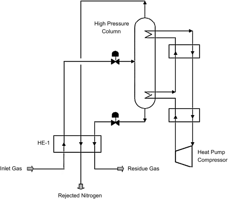
The Single Column process, shown in Figure 28, utilizes a single distillation column typically operating at 300 to 400 psig, operated by a closed-loop methane heat-pump system that provides both the reboiler duty and the condensing duty. In this process, feed gas is cooled in heat exchanger HE-1 using the overhead nitrogen and bottom reboiler methane as the coolants. This method can produce high-pressure rejected nitrogen. The drawback is the high power consumption by the heat pump compressor (Kohl and Nielsen, 1997).
Double column nitrogen rejection
The Double Column process is shown in Figure 29. This process uses two distillation columns operating at different pressures that are thermally linked, where the condenser for the high pressure column is used to reboil the low pressure column. The process provides all the refrigeration for the separation through the Joule-Thompson effect by cascaded pressure letdown of the feed.
The nitrogen is produced at low pressure and vented to atmosphere. The liquid methane product is cryogenically pumped to an intermediate pressure, vaporized in the process, and compressed to pipeline pressure. The process basically fractionates the feed gas stream in the low pressure column, which operates at the cold portion of the NRU, typically at -250 °F to -310 °F, which is prone to CO2 freezing. The CO2 content in the feed gas must therefore be removed to a very low level to avoid freezing in the tower.
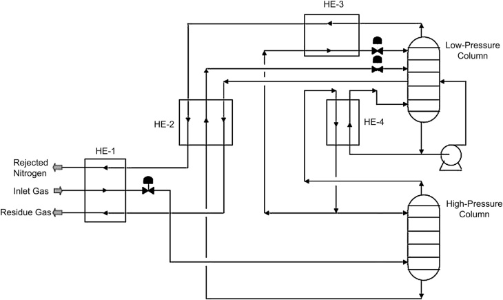
In this process, the feed gas is cooled and partially condensed in heat exchanger HE-1 using the nitrogen vent stream and methane product and fed to a high pressure rectification column, which produces a high purity nitrogen liquid off the top. The bottom product, a mixture of methane and nitrogen, is subcooled in heat exchanger HE-2 and then fed to the low pressure column, which completes the separation.
The overhead product from the high pressure column, relatively pure nitrogen, is condensed in HE-4, which also serves as a reboiler for the low pressure column. A portion of this liquid nitrogen is used as reflux for the high pressure column while the remainder is subcooled in heat exchanger HE-3 and used as reflux for the low pressure column. The methane product from the bottom of low pressure column is pumped, and then heated to ambient temperature in heat exchangers HE-2 and HE-1 (Kohl and Nielsen, 1997).
Three column nitrogen rejection
The Three Column (Preseparation Column) process, as shown in Figure 30, is a variation of the Double Column process where the process is made up of the high pressure column (prefractionator), intermediate pressure column, and the low pressure column. The prefractionator can remove the bulk of the methane and CO2 content as a bottoms product, thereby concentrating the nitrogen content in the overhead. With a lower CO2 content to the cold section, the process is more CO2 tolerant and can operate with a higher CO2 content feed gas with CO2 content up to 1.5 mole %.
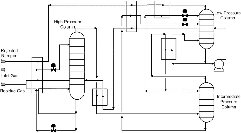
The prefractionator column operates at a higher pressure with temperature ranging between -150 °F and -180 °F, which would avoid any CO2 freezing problem. Removing the bulk of the CO2 from the prefractionator column greatly reduces the CO2 content in the cold end of the NRU, increasing the process tolerance to CO2. This was a very important consideration in the design selection since the streams coming from the NGL plants are already dry and treated for CO2. Additional CO2 removal would add to the capital and operating cost of the project.
Additionally, the heavy hydrocarbons in the feed are recovered in the residue stream from the bottoms of the prefractionator column. This increases the hydrocarbon recoveries and revenues from the NRU.
Two-column nitrogen rejection
The Two Column Process, as shown in Figure 31, is similar to the Three Column process, without the intermediate column. The process comprises a high pressure prefractionator and a low pressure column. Similar to the Three Column design, the prefractionator reduces the CO2 content in the feed gas to the low pressure column and is therefore more CO2 tolerant.
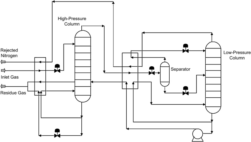
The design of the Two Column process is simpler than the Three Column process. Ifit were used to process a lower nitrogen content gas, the operating pressure of the low pressure column can be increased to reduce energy consumption (MacKenzie et al., 2002).
Nitrogen removal process selection
Process selection for the NRU should be based on operating flexibility, complexity, and sensitivity to feed gas compositions in addition to life cycle costs. The key parameters for process selection are feed gas nitrogen and CO2 contents, feed pressure, flow rate, methane recovery, and contaminant levels. The more important parameter is the CO2 tolerance of the selected process.
Figure 32 shows the methane recoveries of three different processes at various feed nitrogen contents, when the nitrogen waste stream is vented. In summary, for feed gas nitrogen contents below 30 %, the Single Column process is applicable. The Double Column process is applicable when the nitrogen content in the feed gas is above 30 %. For nitrogen content in the feed gas below 50 %, the Two Column process (prefractionator) is the optimum choice (Trautmann et al., 2000).

An important characteristic of NRU is their ability to tolerate the most common impurity in natural gas, CO2. Generally, CO2 tolerance is determined by the coldest spot where CO2 tends to freeze. This is usually a function of the column pressure and nitrogen content in the feed gas. The higher the column pressure the warmer the temperature and the higher the CO2 tolerance.
Startup, transient, and upset conditions also need to be evaluated in determining if CO2 freezing may pose an operating problem. The CO2 tolerance of the process is probably more important in the selection process. A process that has very little CO2 tolerance may require a costly deep CO2 removal system like a molecular sieve whereas a more CO2 tolerant process may require only an amine system. A more CO2 tolerant process is also more reliable, since it can handle CO2 removal upsets and avoid shutdown required for derimming due to a CO2 freezing problem.
Nitrogen removal process integration
As mentioned before, the specific liquefaction power consumption (kW/ton) increases with the nitrogen content in the feed gas. Therefore, there is an economic justification to remove the nitrogen from the feed gas before liquefaction.
When the nitrogen removal is performed within the liquefaction section, it avoids the NRU product compression system (with refrigeration provided by a liquefaction unit refrigeration system) as well as losses associated with reheating and cooling feed gas for nitrogen rejection. However in this scheme, a high level of integration with liquefaction system adds to process complexity and operation risk as neither the NRU nor liquefaction system is conventional.
When nitrogen rejection is to be installed in conjunction with AGRU and NGL recovery, the opportunity exists to integrate both facilities by eliminating repeated heat exchange equipment and recompression. For example, the selection of the NGL unit outlet pressure can be set to match the best efficiency point of the NRU columns, and the rejected nitrogen from the NRU can be reused in stripping in the AGRU section. Such a simple integration concept can be incorporated into the design to achieve higher energy efficiency and reduce equipment counts while maintaining the operability of the overall process design (Trautmann et al., 2000).