The LNG carrier survey plays a crucial role in evaluating the structural integrity and maintenance practices of LNG carriers. Through the LNG carrier survey, experts can identify potential weaknesses and areas for improvement in vessel design and upkeep. This comprehensive LNG carrier survey not only assesses the current state but also provides recommendations for future enhancements. Repeated LNG carrier surveys ensure that all findings are up to date and have been implemented effectively.
Furthermore, the LNG carrier survey is essential for assessing the maintenance schedule and material quality of these specialized vessels. Regular LNG carrier surveys help in predicting potential equipment failures and minimizing downtime. Stakeholders rely on these LNG carrier surveys to make informed decisions regarding repairs and upgrades. By integrating the findings from LNG carrier surveys into operational strategies, the maritime industry can improve the safety and efficiency of LNG transportation. Each LNG carrier survey contributes significantly to the longevity and safety of LNG carrier operations.
Introduction
ABS Rules and Introduction
ABS specific requirements for the surveys on existing gas carriers are in Sections of the Rules. The Working Instructions SWZ-002-05-P05 Rev.12 is relative to the surveys to be carried out in connection with the issue, periodical surveys and renewal of the Certificate of Fitness.
The emergence of LNGC’s in the recent past has predicated the need for concize Rules and Survey requirements. With this in mind, the LNG Focus Group of ABS has initiated a general review of the Gas Carrier Rules and Instructions as a dedicated project in order to provide the most comprehensive, yet risk appropriate Rules and Instructions to meet the expectations of today LNGC Owners and Operators.
Specific Survey Requirements for LNG Carriers
A Key Systems for LNG Carriers Containment and Safety: Design and OperationLNG carrier is to be considered as a “tanker“, as described by conventional terms. However, LNGC is not subject to enhanced survey requirements, mainly due to the lack of tank internal structures and the characteristics of the transported cargo.
The specific requirements for LNGC’s in the Rules are in addition to and in no way a replacement for the standard requirements of periodic surveys for existing tankers.
Drydock Surveys
There is no difference between the drydock survey of a LNG carrier and the drydock survey of any other type of tanker. Items to be surveyed are:
- Hull conditions.
- Bilge keels.
- Rudder (see Figure 1).
- Sea chests.
- Propellers and stern seals (see Figure 1).
- Hull appendages.
- Fastening of gratings.
- Chain cables.
- Bow thruster.

Cargo Containment System
The extent and scope of cargo containment surveys differ depending on whether the vessel is membrane or Independent Cargo Tanksindependent tank type and wheteher the survey haqs to comply with annual, intermediate or special survey.
A) MEMBRANE TYPE SHIPS
The scope of inspection of a membrane tank includes:
- assessment of condition and integrity of the primary membrane, by visual examination;
- assessment of condition and integrity of piping and equipment inside the tank and in particular of the pump tower and cargo pumps;
- assessment of condition and integrity of the secondary barrier as well as of the interbarrier space and insulation space insulation. Of course this assessment can only be done by indirect methods, due to inaccessibility of these spaces;
- assessment of the condition of the inner hull.
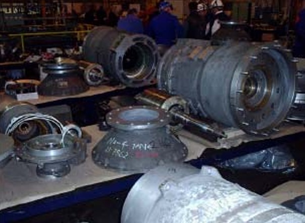
Figures 2 and 3 show the inspection of cargo pumps inside a cargo tank during Special Survey N.1 of a LNG carrier with MARK III insulation systrem.
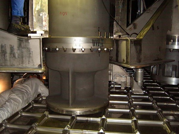
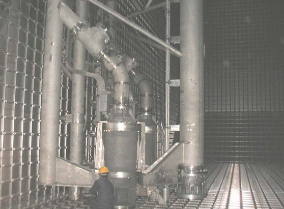
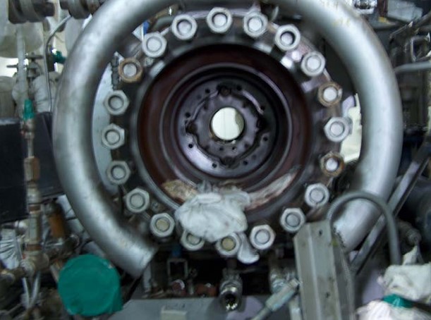
Figure 4 shows th foot valve for the emergency pump.
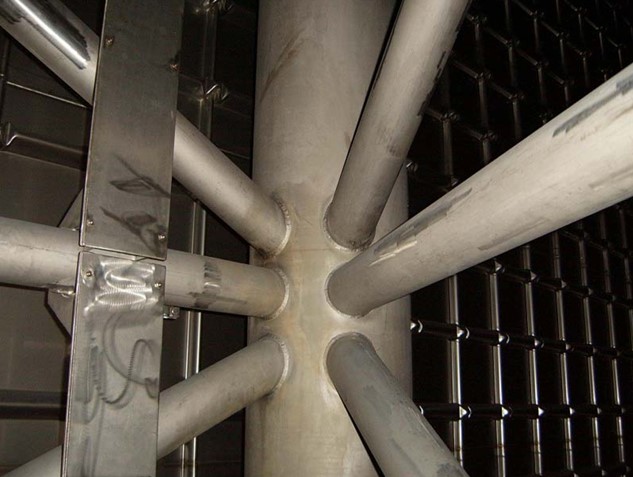
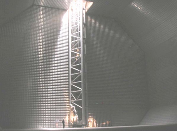
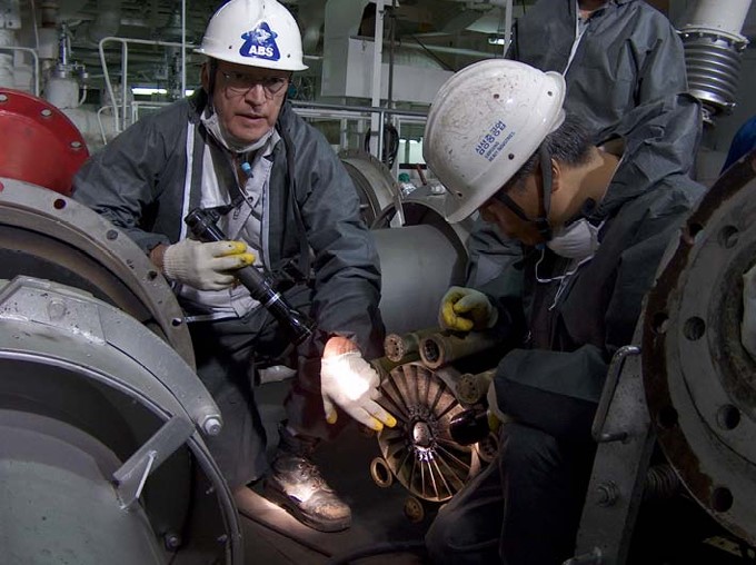
Figures 5, 6 and 7 show details of the pump tower.
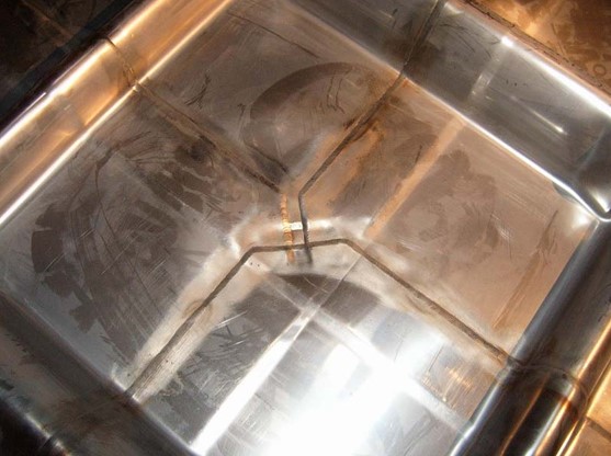
Figures 8 and 9 details of the primary membrane.
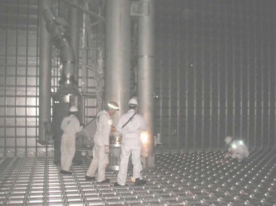
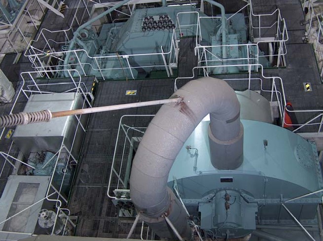
Finally Figure 10 shows a general view of the cargo tank during the survey.
The secondary membrane, insulation space and interbarrier space are assessed by a global test of the membranes. Table below summarizes a typical test procedure.
| Membrane Test | |||
|---|---|---|---|
| TESTED ITEM | PRIMARY BARRIER PRESSURE | SECONDARY BARRIER PRESSURE | TEST PROCEDURE |
| Primary Membrane | – 800 mbar | – 800 mbar | 1) Hold 24 hours and monitor. 2) Bring both spaces to atmospheric pressure. 3) Inject nitrogen in both spaces under controlled conditions. |
| Secondary Membrane | Atmospheric pressure | Steady at -530 mbar, then increase pressure and record decay from -430 and -300 mbar | 1) Inject nitrogen in the primary space until the pressure of the secondary barrier is -530 mbar. 2) Close and lock all the valves. 3) Monitor the decay without further injection of nitrogen. 4) Inject nitrogen to bring the space at the atmospheric pressure. |
B) MOSS ROSENBERG CARGO CONTAINMENT SYSTEM
The scope of inspection of a Moss-Rosenberg tank includes:
- examination of the insulation;
- examination of the tank critical points (connection with dome);
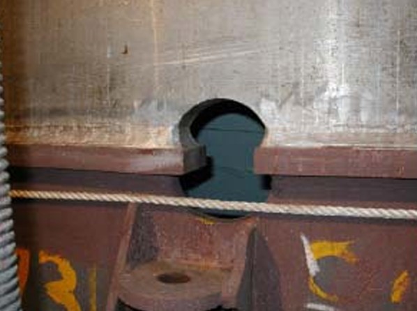
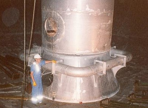
- examination of the tank supporting skirt with particular attention to the structural transition joint;
- examination of the skirt foundation;
- examination of the secondary barrier (drip tray);
- examination of the pump tower, its connection to the dome and its support at the bottom of the tank.
Figure 11 shows the parts to be inspected that are typical Moss-Rosenmerg ships.
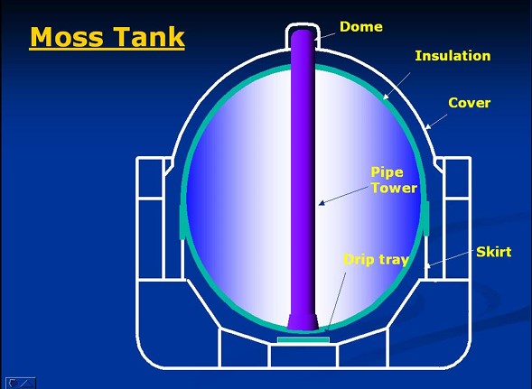
Figure 12 is a sketch showing how a typical transition joint is fabricated.

Figure 13 is picture is a transition joint as it can be seen during the survey.
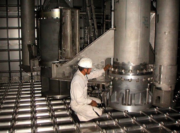
Figures 14 shows the the tower sliding shoe.
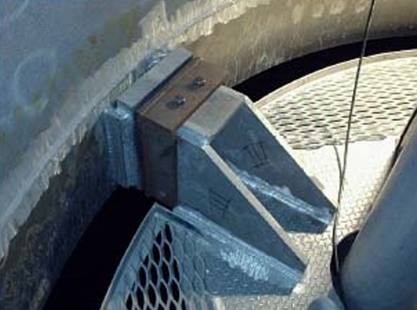
Figure 15 the pipes inside the pump tower.
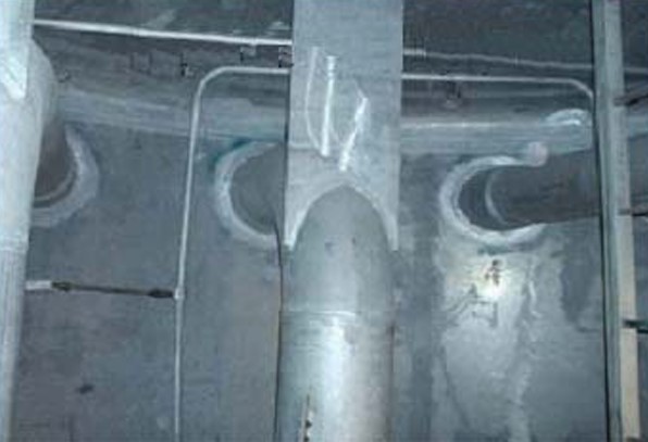
Figure 16 the lower portion of the tower.
Note that it is not possible to hydrotest tanks designed for carriage of LNG, as they are designed for a cargo that has a density of less than one half of that of water. If the tank is hydrotested, it would be overstressed. For this reason, the suitable applicable test is the hydropneumatic test, which is carried out by filling the tank up to about one half of its depth and pressurizing the remaining part of the tank up to the MARVS pressure. This is also valid for independent prismatic tanks.
Cargo Handling Systems
The scope of inspection of LNG Cargo Handling Systems and Their Operationscargo handling system includes:
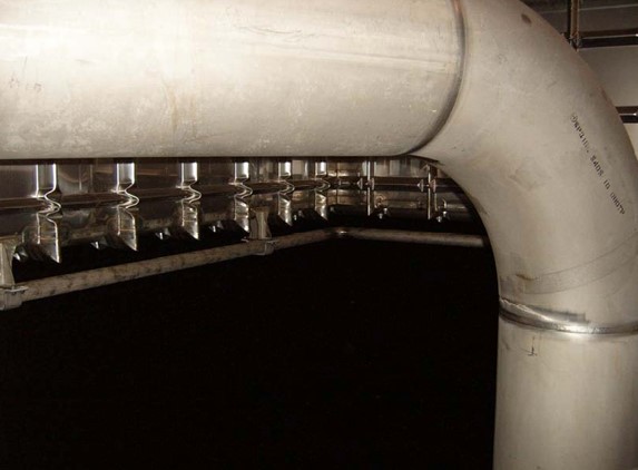
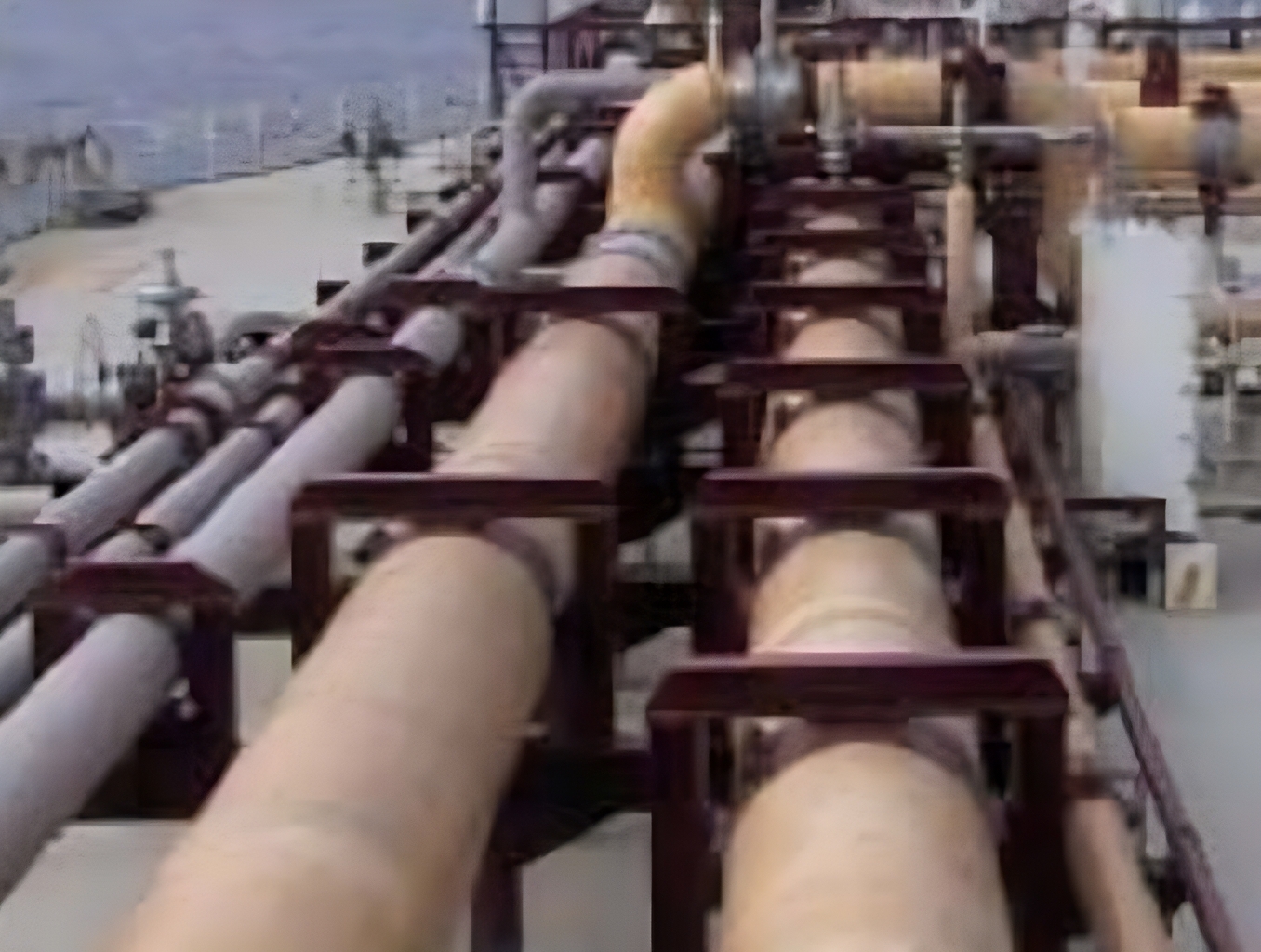
A) CARGO PIPING
- cargo piping insulation;
- cargo pipe supports and clamping systems;
- expansion joints;
- flanges and valves;
- cargo piping bonding systems;
- cargo manifolds;
- drip pans;
- gratings and sheetings.
Figure 17 shows details of cargo piping.
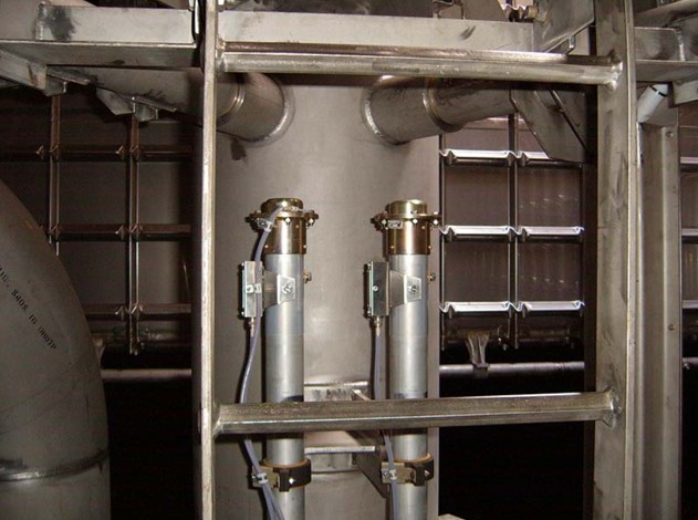
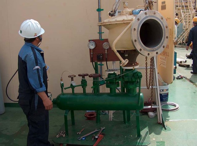
B) SAFETY VALVES
- cargo tank safety valves;
- interbarrier spaces safety valves;
- cargo pipe safety valves;
- cargo pipe safety valves;
- safety valves and venting line draining systems;
- cargo masts.
Figure 18 shows a safety valve ready for inspection.
The scope of inspection of cargo handling system includes:
C) CARGO HANDLING EQUIPMENT
- cargo pumps;
- heavy duty compressors;
- low duty compressors;
- vaporizers;
- heaters;
- inert gas generators.
Figures 19 and 20 show Use of Cargo Pumps on Liquefied Gas Carrierscargo pumps opened out for inspection.
Figures 21 and 22 show cargo compressors.

Propulsion
Propulsion equipment and systems should not be considered particular to LNGC’s. Due to increased thermal efficiency of slow speed diesel propulsion plants, today’s LNGC’s are the only steam propelled vessels under construction today. However, starting from next generation, also the LNGC’s will abandon the steam.
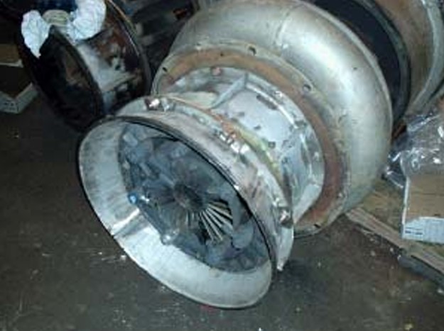
Figures 23 shows a turbine still closed.
Figures 24 and 25 show an open turbine (ahead and astern).
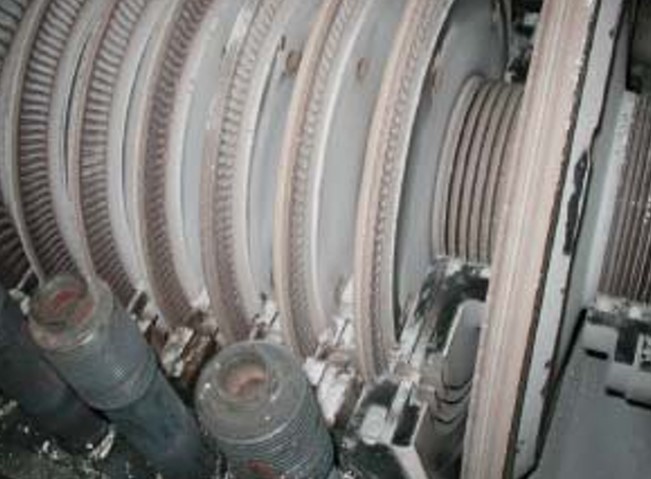
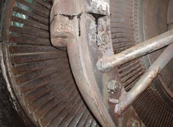
Figure 26 shows open pinion gears.

Figures 27 shows an opened condenser.
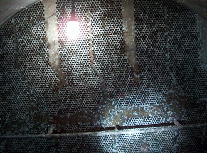
Figure 28 shows the inside of a main boiler during the inspection.
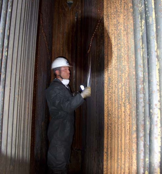
Figure 29 is a burner register.
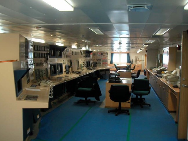
Control and Safery Systems
All control and safety systems are to be examined at all annual and intermediate surveys. Figure 30 shows a control station.
Electrical Equipment
All electrical equipment and apparatus in hazardous areas are to be checked as indicated above.

- The Society of International Gas Tanker and Terminal Operators (SIGTTO). Liquefied Gas Handling Principles on Ships and in Terminals (LGHP4) / 4th Edition: 2021.
- The international group of liquefied natural gas importers (GIIGNL). LNG custody transfer handbook / 6th Edition: 2020-2021.
- American Gas Association, Gas Supply Review, 5 (February 1977).
- ©Witherby Publishing Group Ltd. LNG Shipping Knowledge / 3rd Edition: 2008-2020.
- CBS Publishers & Distributors Pvt Ltd. Design of LPG and LNG Jetties with Navigation and Risk Analysis / 4th Edition.
- NATURAL GAS PROCESSING & ITS ENERGY TRANSITION ROLE: LNG, CNG, LPG & NGL Paperback – Large Print, November 14, 2023.
- American Gas Association, Gas Supply Review, 5 (February 1977).
- The Society of International Gas Tanker and Terminal Operators (SIGTTO). Ship/Shore Interface / 1st Edition, 2018.
- Department of Transportation, US Coast Guard, Liquefied Natural Gas, Views and Practices Policy and Safety, p. IV-3.
- Department of Transportation, US Coast Guard, Liquefied Natural Gas, Views and Practices Policy and Safety, p. IV-4.
- Federal Power commission, Trunkline LNG Company et al., Opinion No. 796-A, Docket No s. CP74-138-140 (Washington, D. C.: Federal Power Commission, June 30, 1977).
- Federal Power Commission, Final Environmental Impact Statement Calcasieu LNG Project Trunkline LNG Company Docket No. CP74-138 et al., (Washington, D. C.: Federal Power Commission, September 1976).
- Federal Power Commission, «FPC Judge Approves Importation of Indonesia LNG».
- OCIMF, ICS, SIGTTO & CDI. Ship to Ship Transfer Guide for Petroleum, Chemicals and Liquefied Gases / 1st Edition, 2013.
- Federal Power Commission, «Table of LNG imports and exports for 1976», News Release, June 3, 1977, and Federal Energy Administration, Monthly Energy Review, March 1977.
- Office of Technology Assessment LNG panel meeting, Washington, D. C., June 23, 1977.
- Socio-Economic Systems, Inc., Environmental Impact Report for the Proposed Oxnard LNG Facilities, Safety, Appendix B (Los Angeles, Ca.: Socio-Economic Systems, 1976).
- «LNG Scorecard», Pipeline and Gas Journal 203 (June 1976): 20.
- Dean Hale, «Cold Winter Spurs LNG Activity»: 30.