LNG Electrical Equipment for Hazardous Areas is specifically designed to operate safely in environments with flammable gases and vapors, complying with strict international standards. These devices feature intrinsic safety, explosion-proof enclosures and non-incendive designs to prevent ignition.
- LNG Terminal Electrical Safety Equipment
- Classification of Certified Safe-Type Equipment
- Explosion Proof Equipment (Ex d)
- Increased Safety Equipment (Ex e)
- Intrinsically Safe Equipment (Ex i)
- Oil Immersion Equipment (Ex o)
- Pressurized Apparatus (Purged Apparatus) (Ex p)
- Powder Filled Equipment (Ex q)
- Encapsulated Equipment (Ex m)
- Non Sparking Equipment (Ex n)
- Special Type Equipment (Ex s)
Such equipment is engineered to withstand harsh conditions, including extreme temperatures and corrosive atmospheres, ensuring durability and reliability in LNG facilities. Regular maintenance and inspection are essential to maintain their safety and efficiency.
LNG Terminal Electrical Safety Equipment
Classification of Certified Safe-Type Equipment
In hazardous areas electrical equipment should be reduced to a minimum, nothing more than to those strictly necessary. In any case all the electrical equipment in hazardous areas are to be certified safe-type equipment.
Certified safe equipment is equipment intended for installation in hazardous areas, where flammable or explosive gases, vapors, or dust are normally or likely to be present. The equipment is to be type-tested and certified by a competent, independent testing laboratory for compliance with IEC Publication 60079 or equivalent standard, and rated according to its enclosure and Flammability, Explosion and other Hazards of Liquefied Gastypes of flammable atmosphere in which it is safe to install.
There are several different types of certified safety equipment depending on their construction and on the grade of safety they offer and hence their suitability for use in installation in hazardous areas. Table 1 lists all types of certified-safe equipment and indicates the zones where they can be used.
| Table 1. Certified-safe equipment | ||
|---|---|---|
| SYMBOL | TYPE | ZONE |
| Ex d | Explosion proof (enclosure) | 1, 2 |
| Ex e | Increased safety | 1, 2 |
| Ex ia | Intrinsically safe | 0, 1, 2 |
| Ex ib | Intrinsically safe | 1, 2 |
| Ex o | Oil immersion | 2 |
| Ex p | Pressurized apparatus (purged) | 1, 2 |
| Ex q | Powder filling (sand filling) | 2 |
| Ex m | Encapsulation | 1, 2 |
| Ex n or Ex N | Non sparking circuit | 2 |
| Ex s | Special type | – |
Explosion Proof Equipment (Ex d)
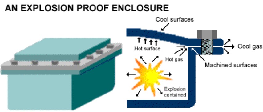
Explosion proof equipment (Flame proof in UK and Pressure-Proof in Germany) is one which possess an enclosure capable of withstanding, without damage, an explosion of a prescribed flammable gas or vapor within the enclosure and prevent the transmission of flame or sparks which would ignite the external prescribed flammable gas or vapor for which it is designed, and which normally operates at an external temperature that will not ignite the external prescribed flammable gas or vapor. An explosion proof enclosure may not necessarily or ordinarily be weatherproof or dustproof (See Figure 1).
The equipment is selected, installed, operated and maintained within the acceptable ratings. The maintenance and use of Ex d equipment are under responsibility of the crew.
The electric circuit of an Ex d equipment should include all required protection devices.
If flammable gases/vapors present in atmosphere can enter the enclosure, sparking which will ignite a flammable gas or vapor, may occur at any part of the equipment contained in the enclosure in normal operation due to an internal fault due to insulation failure, etc. Of course, this event would generate an explosion and therefore means are to be provided to avoid any possibility of flammable gas/vapor entering the enclosure.
From the construction point of view an explosion proof equipment enclosure should have the following characteristics:
- approved material without use of frictional sparking items;
- capability to withstand rough usage;
- strength adequate to withstand all required tests;
- effective threaded metal to metal joints with a minimum of 5 full uninterrupted engaged threads and a minimum effective uninterrupted axial length of threaded engagement of 9 mm;
- no intentional gap should exist between joining surfaces;
- no packing material is to be used to form an explosion proof joint. If compressible packing material or gaskets are necessary to seal a joint to obtain the required protection class (IPxx), the packing is to be included as an addition, but is not to be included in the explosion proof joint. Additionally, any displacement, integration or omission of such a packing (gasket) is not to impair How to Prevent Fire and Explosion or How to Minimize Effects of itthe explosion proof behavior of the joint.
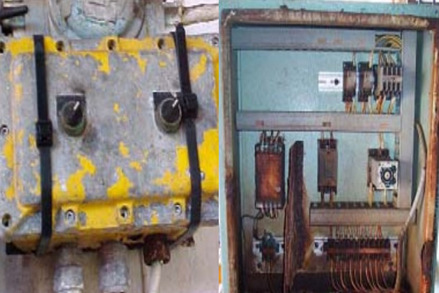
Figure 2 shows an Ex d enclosure after an internal fire.
Increased Safety Equipment (Ex e)
Increased safety equipment is designed with a method of protection in which measures additional to those adopted on ordinary industrial practice are applied, so as to give increased security against the possibility of excessive temperatures and the occurrence of arcs or sparks in electrical apparatus, which does not produce arcs or sparks in normal service.
In order an equipment may satisfy the requirement to be classed as Ex e, construction methods more accurate than those used for normal equipment are used to ensure that no sparks and excessive temperature be produced. This is obtained with:
- careful terminal design;
- use of good quality insulation material;
- use of special materials to protect the enclosure against impact, ingress of dust and moisture.
Intrinsically Safe Equipment (Ex i)
Intrinsically safe equipment is defined as “equipment and wiring which is incapable of releasing sufficient electrical or thermal energy under normal or abnormal conditions to cause ignition of a specific hazardous atmospheric mixture in its most easily ignited concentration.”
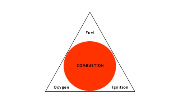
In order to have a fire or explosion, fuel, oxygen and a source of ignition must be present (see Figure 3).
An intrinsically safe system assumes the fuel and oxygen is present in the atmosphere, but the system is designed so the electrical energy or thermal energy of a particular instrument loop can never be great enough to cause ignition.
In fact, the intrinsic safety concept was developed in the early 1900s as the result of a methane explosion in a mine that killed a large number of people. The intrinsically safe methodology operates by preventing sufficient energy from being available under normal or abnormal conditions to serve as an ignition source. As a result, there are natural limitations on the types of electrical equipment that can be intrinsically safe. Electrical equipment, such as pump motors, that requires energy levels above the intrinsically safe level cannot use this method.
Intrinsically safe equipment is designed for the worst case, which would be to assume the explosive atmosphere is always present and the electrical or thermal energy is the lowest required to cause a fire or explosion.
Read also: Effects and Risks of Underwater Explosion for Gas Carriers
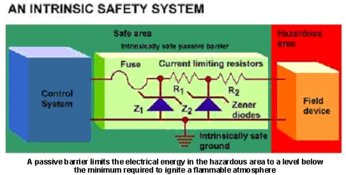
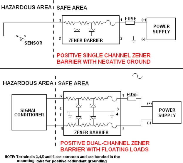
The basic design of an intrinsic safety barrier uses Zener Diodes to limit voltage, resistors to limit current and a fuse (see Figure 4).
Equipment, which has been designed for and is available for use in hazardous areas with intrinsically safe barriers includes:
- 4-20 mA dc Two Wire Transmitters.
- Thermocouples.
- RTDs.
- Strain Gages.
- Pressure, Flow & Level Switches.
- I/P Converters.
- Solenoid Valves.
- Proximity Switches.
- Infrared Temperature Sensors.
- Potentiometers.
- LED Indicating Lights.
- Magnetic Pickup Flow-meters.
Products to be mounted in the hazardous area can be approved either under the LOOP (also denominated SYSTEM) or ENTITY approval concept.
The LOOP (or SYSTEM) concept specifies the exact part number and products that can be used in the loop. No deviation from the specified units is allowed.
The ENTITY concept specifies parameters which any approved intrinsic safety barrier must meet. This allows the user to select barriers from different approved manufacturers. Under entity approval two items may be interconnected if the conditions stated in Table 2 are met.
| Table 2. ENTITY concept parameters | |||
|---|---|---|---|
| HAZARDOUS AREA | SAFE AREA | ||
| Intrinsically Safe Approved Apparatus | Intrinsically Safe Barrier | ||
| Vmax | < | Voc | |
| Imax | < | Isc | |
| La | > | Li + Lw | |
| Ci | > | Ci +Cw | |
| Vmax = Maximum open circuit voltage Voc = Maximum open circuit voltage (barrier) Imax = Maximum short circuit current Isc = Maximum short circuit current (barrier) La = Maximum allowed inductance (barrier) Li = Maximum unprotected inductance Lw = Inductance interconnecting wiring Ca = Maximum allowed capacitance (barrier) Ci = Maximum unprotected capacitance Cw = Capacitance of interconnecting wiring | |||
In all cases the intrinsically safe barriers and equipment must be wired as per an approved drawing. Capacitance and inductance of the wiring and cables must be included in the loop evaluation (see Figure 5).
Intrinsic safety systems in Europe are different than in U. S.
In Europe, there are two varieties of intrinsic safety systems: Ex ia and Ex ib. Ex ia systems are considered safe under two independent fault conditions while Ex ib systems are considered safe under one independent fault condition. Only Ex ia is allowed in Zone 0 hazardous locations.
For intrinsically safe equipment/circuit EX ib the following limitations are acceptable.
Ex ib equipment should be incapable of causing ignition in normal operation, with a single fault and with the following safety factors:
- -1,5 in normal operation and with one fault;
- -1,0 with one fault, if the equipment contains no unprotected switch contacts in parts likely to be exposed to a potentially explosive atmosphere and the fault is self-revealing.
U. S. and Canadian intrinsic safety systems have only one type, which is equivalent to Ex ia. Intrinsic safety codes also allow certain devices, called simple apparatus, to be considered intrinsically safe without approval or certification. These devices cannot generate or store more than 1,2 V, 0,1 A, 0,25 mW, and 20 µJ. Some such devices are thermocouples, switches, resistance temperature detectors (RTDs), and light-emitting diodes (LEDs). Intrinsically safe circuits must be approved for the hazardous location where they are used.
Oil Immersion Equipment (Ex o)
The equipment or its parts are immersed in oil in such a way that an explosive atmosphere, which may be above the oil or outside the enclosure, cannot be ignited.
Oil used is mineral oil conforming to relevant standards.
The main constructional features are:
- fully enclosed, leak-proof enclosure;
- oil level indicator.
In general this type of protection is used for transformers, switchgears and control gears.
Pressurized Apparatus (Purged Apparatus) (Ex p)
A pressurized apparatus is a type of protection by which the entry of surrounding atmosphere into the enclosure of the electrical apparatus is prevented by maintaining inside the enclosure, a protective gas at a higher pressure than that of the surrounding atmosphere.
There are two types of pressurized apparatus depending on how the higher pressure inside the apparatus enclosure is kept:
1) DYNAMIC PRESSURIZATION
Dynamic pressurization or pressurization by continuous circulation of protective gas (purging) is a method of maintaining pressure in an enclosure in which after purging the protective gas is passed continuously through the enclosure at a pressure above that of the specified minimum and discharged to the outside atmosphere.
2) STATIC PRESSURIZATION
Static pressurization is a continuous pressurization with leakage compensation. The leakage is compensated by air supplied and pressurized continuously from a non-hazardous area to avoid ingress of flammable gases/vapor inside the enclosure.
Powder Filled Equipment (Ex q)
The equipment enclosure is filled with quartz/sand so that in normal operating condition, any arc occurring within the enclosure of electrical equipment will not ignite the surrounding atmosphere.
The main enclosure constructional features are:
- high mechanical strength;
- ingress protection;
- powder filled;
- insulation of enclosed equipment.
Encapsulated Equipment (Ex m)
Encapsulated equipment are factory sealed equipment, such as portable lamps and gas detectors.
Non Sparking Equipment (Ex n)
Non sparking equipment have a type of protection applied to an electrical apparatus such that, in normal operation, it is not capable of igniting a surrounding explosive atmosphere, and a fault capable of causing ignition is not likely to occur.
Main characteristics of non sparking equipment are:
- hermetically sealed type;
- restricted breathing type;
- careful design of terminals.
Special Type Equipment (Ex s)
Special type equipment are specially designed equipment that do not use any of the previous systems for assuring their suitability in hazardous areas.
This category has been established to permit the research and the introduction of new features in the market.

