Dive into the intricate workings of LNG reliquefaction plant with our comprehensive guide. Explore key components like the reliquefaction system, Methane Refrigeration System (MRS-F), and Gas Combustion Unit (Oxidiser).
Gain a thorough understanding of how these systems work together to ensure efficient LNG handling and storage.
Reliquefaction system
Reference: SIGTTO “LNG Shipping Suggested Competency Standards”, Sections:
1 Have an awareness of their purpose and operating principles.
2 Know and understand the principles, operating parameters and limitations.
In the cargo tanks of an LNGC, the cargo is maintained in the liquefied state at a temperature of – minus 161,5 °C (-161,5 °C).
Despite the highly efficient insulation, there is inevitably some warming up during transportation and gas will naturally evaporate from the cargo. This is either consumed on board for propulsion and/or power generation or it has to be reliquefied and returned to the cargo tanks.
Reliquefaction makes it possible to deliver the full amount of loaded LNG to the discharge port, which, if the voyage economics are suitable, can be more profitable than consuming it on board.
Use of a Birth of the Reliquefaction, Design and Operation of the Reliquefaction LPG Plantreliquefaction plant has the potential to deliver the following benefits:
- an increase in the cargo quantity delivered;
- reduced heel required on ballast voyage;
- allows tanks and lines to be pre-cooled prior to arrival at the load port, with comparatively small heel retention.
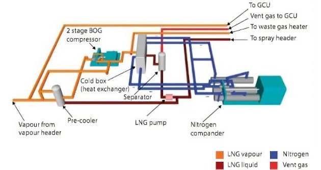
The LNG reliquefaction plant process is typically as follows:
- BOG is removed from the cargo tanks by means of two conventional BOG (LD) compressors (the LD compressor capacity is adjusted automatically in accordance with the boil-off rate);
- the BOG is cooled and condensed to LNG in a cryogenic heat exchanger, or “cold box” (the cryogenic temperature inside the cold box is produced by means of a nitrogen compression/expansion cycle);
- non-condensibles, mainly N2 are removed into a separator tank and vented to atmosphere;
- from the separator (LNG drain tank), the LNG is forced or pumped back to the cargo tanks.
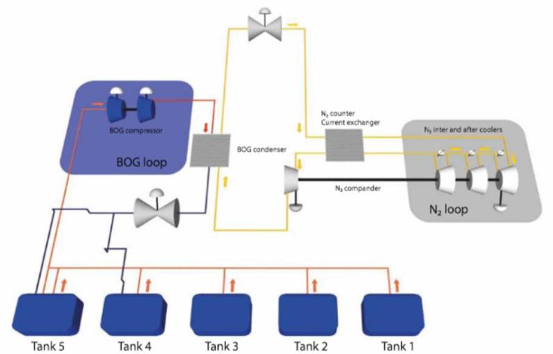
A reliquefaction system has two (2) main process loops:
- Boil off gas loop (BOG loop) – requires, subject to system design, 1,5 to 2 hrs to ramp up/down to full capacity.
- Nitrogen loop (N2 loop): cooling medium – requires, subject to system design, 4 to 5 hrs to reach standby state.
Reliquefaction system overview (N2 “Reverse Brayton Cycle”)
What is Reverse Brayton Cycle?
This is a closed loop refrigeration cycle using N2 as the refrigerant gas.
Systems available include:
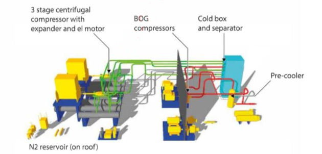
1 Hamworthy “Mark I” system:
- two stage cryogenic BOG compressor, with precooler;
- requires LNG for precooler to start reliquefaction process;
- must be started prior to cargo stripping to remain running;
- if stopped for the closing CTMS it may not be able to restart.
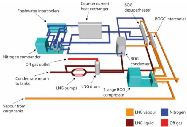
2 Hamworthy “Mark III” system:
- three stage ambient BOG compressor, with preheater.
3 Cryostar “Eco-rel” system:
- two stage ambient BOG compander, with preheater.
Note: the Hamworthy Mark III and Cryostar Eco-rel systems do not require LNG to start the reliquefaction process.
The Cryostar “Eco-Rel” system is shown in Liquefied Natural Gas Tank Protection“Tank top, with cargo pipes and valves”, and is designed for full reliquefaction of BOG containing up to 20 % mol nitrogen in BOG. For higher nitrogen content, partial reliquefaction has to be applied.
Methane Refrigeration System – Full Reliquefaction (MRS-F)
As an alternative, and relatively recent addition to the reliquefaction market, there is now also the methane refrigeration system (MRS-F) full reliquefaction process, developed and patented by DSME.
MRS-F is a full reliquefaction system that is utilised in combination with the fuel gas supply system (FGSS). It is composed of a partial reliquefaction system (PRS) and a methane refrigeration system (MRS) independent cycle, which occurs in series.
An advantage of this system is that, unlike conventional reliquefaction systems that make use of N2 as a means of reliquefying the BOG, the MRS system utilises the vapour from the cargo itself. This leads to a simpler and more economical system. The system can be utilised in both partial reliquefaction mode (PRS mode) and in full reliquefaction mode (MRS mode):
- there are no restrictions on thermal gradient, so the system can be started/stopped immediately;
- the system adopts cargo vapour as the refrigerant medium, rather than N2, so simplifies the system and hardware requirements.
The MRS-F system has primarily been developed for use on ships equipped with SSD propulsion, such as ME-GI and X-DF.
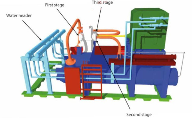
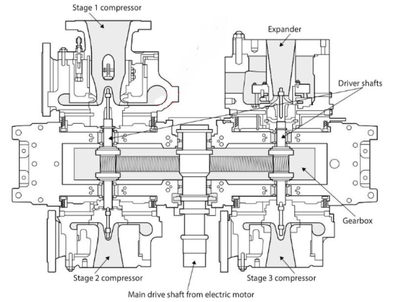
BOG is recirculated via a “closed loop” in series with a fuel gas (FG) compressor to an expander-compressor, and a printed circuit heat exchanger (PCHE).
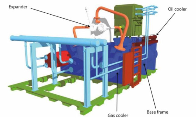
The BOG extracted from the cargo tanks is compressed via a secondary FG compressor and booster compressor. The compressed BOG is precooled to approximately minus 90 °C (-90° C), then subcooled to approximately minus 150 °C (-150 °C).
This sub-cooled BOG will then be expanded, reliquefied in a liquid/gas separator and the BOG condensate returned to the cargo tank(s).
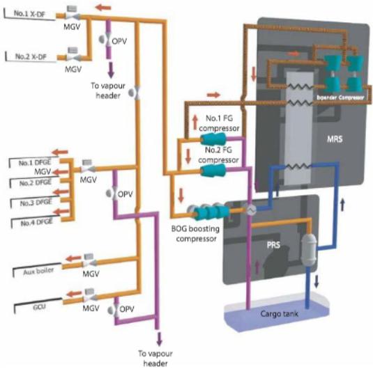
When the ship is idle/at anchor with no propulsion engines in operation, the MRS-F mode is adopted, which allows control of cargo tank pressure.
Gas Combustion Unit (Oxidiser)
Reference: SIGTTO “LNG Shipping Suggested Competency Standards”, Sections:
1 Have an awareness of their purpose and operating principles.
A gas combustion unit (GCU) provides an environmentally friendly solution for excess BOG combustion on LNG carriers, when the boil-off gas cannot be used for reliquefaction (or propulsion), or in an emergency if the reliquefaction plant is unavailable. The GCU is a secondary means of handling boil-off gas from the ship.
Either of the Low Duty Compressor(s) on the Liquefied Natural Gas CarriersLD compressors can individually feed the GCU.
The unit comprises of a gas burner, usually of the “swirl” type, and a specially designed combustion chamber. The unit is usually sited in the ship’s funnel and operation is usually fully automatic and integrated with the ship’s IAS.
Typical capacity range: 0,5 up to 7,5 tonnes/h methane.
Regasification Plant
Reference: SIGTTO “LNG Shipping Suggested Competency Standards”, Sections:
1 FSRU Operations.
The LNG regasification process uses either a purpose built floating storage regasification unit (FSRU) or a converted LNG carrier with an onboard LNG regasification (regas) plant. Some use a turret mooring facility to connect to a subsea pipe connection offshore, others are moored alongside a shore receiving facility.
While included in the SIGTTO guidelines, FSRU operations, including regasification plants, are outside the scope of this publication. Please refer to Chapters 4 and 5 of SIGTTO “Liquefied Gas Handling Principles on Ships and in Terminals (LGHP4)” for further information.