Explore the critical aspects of gas tank protection on LNG carriers with our comprehensive guide. Learn about essential devices and systems including cargo tank, line, and space protection mechanisms, as well as liquid and vapor valves.
Ensure the safety and integrity of cargo operations with expert insights and best practices.
Cargo Tank Protection Devices
Reference: SIGTTO “LNG Shipping Suggested Competency Standards”, Sections:
1 Have an awareness of their purpose and operating principles.
2 Know and understand their principles, operating parameters and limitations:
- design features;
- use of setters to adjust operating pressure.
3 Know and understand the problems that can occur with cargo tank relief valves.
To protect cargo containment systems from harmful overpressure or under pressure, Chapter 8 of the IGC Code requires that pressure relief systems are fitted. Under 8.2.1 it states that cargo tanks must be fitted with a mini mum of two pressure relief valves (PRVs) of equal size. Additionally, 8.2.2 states that interbarrier spaces must be provided with relief devices.
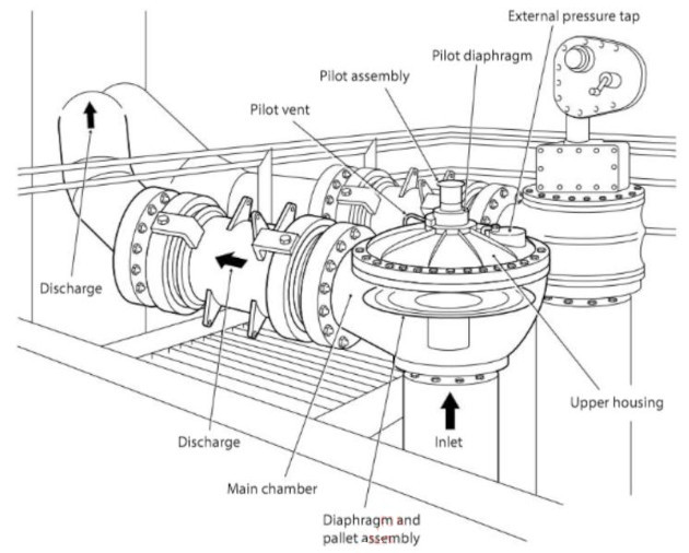
Relief valves are pilot operated to ensure accurate operation at low temperatures and to prevent the main relief valve becoming blocked with ice at the time of relief, making it incapable of reseating.
A pilot operated PRV consists of a main valve and a pilot valve. The main valve has an unbalanced piston or diaphragm.
Pilot valves operate by a pilot spring or, in certain cases, by the adjustment of the set pressure and the blow-down pressure.
Tank pressure is applied to the top of the piston or diaphragm via the pilot. Pressure is defined as force divided by area (kg/cm2, lbs/in2).
As the area at the top of the piston or diaphragm is larger than the bottom, the valve remains closed due to the greater force acting on it. When the set pressure is reached the pilot valve opens, venting the space above the piston to atmosphere or the vent stack, and al lowing the force on the bottom of the piston or diaphragm to open the valve and vent to atmosphere.
When the maximum pressure allowed in the tank is reached, the pilot valve opens and releases the counter pressure that keeps the relief valve in the closed position.
Pilot operated PRVs:
- for the valve to open, the pilot valve must de-pressurise the cavity on the top side of the piston to a pressure equal to 50 % of the inlet pressure;
- when that occurs, the forces are in balance and the valve is on the threshold of opening;
- the piston will then move upwards and the pressure will remain constant during this period;
- when the pilot closes the top cavity is re-pressurised and the piston closes.
Note: The pressure is the same on the PRV on both sides of the diaphragm (i. e. the red/green curve as shown in graph Use of Cargo Pumps on Liquefied Gas Carriers“Pump characteristic curve”). However, while both sides are exposed to the same pressure, the area on the top of the diaphragm, which is holding it closed, is 2-3 times larger than the bottom area that tends to open to lift the diaphragm.
Therefore, it must follow that the force on the top of the diaphragm that is holding it sealed must be 2-3 times greater than the force beneath it.
The cargo tanks must also be protected under vacuum conditions. If the pressure in the tank falls below a set vacuum value, the diaphragm will open and allow atmosphere to flow into the tank.
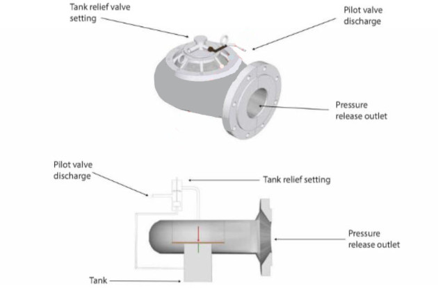
The cargo tank relief valves are fitted at the top of each tank dome and vent to their associated vent mast riser. The relief valves are of the pilot operated relief valve (PORV) type. A cargo tank pressure sensing line relays the pressure directly to the PORV and, in this manner, accurate operation at the low pressures prevailing inside the tank are maintained. Initially, the manufacturer sets up the cargo relief valves to the requirements of the ship. When overhauled, safety valves must always be inspected and reset to their original settings (always check the manufacturer’s instructions).
Typical cargo tank safety valve operation
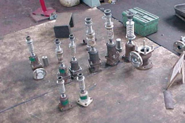
The piston or valve seating is accomplished through the pressure exerted, by a coil spring, onto the top of the piston or valve.
As the tank pressure increases, the valve seating contact force is reduced, making the setting of an exact set pressure more difficult to accomplish. This is particularly true at low pressures.
The opening of the valve and the amount of opening depends, therefore, on the compression of the spring. Any pressure due to flow downstream of the PRV will also tend to close the valve.
The operation and maintenance of the valve is simpler than for the pilot valve type, but it has the disadvantage that, in general, it cannot be set as accurately.
Chattering
This is generally caused by the PRV being incorrectly sized for the tank that it is allocated to, i. e. the PRV was sized for a larger tank and, as a result, the medium being released is insufficient to hold the relief valve open for a sustained period and it regularly relieves, or “chatters”. This is a design problem and would normally be rectified early in the ship’s life. However, chattering can also be caused by excessive back-pressure in the discharge pipe and can also be encountered if valves are placed on a test rig where the volumetric capacity of the rig is too small for the valve being tested. Excessive chattering will cause significant seat damage.
Continued leakage after operation
This is normally the result of dirt being carried over with the process vapour and becoming trapped between the seating surfaces. The PRV will have to be dismantled and cleaned. It is also possible that the lifting device has been incorrectly fitted.
Leakage
This may be the result of the set pressure being too close to the operating pressure, that the spring is damaged or that the wrong spring has been fitted. Damaged or leaking seals and joints can also be a cause of seat leakage. Bellows assisted relief valves commonly use stainless steel as the bellows material. The steel is liable to suffer from chloride pitting, resulting in barely visible holes in the material and, consequently, leakage or early lifting of the valve. The bellows should always be inspected thoroughly at times of overhaul.
It is essential that spare parts are only sourced from the original manufacturer.
Painting
Overenthusiastic application of paint may result in the blockage of small orifices, such as bonnet vents. During removal, flakes of paint are likely to find their way into pipework and may become problematic at a later date, when the valve is back in service.
Chloride stress corrosion cracking
Some components in PORVs have been known to suffer from chloride stress corrosion cracking. These include bolts, nuts, tube fittings and caps and the corrosion is generally discovered when the parts fail mechanically during dismantling.
The cause of this problem is a high concentration of chlorides from seawater, relatively high metal temperatures due to solar radiation and the use of certain grades of austenitic stainless steel for the valve components.
It is recommended that these components are inspected during regular maintenance periods and replaced every five years.
Other problems
A PORV can open and experience reverse flow if the pressure in the vent line exceeds the pressure in the Cargo containment system of gas vesselcargo tank. This may occur if the discharge fluids vaporise in the mast. On some venting/relief systems, a back-flow preventer is provided by the manufacturer to prevent such on occurrence.
There can be problems with blockage of the sensing tube between the cargo space and the pilot valve.
It is extremely important that the vent mast is checked on a regular basis and drained of any accumulation of water. The purpose of this is to ensure that the relief valves operate at their correct settings, which can be altered if water accumulates in the vent mast and flows onto the valve assembly. Masts are fitted with a manual drain mechanism to allow this drainage.
Read also: Understanding LNG Tank Atmosphere and Material Properties: Key Principles for Safety and Efficiency
Cargo tank relief valves relieve into a vent stack and liquid drainage from vent pipework is always allowed for. Vent stack drains should be regularly checked to ensure that there is no accumulation of rain or other water in the stack. Liquid accumulation alters the relief valve setting because of the increased back pressure.
Flame screens are fitted in vent stacks to prevent the passage of flame back to the cargo tanks in the event of a cargo vent stack fire. The flame screens are normally constructed of mesh and it is important to ensure that they are not allowed to become blocked with foreign material.
Cargo Line Protection Devices
Reference: SIGTTO “LNG Shipping Suggested Competency Standards”, Sections:
1 Have an awareness of their purpose and operating principles.
2 Know and understand their principles, operating parameters and limitations:
- design features;
3 Know and understand the problems that can occur with cargo line relief valves.
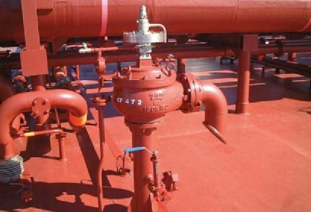
Each section of the cargo pipework that can be isolated by two valves is fitted with an over-pressure liquid relief valve that relieves back to the nearest cargo tank dome. Alternatively, they may be taken to a vent stack via liquid collecting pots with, in some cases, level switch protection and a liquid vaporising source.
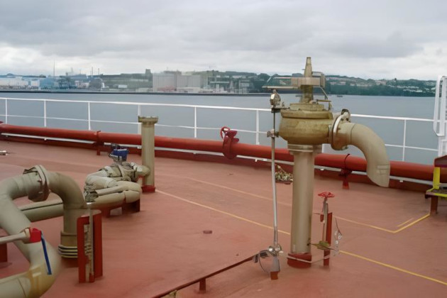
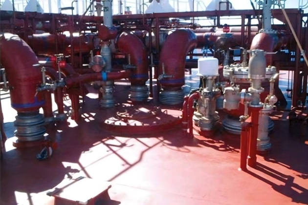
LNG carriers are usually provided with midships liquid and vapour manifold crossovers that are connected to liquid and vapour headers and have connections to each cargo tank. The liquid loading line is taken to the bottom of the cargo tank and the vapour connection is taken from the top of each cargo tank.
No cargo pipework is allowed beneath deck level on LNG carriers, so all pipework connections to tanks beneath the deck level must be taken through tank domes that penetrate the deck.
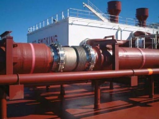
Thermal expansion and contraction must be accommodated in the design of cargo pipework systems. This can be done using expansion bellows, fabricated expansion loops or, where appropriate, by using the natural geometry of the pipework installation. Where expansion bellows are used in a pipework section, it is important not to interfere with pipework supports as they form an integral part of the bellows installation.
Characteristics of a typical cargo line protection device are:
| Set pressure | 10,0 bar |
| Relieving pressure | 13,0 bar |
| No. of sets | Typically 30-40 |
| Flow rate per valve | 7 400 kg/h |
The construction and operation of the relief valves are similar, but the sizes and discharge capacity varies according to the pipeline size. The largest pipeline relief valves have a discharge capacity of 2 956 m3/h and the smallest line has a discharge capacity of 1 398 m3/h.
Each valve has a manual test lever that can be operated to ensure the valve is seated properly.
Pipework expansion bellows and welded joints should be inspected regularly. Prior to loading or unloading, manifold flange joints must be checked under Nitrogen Generator System on Liquefied Natural Gas Carriersnitrogen pressure with a soap solution. Special care must be taken to avoid LNG leaks as the temperature of the liquid can cause steel decks to fracture. For certain operations, such as STS, water may flow on deck as a safety mechanism (water deluge, water bath).
Water, or other contaminants, in the cargo system can be eliminated by taking great care during refit and maintenance operations. Inerting and purging procedures must be strictly followed and cargo manifold strainers are fitted at the unloading port to prevent the possibility of shore contamination. At the load port, the ship is protected against contamination by a strainer fitted in the shore liquid line. This is in addition to the ship supply manifold strainers (60 mesh) that are fitted at each loading.
Other problems that can occur include:
- the valve passing in the closed position;
- a valve not seating properly after it has lifted;
- overenthusiastic shipboard painting that clogs up the springs and workings.
When a relief valve is opened up for maintenance, all parts of the valve should be examined for cracking and pitting. Any spares should be sourced from the original manufacturer. On re-assembly it should be checked that it opens at its set pressure and, on closing, that it seals properly. A security seal should be fitted on completion (usually these are numbered and match records kept).
Cargo Space Protection Devices
Reference: SIGTTO “LNG Shipping Suggested Competency Standards”, Sections:
1 Have an awareness of their purpose and operating principles.
2 Know and understand their principles, operating parameters and limitations:
- design features;
- use of setters to adjust operating pressure.
3 Know and understand the problems that can occur with cargo space relief valves.
Hold spaces are protected by two pressure/vacuum valves of the PORV type per cargo hold. Refer to “Cargo Tank Protection Devices” for further details. The pressure side of the valves operates in the manner as described in “Cargo Tank Protection Devices”.
The vacuum pilot valve opens when the pressure in the space falls and closes when it rises above the negative set pressure. When the vacuum pilot valve opens it creates a negative pressure in the main valve dome. Atmospheric pressure then pushes up the main disc to open the main valve, allowing air to enter the space and re-establish a positive pressure.
When the system pressure rises to the re-seating pressure, the vacuum pilot valve closes and the main dome pressure equalises with the system pressure, causing the main valve disc to re-seat and close the valve.
In the case of Moss spherical cargo tanks, if the chosen means of emergency cargo discharge is pressurisation of the tanks, the relief valves must be provided with a mechanism to re-set in situ.
Cargo Liquid and Vapour Valves
Reference: SIGTTO “LNG Shipping Suggested Competency Standards”, Sections:
1 Have an awareness of their purpose and operating principles.
2 Know and understand their principles, operating parameters and limitations:
- types.
3 Know and understand the problems that can occur with cargo liquid and vapour valves:
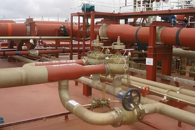
Valves for cryogenic service should have extended bonnets (casing for valve spindle) to prevent freezing of moving parts. Liquid service valves should be able to relieve the pressure caused by entrapped liquid. The manifold ESD valves should be fire-safe and with metallic sealing (i. e. not reliant on soft sealing materials on the valve seat).
The LNG transfer system valves and pumps are normally operated from the CCR. The local valve controls are only used if normal controls fail or if emergency conditions arise.
Under normal operational conditions, valves in use should be fully open. However, loading valves are partially closed when topping-off and pump discharge valves are automatically controlled within the permissible range to prevent overload or cavitation and to control the flow to the shore. The vapour line valves at the tank domes are locked open under normal circumstances.
On completion of any liquid transfer operation, no section of the line should be completely closed. This allows the release of liquid residue and avoids pressure build-up.
Non-throttling valves should be suitable for bi-directional flow. The soft seals of the valves should be suitable for a temperature range between minus 163°C (-163 °C) and +80 °C.
For large diameter valves, special attention should be given to the design of the top flange and tightness testing under transient cooling conditions should be conducted.
| Bore ≥ 150 mm | Stainless steel butterfly valve with extended bonnet and stem. Valve to be ‘top entry’ or “side entry’ type |
| Bore < 150 mm | Stainless steel ball valve, or equivalent, with extended bonnet and stem |
| Liquid throttling | Stainless steel globe valve with extended bonnet and stem |
Al I the valves necessary for the operation of the cargo and ballast system will be operated by separate hydraulic power packs. Under normal operations the power packs and valve operation will be controlled by the IAS. In emergency situations, a manually operated hydraulic pump is available to operate the ballast and cargo hydraulic valves.
| Typical Hydraulic Power Unit Details for Cargo System | |
|---|---|
| Type | 2 sets valve main hydraulic pumps |
| Capacity | 54 litres/min at 140 bar at 1 200 rpm |
| Type | 1 topping up hydraulic pump |
| Capacity | 25,1 litres/min at 140 bar at 1 200 rpm |
| Motors | Main, 18,5 kW, topping up 7,5 kW |
Sampling, vent and drain lines on all liquid and vapour lines that open to atmosphere should be fitted with double isolating valves.
Materials for handwheels, levers and fittings for all valves and actuators should be selected for their resistance to corrosion and compatibility with the valve material.
On older ships, in case of cargo leakage from liquid valves, the valves are fitted with a saveall beneath each that must be filled with water prior to the start of cargo operations. On newer ships, savealls are not fitted.
Cargo Tank Protection System
Reference: SIGTTO “LNG Shipping Suggested Competency Standards”, Sections:
1 Have an awareness of the principles of operation.
2 Know and understand the maintenance requirements:
- maintenance;
- testing.
LNG carriers are required to have a secondary protection for the tank that is capable of containing the cargo for 15 days.
Membrane ship types are fitted with 100 % redundancy in the form of primary and secondary barriers. See Cargo System – Tank Construction“Design and Construction of Cargo Tanks on LNG Vessels” for more information.
Any failure of the primary membrane would be detected by the fixed gas detection system. (See also Section 5.8*).
On the Moss type of ship the sphere works on the “leak before failure” principle, i. e. even if cracks were generated their progress would be extremely slow and likely result in a cold spot on the tank’s outer surface rather than any release of LNG liquid. Any actual leakage would be contained by the outer insulation and splash foil and would run down to the drip tray. (See also Section 5.8*).