Unveiling the intricate world of LNG support systems. This guide dives into nitrogen pressurization, moss systems, and cutting-edge gas detection (fixed & portable) to ensure top-notch safety and flawless IGC Code adherence.
Optimize LNG quality with dew point meters, CO2 monitors, and catalytic combustion for seamless storage and transport.
Nitrogen Pressurisation and Purge
Reference: SIGTTO “LNG Shipping Suggested Competency Standards”, Sections:
1 Have an awareness of the purpose and operating principles.
2 Know and understand their principles, operating parameters and limitations:
- valve arrangements;
- supply pipeline arrangements;
- control and exhaust valve settings;
- monitoring requirements.
3 Know and understand the alarm settings and resulting actions.
Moss system
A flow of N2 is constantly maintained in the annular space between the cargo tank and the insulation.
Supply to the deck is from the E/R buffer tank and this is regulated at 5 bar before it enters the annular space, via an orifice plate and a flow meter.
A differential control system monitors the pressure difference between the hold space and the annular space. The differential is set at 5 mbar.
If the pressure of the N2 in the annular space should rise significantly above that of the hold space, the vent valves operate on the differential pressure between the annular space and hold space and vent to atmosphere. The differential is set on the controller at 5 mbar. The vent valve changes from “auto” to “manual” and remains open. An alarm sounds to alert the operator to the condition.
The annular space is also monitored by the gas detection system and, should gas be detected, it is possible to purge to atmosphere via the vents on deck and change over to the “by-pass supply”; which supplies N2 through a larger orifice.
Membrane systems
N2 is produced by the nitrogen generator in the E/R and stored in a pressurised buffer tank. N2 is supplied to the cargo side pressurisation headers through make-up regulating valves. Depending on the ship arrangements, it may be used for purging gas in the fuel gas line in the E/R.
From the headers, branches lead to the primary (interbarrier) and secondary (insulation) spaces of each tank via supply pressure regulating valves. Excess N2 is vented through exhaust pressure regulating valves. Excess N2 from the primary space is sent to a vent mast. Excess N2 in the secondary insulation space is vented to atmosphere.
The IAS maintains a small but continuous flow of N2 through the insulation space. Therefore, the controller setpoint for the relief regulating valves is usually set slightly lower than the setpoint for the supply regulating valves.
N2 is provided as a dry and inert medium for the following purposes:
- prevention of formation of a flammable mixture in the event of an LNG leak;
- easy detection of an LNG leak through a barrier;
- prevention of corrosion.
To control the insulation space inlet pressure, the IAS provides three PID controllers that are controlled in accordance with the pressure measured at the N2 manifold. The first is for the Response of Insulation Materials to Heatprimary insulation space, the second is for the secondary insulation space and the third is for standby use in the event of one of the master control valves failing. The connection to the primary or secondary space is arranged locally by adjusting manual valves.
| N2 primary and secondary space alarms | ||
|---|---|---|
| Primary insulation space supply pressure differential with atmosphere | High alarm | 10 mbar |
| Low alarm | 0 mbar | |
| Primary insulation space supply pressure | High alarm | 50 mbar |
| Primary insulation space pressure | High-high alarm | 90 mbar |
Primary and secondary insulation space pressures should be maintained at the value recommended by GTT. The setpoint value can be adjusted in accordance with prevailing operating requirements.
| Secondary insulation space supply pressure differential with atmosphere | High alarm | 10 mbar |
| Low alarm | 0 mbar | |
| Primary/Secondary – common insulation space supply pressure differential with atmosphere | High alarm | 10 mbar |
| Low alarm | 0 mbar | |
| Nitrogen purge main line pressure | High alarm | 7 bar |
| Low alarm | 1 bar |
The cargo tank liquid dome void space should be maintained in an inerted condition. The O2 content must not exceed 5 % by volume. O2 and CH4 concentrations must be checked at regular intervals, the interval not exceeding 14 days. This also aids in preventing corrosion.
Cofferdam Heating System
Reference: SIGTTO “LNG Shipping Suggested Competency Standards”, Sections:
1 Have an awareness of the purpose and operating principles:
2 Know and understand their principles, operating parameters and limitations:
- valve arrangements and operation;
- supply pipeline arrangements;
- monitoring requirements;
- temperature control;
- circulating pumps;
- glycol heaters.
3 Know and understand alarm settings and resulting actions.
The cargo containment and handling systems must be completely separated from spaces such as the accommodation and machinery spaces by use of a cofferdam or another means of gastight segregation.
On Cargo Containment Systems of LPG and LNGmembrane ships there is a cofferdam between each cargo tank and between the last cargo tank and the engine room forward bulkhead.
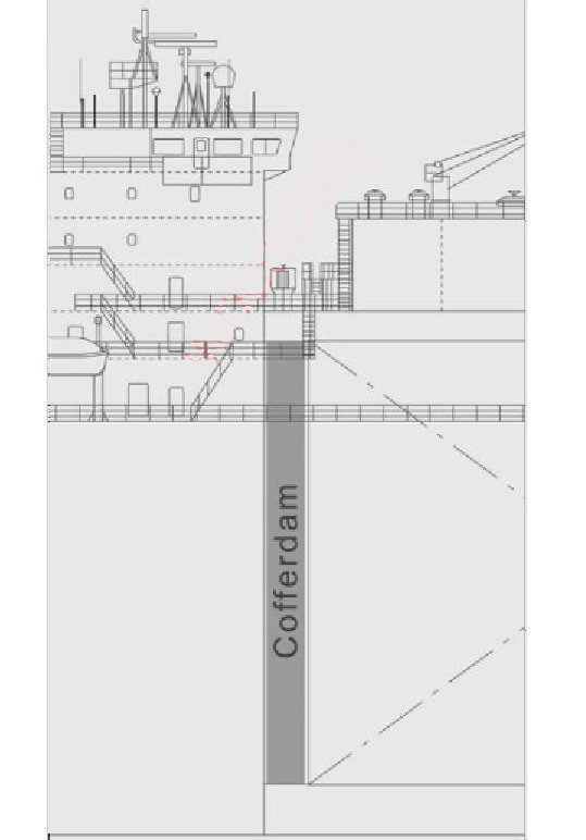
The glycol water heating system for the Cofferdam – Definition and Pronunciationcofferdam is located in the cargo electric motor room. The system heats a glycol/water mix (45 % by volume glycol/water mixture), which is pumped around the cofferdam system to maintain the temperature inside those spaces, when loaded, at approximately +5 °C to protect the steel structure from brittle fracture.
There is a main and standby system. There are also a main and a reserve glycol storage tank. Procedures for topping up the system are contained in the operating manual.
There are usually two heating source options, electric heating or steam.
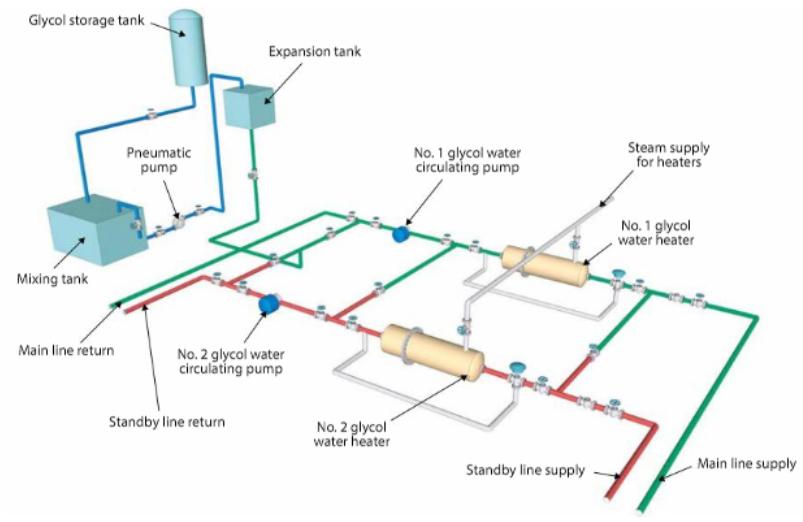
The system on a membrane ship would, typically, comprise of:
- 2 × glycol water centrifugal circulating pumps;
- 2 × steam heaters, with high and low steam demand regulating valves;
- 1 × electric glycol water heater;
- 1 glycol expansion tank;
- 1 glycol storage tank;
- 1 glycol mixing tank;
- 1 pneumatically operated topping up pump for the expansion tank.
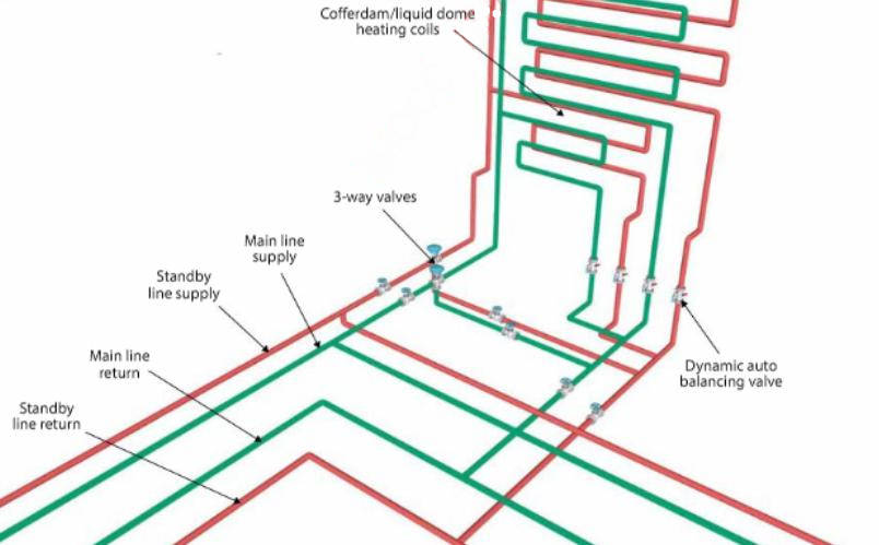
Heating steam flow is controlled by adjustment of the steam flow control valve in accordance with the measured outlet temperature. The inlet temperature to the cofferdam and liquid dome is controlled by adjustment of a 3-way temperature control valve.
Sight glasses in the flow line to each coil allows the glycol fluid flow to be observed. The sight glasses are usually located in the trunk deck passageway.
Any failure of the cofferdam heating system must be treated as serious and repairs must be dealt with immediately. Any accumulation of water or water/glycol mix in the cofferdam areas can be pumped out using the pneumatic pump, which is located in the duct keel. In some cases, an eductor system is also available. Cofferdams should be inspected regularly for cold spots.
Control of the heating coils (typical arrangement, on a 4 tank ship)
Temperature controllers in the IAS manipulate the 3-way type pneumatic control valves in accordance with the measured temperature at the cofferdam and liquid dome. Each controller is responsible for a main and standby temperature control valve.
The system ensures that the cofferdam temperature is at +5 °C, or above, at all times that the cargo tanks are in a cold condition. Each cofferdam can be heated by one of two independent systems, i. e. one in service while the other is on standby duty. In addition, the liquid domes are heated by a separate pair of coils.
Steam heater outlet temperature control. The IAS manages two controllers that maintain the heater outlet temperature at the desired level. One controller manages the heater outlet temperature by adjustment of two steam flow control valves. The other controls the cofferdam and liquid dome inlet temperature by adjustment of a 3-way control valve that directs the heating medium either into the heater or through the heater bypass.
Electric heater control
The electric glycol/water heating system is usually 100 kW in total, split into 50, 30 and two sets of 10 kW elements. Each element is controlled from a local control panel or the IAS, either automatically or manually. In automatic mode the heater elements automatically turn on and off according to the output signal level from the cofferdam and liquid dome temperature controllers. In manual mode the operator is responsible for switching the elements on and off as appropriate.
The maxi mum heating condition is determined by the following extreme operating conditions:
| External air temperature | minus 18 °C (-18 °C) |
| Seawater temperature | 0 °C |
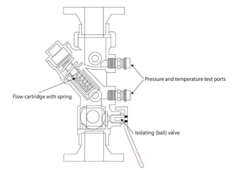
Special valves, incorporating an internal ball valve and flow regulator function, are fitted in each heating coil inlet line for the cofferdams and liquid dome. This is known as a “dynamic auto balancing valve”.
The valve arrangement is set according to the most severe winter conditions and LNG is contained by the primary barrier as normal.
Note: on many of the older class of membrane ships, the liquid dome void spaces are not equipped with heating coils. In addition, cofferdam heating is simply provided using low pressure steam, supplied direct into heating coils.
Fixed Gas Detection
Reference: SIGTTO “LNG Shipping Suggested Competency Standards”, Sections:
1 Have an awareness of the purpose and operating principles:
2 Know and understand their principles, operating parameters and limitations:
- cyclic sampling;
- constant sampling;
- sample points;
- manual measurements;
- automatic measurements.
3 Know and understand their alarm settings and resulting actions.
The IGC Code requires gas detection sampling to complete a cycle every 30 minutes. Continuous sampling is provided for fan protected spaces.
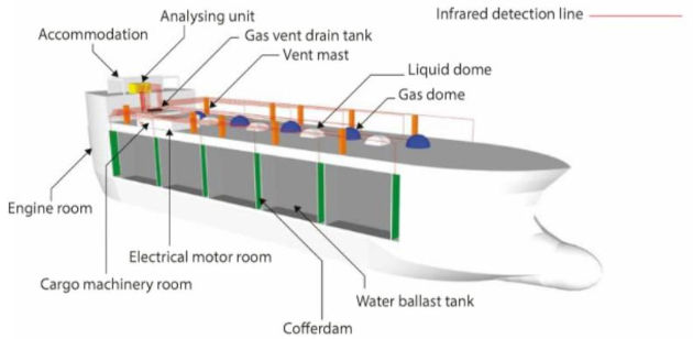
LNG carriers are fitted with fixed gas detection systems that continually monitor the integrity of the cargo containment, cargo handling and ancillary systems, specifically monitoring for any LNG leakage.
IGC Code requirements
The IGC Code (13.6) requires that a fixed gas detection system with audible and visual alarms is installed throughout the ship. Detector heads must be provided in the following areas:
- all enclosed cargo and cargo machinery spaces containing gas piping, gas equipment or gas consumers;
- other enclosed, or semi-enclosed, space, where cargo vapours may accumulate (such as holds paces and interbarrier spaces);
- airlocks;
- spaces in gas fired internal combustion engines;
- ventilation hoods and gas ducts;
- cooling/heating circuits;
- IG generator supply headers;
- motor rooms for cargo handling machinery (compressor room), etc.
The IGC Code (13.6.7) requires that permanently installed gas detection equipment must be of the continuous detection type and capable of immediate response. However, where not used to activate safety shutdown functions, sampling type detection may be acceptable.
Sampling must be at intervals not exceeding 30 minutes (IGC Code 13.6.8).
There are two types of gas detection system used to cover all of the cargo, machinery and accommodation spaces:
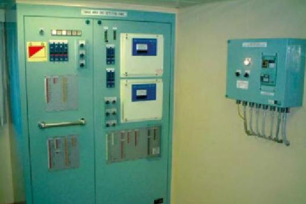
Infrared (IR) gas analyser
This is situated in the electrical equipment room and the sampling sequence is automatically controlled by solenoid selection valves, with the sampled gas drawn into the panel by pumps before being passed over an infrared gas analyser.
The analyser works on the principle that infrared light is absorbed by the methane gas. Methane has a distinctive absorption band in the infrared spectrum. Therefore, if a sample of gas is compared against a reference sample of air, any difference in output from an infrared sensor will be in proportion to the gas concentration.
If the methane concentration of any sample point reaches 30 % LEL, an audible alarm is sounded, an indicator lamp is lit on the panel and a gas detection alarm is activated on the IAS and on the extension alarm panel in the fire control station. At 60 % LEL the gas burning will trip and this will trip any equipment that is running. The entire internal pump system within the analyzer unit is purged with clean air between samples.
The system draws samples and this is known as cyclic sampling. Samples are taken from the following locations:
- interbarriers and insulated spaces or cargo hold spaces – upper and lower;
- cargo tank annular spaces – upper and lower;
- cofferdams;
- duct keel;
- gas vent drain tank for condensate (escape tank);
- gas vent drain tank for bilge;
- bosun’s store;
- vent masts;
- under deck passages – port forward and aft, starboard forward and aft;
- forward pump room;
- cargo machinery rooms, electric motor rooms etc;
- gas sampling cabinet.
There will be ship specific plans for the gas detection sampling points in each of these locations.
As LNG vapour is a gas that is lighter than air, the detector heads should be sited at the highest level in each location to allow for the earliest detection.
Catalytic combustion method
The system consists of groups of 4-20 mA measurement cards, each measuring a single detector and displaying the reading on the front of the card. They monitor the atmosphere by constant sampling at the points where sensing heads are fitted and will detect the presence of any combustible gas should it accumulate. The sensors provide electrical outputs to the cards, proportional to the amount of gas present, and to alarm and indicating panels.
The system is used to monitor flammable gas in the following areas:
- accommodation spaces;
- engine room spaces;
- cargo machinery room spaces.
If the methane concentration of any sample point reaches 30 % LEL, an audible alarm is sounded and an indicator lamp is lit on a separate panel in the CCR and bridge and on the IAS. Provision should be made for regular testing of the installation and “span gas” should be readily available – permanently piped if possible. Sampling and analysis from each detector head is carried out sequentially and sampling intervals should not exceed 30 minutes.
What is a span gas?
A span gas is a gas with accurately known content against which instruments can be calibrated.
In addition to the fixed gas detection system, every ship must have at least two sets of portable gas detection equipment, together with a way of measuring hydrocarbon levels in inert atmospheres (see below).
Read also: Fire Scenarios on liquefied gas carriers
Onboard gas detection equipment is a critical item of safety equipment. However, it is only of value if it is properly maintained and calibrated. Calibration can be carried out on board by ship’s staff using calibration instruments and test gases containing known concentrations of methane in air and methane in nitrogen (known as “span gas”). Calibration is usually done on board but the calibration instruments must be regularly certified.
Any test or span gas used will have an expiry date and must have a valid certificate.
Calibration of the gas detection equipment can also be carried out by service engineers. The safety management system (SMS) and planned maintenance system (PMS) will detail the calibration and test procedures for the equipment.
Portable Gas Detection Equipment
Reference: SIGTTO “LNG Shipping Suggested Competency Standards”, Sections:
1 Have an awareness of the purpose, use and operating principles of:
- oxygen meter;
- combustible gas detector:
- infrared meter;
- catalytic;
- volumetric gas meter;
- dew point meter;
- CO2 meter;
- tubes.
2 Know and understand the purpose, principles, operating parameters, application, calibration and limitations of:
- oxygen meter;
- combustible gas detector:
- infrared meter;
- catalytic;
- volumetric gas meter;
- dew point meter;
- CO2 meter;
- tubes.
Atmospheres in all enclosed and confined spaces must be assessed for traces of hydrocarbon gases (as appropriate) and by using oxygen detection equipment, to ensure 20,9 % O2 prior to entry by personnel.
IGC Code requirements
The IGC Code (13.6.19) requires that every ship is provided with at least two sets of portable gas detection equipment. Additionally, a suitable instrument for the measurement of oxygen levels in inert atmospheres must be provided (13.6.20).
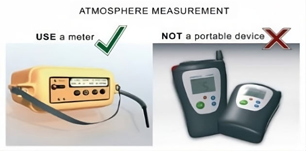
Measurement of an atmosphere must be carried out using an approved, certified and calibrated portable gas detector.
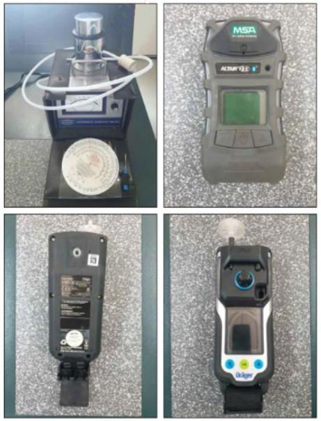
It is common practice to have a multifunctional device rather than having a variety of analysing devices covering individual gases. A typical multifunctional device will cover O2, CH2, CO and CO2, with measurement ranges and measuring principles as follows:
- combustible gas (CH2), 0-100 % LEL, 5-100 % volume. Non dispersive infrared sensor;
- oxygen (O2), 0-25 %. Galvanic cell (a catalytic sensor);
- carbon monoxide (CO), 0-1 000 ppm. Electromechanical (catalytic sensor);
- carbon dioxide (CO2), 0-20 % volume. Non-dispersive infrared sensor.
All equipment must be rated as “EX” (“explosive proof”) and for use in hazardous areas.
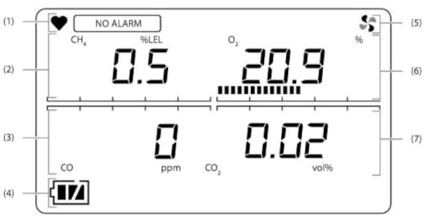
1 – operating display status; 2 – combustible gas concentration display, digital and bar graph; 3 – carbon monoxide concentration display, digital and bar graph; 4 – battery level icon; 5 – pump driving indicator; 6 – oxygen concentration display, digital and bar graph; 7 – carbon dioxide concentration display, digital and bar graph
In the event of an alarm, a buzzer will sound and the alarm LED will blink.
All devices must be calibrated before use and zeroing and span adjustment of sensors using calibration gases should be performed at periods as required by manufacturers’ recommendations and company specific requirements.
Major repairs may require devices to be sent ashore.
Be aware that drawing liquid into a gas measuring instrument will result in error or malfunction.
Combustible gas indicators (explosimeters) cannot be used for measurement in inerted atmospheres. You must use an instrument designed for operation in inerted atmospheres.
Dew point meter
Typically, a fixed Complete Manual for Engineers about Dew Point Reservoirsdew point meter is fitted for continuous measurement of the moisture content during inerting, aerating and drying of the cargo tanks and systems. A minimum of one portable dew point meter should be available, although it is good practice to have two calibrated serviceable dew point meters on board.
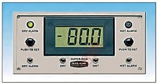
When running the IG system, the dew point meter located inboard of the dryer units will power up automatically when the IG system is started. Alarm or control settings are set by the user. The typical range is from +20 °C to minus 100 °C (-100 °C) dewpoint, which is 23 000 ppm down to nearly 1 ppb.
Alarm or control settings should be easily set by the user to provide instant alarms. Calibration must be accurate for different gases and the flow rate should have no effect on the accuracy of the instrument.
CO2 meter
Where IG is used in areas that will come in to contact with the cryogenic temperatures of LNG (minus 161,5 °C (-161,5 °C)), the CO2 content of the IG will have to be monitored as shipboard generated IG contains around 15 % CO2. This will freeze at minus 56,6 °C (-56,6 °C) and produce a white powder that can block valves, filters and nozzles.
Tubes
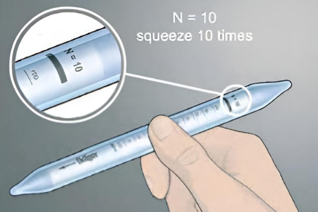
Toxicity meters commonly operate on the principle of absorption of toxic gas in a chemical tube, which causes a colour change. The gas is aspirated through the tube, by means of bellows, until a colour change is achieved. Both ends of the sealed glass tube must be broken immediately prior to use and inserted correctly, as indicated by an arrow. The number of aspirations required will be indicated on the tube and data information sheet.
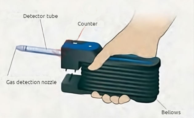
Most often, on LNGCs, this meter is used to measure for toxic gas such as benzene (C6H6), but it can also be used for measurement of other toxic gases, depending on the tubes available.
Tubes have an expiration date and should be recycled if expired.
Oxygen meter
This is used to give an accurate reading of the O2 content within the space or compartment tested. The required level for entry to enclosed spaces is 20,9 % (i. e. fresh air).
There are different types of oxygen meter, from the older types that operate by diffusing O2 to the more sophisticated detection instruments that incorporate dual or triple scales, each of which can be used for different purposes. Oxygen analysing instruments offer range scales that are extremely sensitive. They use batteries that may be rechargeable.
Oxygen metering instruments should always be calibrated with fresh air (20,9 % O2) and N2 (0 % O2).
Combustible gas detector
A combustible gas detector measures:
- % Gas setting – the percentage gas reading by volume in a compartment or tank. This will measure from 0-100 % gas.
Methane has a flammable range of between approx. 5,3-15 % gas by volume and combustion would be sustained if the O2 level was above 13 %. This is why the O2 content is maintained at levels safely below that value.
- % LFL – this measures the percentage of gas up to the level of the lower flammable limit (LFL).
A combustible gas detector should be calibrated, using span gas, at prescribed intervals.
A span gas is a gas with accurately known content against which instruments can be calibrated.