The LNG Transfer Arms and Manifold Draining, Purging, and Disconnection Procedure is a critical protocol designed to ensure the safe and efficient handling of liquefied natural gas (LNG) during transfer operations. This document outlines the principal objectives of the procedure, emphasizing the importance of safety, environmental protection, and operational efficiency.
By adhering to the guidelines presented in this procedure, personnel can minimize risks associated with LNG transfer and maintain compliance with industry standards. The annexes provide additional examples and detailed steps to facilitate understanding and implementation of the procedure.
Introduction
This advice has been prepared following reports, from a number of members, that there appears to be confusion and misunderstanding among some ship and jetty operators over the safe conduct of this operation.
This advice specifically pertains to terminals employing rigid transfer arms. (The basic principles are applicable for hose systems that may be used for LNG ship-to-ship transfer, but there will be differences in the detail.
Principal Objective
The principal objective is to disconnect the hard arms in a manner that eliminates any risk of liquid release and reduces the release of cargo vapour to the atmosphere to an absolute minimum. For this operation to be conducted safely and in a timely manner, it is essential that there is a carefully thought out procedure in place and that there is good communication between the ship’s staff and the shore operational staff, both of whom bear responsibility for safe conduct of the operation.
The process has a number of logical steps:
- Lining up the drain system from the manifolds to a tank.
- Isolation of liquid and vapour valves on either side of the manifold connection.
- Removal of liquid from the manifold connection and transfer arm.
- Purging of flammable vapours from the connection.
- Verification that the target conditions (flammable gas concentration) have been achieved.
- Disconnection of the manifold.
Drain System
On most LNG ships the manifold drains are routed via the spray header to a Best Practices for Gas Tank Installation and Cargo Tank Insulationcargo tank. Check that the spray valves are open on one tank and that all relevant line valves leading to the tank are open. At this stage, all drain valves at the manifold should be closed.
Isolation of Liquid and Vapour Valves Either Side of the Manifold Connection
For the shore side, this means closing the valve at the base of the transfer arm. For the ship, this means closing the first valve inboard from the manifold flange, which in most cases is the ESD valve. The majority of LNG ships now have double shut-off valves at each liquid manifold and both of these should be closed. The valve to the manifold drain system described in 1 above should then be opened.
Removal of Liquid
This is usually carried out in a series of stages using nitrogen from ashore. The nitrogen pressure is used to push the liquid from the shore side of the apex of the transfer arm back to shore and, from the ship side, into the LNG Cargo Handling Systems and Their Operationsship’s drain system and back to a cargo tank. Completion is usually indicated by a sudden fall of pressure in the transfer arm/manifold and a change in sound as the flow in the drain system goes from liquid to gas. Drains and vents to the atmosphere should not be opened at this stage in the procedure.
Note: It has been reported that some have suggested cracking open a drain to the manifold to check that liquid has been removed. This is potentially dangerous, unnecessary and should not be done at this stage.
Draining the section between the double shut-off valves (if fitted) and the manifold valves on the ship’s manifold may also be accomplished using normal heat in-leak (vaporisation) to pressurise the space and force the liquid into the drain system.
Purging Flammable Vapours
The most common procedure is to pressurise the section, with nitrogen, up to 4 or 5 bar with all valves closed, and then open the drain valves to the line into the ship and then back to the cargo tank. This process may need to be repeated two or three times.
Verification
This is a key aspect of ensuring the safety of the disconnection procedure. The vent in way of the manifold is opened and the vapour is tested using a meter calibrated for measuring methane in nitrogen. A typical target level is 2 % by volume in nitrogen to ensure a margin of safety when disconnection occurs and the vapour and nitrogen mixture is achieved. As a final check, briefly crack open the drain to the drip tray to ensure that no liquid is lying in the bottom of the line.
If both tests indicate safe conditions, fully depressurise the manifold connection by closing the drain line connections to the cargo tank (to prevent back flow), opening the drains to the drip tray and the vents for disconnection. It has been noted that leaving a pressure of about 0,5 bar in the space reduces or prevents an increase in hydrocarbons in the space. If this is adopted all lines should be depressurised before disconnection is commenced.
Disconnection of Manifolds
Once the verification process is complete and the arm fully depressurised, the drain valve should be left open in case of any small leakage past valve seats. A final check should be made to ensure that the methane content remains below 2 % by volume before disconnection.
Disconnection should not commence until all arms have been satysfactorily purged in case(as has happened in the past) the wrong arm is inadvertenly selected and disconnected.
The manifold blanks should be installed immediately and the drain and vent valves then closed.
Overview
The staff in the manifold region should be limited to essential staff only. All staff engaged in or working in the vicinity of the operations described in this paper must wear appropriate personal protective equipment (PPE). Gas detectors must be in good order and correctly calibrated. Any tools used, e. g. spanners, must be the right size for the job, clean and in good condition.
Note: Occasionally one still sees references to «non-sparking» hand tools (e. g. spanners). These were typically made of non-ferrous metal alloys. ISGOTT discusses this in section 4.5.2 of the latest edition (5th edition published 2006) and does not recommend their use. SIGTTO supports this position.
Annex 1 briefly describes two incidents where the correct procedures were not followed.
Annex 2 provides an example of a detailed procedure prepared by a SIGTTO member. This is purely for illustrative purposes to show the level of detail that may be needed. Please note that not all manifolds and drain systems are configured the same. We therefore strongly recommend that you develop procedures that are right for your ships/terminal, rather than copy someone else’s, since they may not be appropriate.
It is an important principle that the procedure is clear and agreed by both ship and shore. We note that this particular member has, on their written procedure, included space for inserting agreed changes and signature by both parties specifically for this operation.
Verification using a gas detector is essential. While time or number of cycles of pressurisation/depressurisation may be a useful indicator, the principle of testing with a detector must be adhered to. If reliance is placed only on a time or cycle based system, a leaking valve in the cargo system, on ship or shore, may go undetected, leading to disconnection taking place in unsafe conditions.
Another issue with some gas detectors is that they automatically switch from % volume to % LFL at low concentrations. Be sure you know what your meter is reading when you use it!
The operation may be conducted sequentially, i. e. all steps completed for one arm before moving to the next, or in parallel. The key factor in selecting which method usually rests on the ability of the shore system to maintain the necessary supply of nitrogen.
It is normal to leave the vapour arm to last. The procedure is similar except that there is no liquid to remove.
Conclusions
Mishandling or poor execution of the drain and purge procedure can lead to serious incidents. SIGTTO recommends that:
- All members review their procedures for draining and purging manifold connections for adequacy. If a detailed written procedure is not available, one should be prepared following the principles described above, recognising that not all terminals and ships have identical arrangements.
- The procedures are specifically discussed and agreed by both ship and shore prior to the operation.
Annex 1
Incident 1
This incident occurred while draining and purging the manifolds at the end of loading. The weather conditions were dry and very still (nil wind). The purging was proceeding with the vents and manifold drains to atmosphere open. Progress of the operation was slower than normal as a result of problems with the nitrogen supply. (There may also have been some pressure to complete the operation to avoid delay to sailing.) A member of the ship’s staff approached the vent to check with a gas detector when the gas cloud ignited. The fire was very short lasting, really only a flash fire, and had largely burnt out before the fixed shore monitor was brought into operation. However, the crew member involved suffered serious burns.
Despite thorough investigations, the source of ignition has never been definitively identified. It may have been some unexplained fault with the gas detector or it may have been static electricity. Another possibility was a spark generated by a dropped object. No evidence could be discovered to support any of these hypotheses.
Incident 2
The Secretariat has recently become aware of another incident. During the draining and purging operation after cargo discharge a release of LNG and vapour occurred. The LNG came into contact with two persons and several persons were located inside the vapour release. Fortunately, no one was hurt and there was no ignition of the vapour.
The immediate causes for the release were identified as:
- Failure to drain the piping between the ship’s ESD valve and the double shut valve.
- Failure to close the hard arm vent valve when the methane content was greater than the agreed percentage by volume.
- Opening an ESD valve with hard arm vent open.
Root causes for the release were identified as:
- Failure to comply with established procedures.
- Failure to have adequate procedures.
- Competence of personnel undertaking the operation.
Annex 2 Example Procedure
Cargo Arms and Manifolds Draining and Purging Procedure
This procedure is the standard procedure for draining and purging and should be followed by all vessels as far as possible. It should be compared with the terminal procedure during the pre transfer meeting. Any divergence has to be agreed between the ship and the shore and the revised procedure signed by both parties should be issued for use upon the completion of bulk General Arrangement of LNG Custody Transfer Systemcargo transfer. The procedure applies to liquid and vapor arms.
Purpose of Draining and Purging
To disconnect cargo arms from ship manifolds under safe conditions, always ensuring that, at no time, a flammable condition can be attained.
To achieve this all piping space between ESD valve, ESD by-pass valve and liquid arm isolating valve, prior to disconnection, must be measured by a suitable gas meter at less than 2 % gas content in a nitrogen background.
Source of Nitrogen Injection
Shore side.
Alternative Source
Ship’s side through manifold vent valve.
Ship’s Side Reception of Drained Cargo and Purged Gas
No. 4 cargo tank as described below.
Nitrogen Pressure for Effective Draining/Purging
2 ~ 5 bar. Upon reaching 5 bar, pressure should be released or nitrogen supply should be stopped. Piping should remain always pressurized at a minimum positive pressure of 0,5 bar until disconnection of hard arms.
Sequence
One pair of manifold/liquid arm each time.
Pressure Monitoring
Manifold pressure gauge.
Initial Line Up
Cool down (spray) valves from port or std side manifolds to no. 4 ct through liquid header:
Port Side:
CS 025 & CS 035 to CL 407 & CL 400.
Starboard Side:
CS 024 & CS 034 to CL 407 & CL 400.
These valves will remain open up to completion of operation.
Attending Ship Personnel
Cargo engineer, deck officer, one able seaman.
Attending Shore Personnel
Assigned shore representative(s) as agreed during pre-transfer meeting.
All should wear proper PPE and carrying portable Intrinsically Safe UHF radios for effective communications between CCRs and jetty personnel.
Duties
Cargo engineer and shore representative are responsible for carrying out the operation.
Deck officer is responsible for the safety of the operation. He also monitors the pressure and measures the gas content. AB assists as directed.
Standby Equipment
Gas meters, ship’s nitrogen hose, necessary tools for the job.
Before Draining and Purging
All persons involved, ship and shore, should have a clear understanding of method to be followed. To achieve this a meeting should be carried out before the job, the requirements of the agreed procedure fully followed and satisfied and relevant entry to be inserted in cargo operation book.
Upon Completion of Draining/Purging and Before Start of Hard Arms Disconnection
Relevant VSL-PTW-003 form to be completed and signed. LO/TO to be carried out in remote valve ESD (set to passive mode).
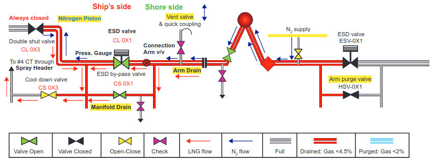
Draining of Ship-Shore Piping Complex
Any gas flowing under pressure into liquid filled piping is always ascending in inclined and vertical pipes until reaching a dead end, (double shut valve, top of cargo arm) where it creates a «gas piston», pushing the liquid downwards. In horizontal pipes of large and medium diameter the gas always lays on top forcing the liquid downwards. A gas piston is also created with LNG trapped between closed valves as it warms up. (Gas means either nitrogen or cargo vapor). Under a certain gas pressure the liquid escapes from any opening at the lower part of piping. Pressure of 1 bar is enough to push LNG through a narrow pipe up to 22 m higher of the lower point that this pressure is exerted.
Read also: Emergency Shutdown System (ESDS) on Liquefied Gas Carriers
Pressure should not allowed to drop below 0,5 bar or nitrogen should not stopped flowing throughout the entire operation.
This Procedure has been Agreed between Ship and Terminal representatives with the changes described in the last page.
- Vessel: _______________.
- Representative: _______.
- Signature: ____________.
- Terminal: _____________.
- Representative: _______.
- Signature: ____________.
- Date: _____. Time:_____.

1 Upon completion of cargo operation.
- Verify that trunk deck cargo liquid lines are drained as per cargo manual. Verify that double shut valves are 100 % closed.
- Line up spray line from connected manifolds to No. 4 cargo tank as described above.
- The ESD valve and ESD bypass valve will remain Closed while the shore side part of arm is blown back ashore by nitrogen (terminal staff will drain and purge the shore side arm into their piping or a vessel such as a knock-out drum, as shown above).
- Cool down valve should be Open to relieve pressure between the double shut valve and the ESD valve into # 4 CT. (The trapped & under pressure cargo will drain into # 4 CT. This practice will speed up the ship side piping draining).
2 When the terminal has confirmed the shore side section of the hard arm is liquid free the ships staff will Open the ESD bypass valve.
3 After terminal staff confirm that they have finished with draining the shore side arm, proceed to 2nd Stage.
- Verify that Jetty has closed the arm purge valve. Verify that Shore N2 supply valve is open.
- Open ESD valve (ESD valve may remain closed during this process on the terminal’s request. This will increase the number of cycles required to achieve the 2nd stage draining objective). Confirm arm’s valve is open. Monitor the pressure. Listen to the cargo flowing. When pressure suddenly drops and liquid flow stops, close the cool down valve.
- Allow pressure to rise up to 5 bar and Open the cool down valve until pressure drops to 0,5 bar. Close cool down valve.
- Repeat step 3 one more time. N2 pressure can be lower but not less than 2 bar. (Empty lines need much more nitrogen)
- Open Vent valve slowly. Check methane % by volume through vent valve and if it is less than 4,5 %, crack open manifold drain valve to verify that piping is dry. A few droplets may initially be observed. If you observe free liquid flow close the drain valve and repeat steps 4 and 5. If the piping is dry, check the gas content at the arm’s drain valve.
- Upon verifying that piping is liquid free and that the methane % by volume is less than 4,5 % at the drain valve, close the drain valve. Verify that the arm drain valve is closed. Proceed to Stage 3.
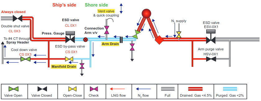
- Close the ESD valve. Close the ESD bypass valve. Let pressure to rise up to 5 bar.
- Open ESD by-pass valve until pressure drops to 0,5 bar. Close the ESD bypass valve.
- Open Vent valve slowly. Check the methane % by volume through vent valve. If reading is less than 2 % methane % by volume Open Manifold Drain valve and measure Methane % by volume to read less than 2 % Methane % by volume. Shore side may check Methane % by volume through arm drain valve. If any reading is above 2 %, Repeat steps 1 to 3 until all check points are less than 2 % Methane % by volume.
- Close ALL valves including arm’s valve (PERC), with the piping pressurized at 0,5 bar (Piping (blue section) should remain pressurized until Arm disconnection to prevent leaks and ensure valves tightness). Set ESD valve to «passive». Proceed with draining and purging of remaining liquid manifold/arms following above 3 Stages.
Disconnecting a Cargo Arm:
- Check pressure to be equal or above 0,5 bar.
- Check methane % by volume at manifold drain valve to be less than 2 %.
- Depressurize through check points.
- Disconnect hard arm (by terminal’s staff).
- Fit blind flange & tight the bolts.
Changes Agreed Between the Ship’s and the Terminal’s Representatives.
Any agreed changes should not affect the recommended safety standards of this procedure as described in 1st page.
Pressures should not exceed 5 bar. Arms should not disconnect at higher than 2 % methane percentage by volume.
Valves mentioned as closed prior disconnection should remain closed.
| No. | Description |
|---|---|