Explore the critical aspects of valves selection and testing for LNG applications in this detailed article.
- Scope
- Introduction
- Selection of Valves for Cryogenic Systems
- Specific consideration for ESD Valves
- Construction Materials for Cryogenic Valves
- The Effect of Material Mass in Valve Design
- Design Considerations for Valves in LNG Service
- Valve Testing
- Guidance to Inspectors when Testing Cryogenic Valves
- Checking for Liquid Lock in the Stem of the Cryogenic Globe Valve
- Current Codes and Standards Referencing Valves for LNG Service
Learn about cryogenic system requirements, ESD valve considerations, suitable construction materials, design challenges, and testing guidelines to ensure reliability and safety in LNG operations.
Scope
This article is intended to offer guidance to designers and operators on the general requirements for valves for liquefied natural gas (LNG) service. It is also considered to be applicable to valves for liquefied ethylene and liquefied ethane service. the valves in these services are generally designed with an operating temperature range of +80 °C to minus 196 °C. Some aspects may be applicable to valves in refrigerated liquefied petroleum gas (LPG) service. this guidance is primarily intended for the shipping and storage of these products but may be applied throughout the LNG and LPG industries as appropriate. nothing in this document seeks to override the applicable standards and codes that may be applicable to these valves.
Where the term “LNG” is used in this article, it may be read as also being applicable to liquefied ethane and liquefied ethylene service.
Introduction
Specific design requirements apply to ensure that a valve will work effectively in a cryogenic The term “cryogenic” refers to the branches of physics and engineering that study very low temperatures. as a strict definition of upper temperature limit for cryogenic systems is not presently universally agreed, for the purposes of this document, “cryogenic” is assumed to refer to service temperatures below minus 80 °C.x system. For example, the valve design must take into consideration thermal expansion and contraction and still provide a tight shut-off without leakage across the seat. an aim in the casting design is for the material mass to be minimal to improve cool-down times, while still meeting the relevant design codes and standards. The potential problem of “liquid lock” in the valve body must also be addressed.
This document aims to introduce the fundamentals of cryogenic valve design and testing in general and to consider the minimum technical requirements in more detail. The standards offered as examples are european committee for Standardisation, (CEN), standards. However, the appropriate national codes or standards and class requirements should be referred to where applicable, or where they are more stringent. The major codes and standards on this subject are referenced in the bibliography.
Valves used for LNG service should always be designed to meet the relevant applicable cryogenic standard. BS 6364:1984 is an example of such a national standard, that applies to all cryogenic valves. Similarly, BS EN 12567:2000 is an example of a current national standard for LNG isolation valves that covers the suitability and appropriate verification tests for LNG service. Another example of a national standard to consider is BS EN 1626:1999 cryogenic vessels – Valves for cryogenic service; this standard covers materials, design and manufacture.
Selection of Valves for Cryogenic Systems
The basic engineering design criteria that apply to the decisions on where to place valves and their function in Cryogenic Systems include the need for isolation, Gas Control Station Workflow Management Guideflow control (throttling) and sampling. The major differences between valves used for low temperature duty, compared with those in ambient temperature systems, arise from the nature of cryogenic fluids themselves and the special hazards of handling them.
For example, in the late 1950s a major fire was caused on an LPG plant when a single drain valve was left in what the operators thought was the closed condition. In fact the valve had been shut on a plug of frozen hydrocarbon hydrate or ice, and when the ice/hydrate melted there was a major leakage of liquid product that led to a serious incident and several fatalities. Since then, Codes of Practice have recommended that, in situations where this type of incident could occur, two valves are fitted in series and provided with a plugged outlet.
“Liquid lock” in the valve body is a feature where, by the action of closing the valve, some liquid becomes trapped in a cavity within the valve body. This is potentially dangerous because liquefied refrigerated gases, thus trapped, may exert sufficient pressure on expansion to cause plastic deformation of components, or ultimately rupture. This phenomenon is most significant in LNG systems, although valves in refrigerated LPG service may also be at risk. In practical valve design, any liquid trapped in the body cavity of a valve must have a relief path to prevent over-pressurisation.
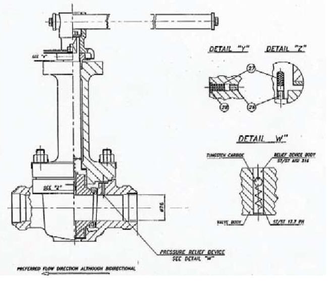
Valves with internal relief to overcome this “liquid lock” phenomenon are usually marked on the body with an “upstream” and “downstream” label, or an arrow cast into the body. It is essential to make sure the valves are fitted the right way round. However, manifold valves (which are bi-directional) should, if they are marked with a single arrow, have that arrow pointing outboard, or have the downstream side outboard. However, the presence of such indication does not, of itself, guarantee a satisfactory valve design.
When ordering replacement seats for cryogenic valves it is important to specify the duty intended (e. g. operating temperature range or list of cargoes to be handled) because makers may use different materials for LPG, ethylene and LNG duty in valves that are externally identical.
One other important consideration during the design stage is the decision whether to fit flanged or welded valves. Experience shows that cryogenic systems may have some transient leakage from flanges when cooling down, especially large diameter systems, and in many cases designers seek to minimise this potential leak risk by fitting ‘all welded’ valves. An important practical consideration here is whether future maintenance, such as seat replacement, can be carried out with the valve in position. It is also important to consider if the total line length between flanges still allows for future repair and maintenance.
Other design considerations that are of specific relevance to cryogenic systems are the possibility of “plugging” due to ice or hydrate formation (in practical terms, usually only encountered with LPG) and brittle fracture of materials unsuitable for cryogenic applications. The incident outlined, where LPG flowed out of a drain system when the hydrate melted, is one example of such an occurrence. Similar concerns may arise from the inadvertent opening of a drain valve as that could cause cryogenic liquid to spray unexpectedly onto a steel structure and result in “brittle fracture”.
As an example, a quarter-turn ball valve used for sampling on a cargo pump discharge line on an LNG carrier would usually have a plugged or blank-flanged outlet. However, if the blank was left off, for example, after atmosphere testing during “gassing up”, and the ball valve was knocked accidentally during a subsequent cargo discharge as someone passed by, maybe during night hours, the stream of LNG could cause the deck steel to fracture before it could be stopped. It is to be expected that a cloud of flammable vapour would also be formed. This is why duplicated needle-type valves (as the multiturn operation helps to avoid this scenario) are to be preferred, particularly for sampling valves, and with sufficient distance between them to minimise the hydrate blockage risk. Systems used for vapour only pose less risk and so may have single sample valves with blanked or plugged outlets.
Read also: Gas Tanker Equipment and Instrumentation
One feature of cryogenic valves is the extended bonnet & shaft design. There is no hard and fast temperature threshold for when such arrangement is used, but most designers adopt this layout for cargoes below minus 55 °C. Therefore, valves with extended spindles and bonnets are normally used in ethane, ethylene and LNG service, and are less usual for refrigerated LPG applications. The purpose of the design is two-fold. The extended spindle provides a temperature gradient to minimise the risk of frostbite to the operator; the spindles are usually made from stainless steel, which is a relatively effective heat insulation material. Secondly a small amount of cargo liquid is permitted by design to enter the lower part of the bonnet. This small amount of product evaporates inside the extended spindle. This has the benefit that the sealing arrangements should seal vapour at or near ambient temperature conditions. This gives better and more reliable sealing performance than for cryogenic liquids, and should eliminate the risk of freezing in way of the seal. It is important that the valve stem seals are maintained in good order. If not, water may enter and lead to valve failure through freezing of the internals. It is to be expected that the valves most likely to suffer this problem are those in intermittent service.
It is apparent that extended spindles can only work correctly if fitted in or near the vertical up position. It is also important that the bonnet is positively fixed to the body so that it is impossible to unscrew it accidentally when the valve is opened, as could happen if the bonnet was simply threaded into the valve body.
Ball and butterfly valves which are required to perform an LNG System Features and ControlsEmergency Shut Down (ESD) function should be of a “fire-safe” design to an applicable standard, such as BS 6755 Part 2, or equivalent. (The reason for fire testing the metal seated ball and butterfly valve is that the seat is usually of a thin section that may distort during a fire, leading to leakage.)
Specific consideration for ESD Valves
The normal design conditions set out in the IGC Code should apply, especially in terms of local & remote actuation, avoidance of pressure surge and positive closure of the product flow.
The design of ESD valves should be such that the actuator is positively connected to the valve plug such that the valve cannot remain open when the actuator is in the closed position, or indicating closed.
Construction Materials for Cryogenic Valves
Valve materials should be austenitic stainless steel or alternative materials as may be specified in applicable standards such as BS EN 12567:2000 Isolating Valves for LNG – suitability and verification tests (4.10) or BS EN 1160 : 1997 Installations and equipment for LNG. General characteristics of liquefied natural gas.
For marine applications austenitic stainless steel type 316 should be used for all external components, any other materials used should be suitable for marine application and not set up an electrolytic couple in excess of 250 mV, (see BS EN 12567:2000 section 4.11).
The Effect of Material Mass in Valve Design
Boil-off will occur in an LNG system when a valve at ambient temperature is opened to allow liquid flow. As the liquid flows along the pipeline, heat will be transferred from the stainless steel pipe and valve components to the LNG. This will boil off a quantity of liquid until the pipeline and valves reach the same temperature as the LNG. Therefore, when selecting a cryogenic valve, it is important that the material mass is considered. The more material the valve contains, the longer the cool down period will be and the more will be the boil-off gas volume produced.
It is possible to calculate heat loss and boil off gas production during cool down. For example:
| Specific heat of stainless steel | 490 J/kgK |
| Latent heat of LNG | 509 kJ/kg |
| Temperature change of stainless steel (from 0 °C to minus 160 °C) | 160 °C |
| Heat lost by stainless steel | 490×160 = 78 400 J/kg = 78,4 kJ/kg |
| Amount of LNG boil off | 78,4 kJ/509 kJ/kg = 0,154 kg |
| Density of gas | 0,678 kg/m3 |
| Gas produced | 0,227 m3 = 227 litres per kilogram of stainless steel |
The above calculation can be adapted to meet specific temperature requirements.
Design Considerations for Valves in LNG Service
When selecting a valve it is important to ensure that it is designed and manufactured to the relevant standard or code; this may require compliance with more than one standard or code.
For general design features specific to cryogenic requirements see table below.
| Element | Design features |
|---|---|
| Stem sealing device. (Gland packing at the top of the extension) | Consider the wear characteristics of the packing material and the surface smoothness of the valve stem. Consider the potential vapour leakage from the stem in terms of ISO 14000 requirements. |
| Bonnet Joints Attaching the valve cover to valve body | To meet BS EN 12567:2000 (4.3). The valve shall be designed to take into account the thermal stresses in transient state occurring during cool down and warm up operation. |
| Actuating thread | Consider potential seizure due to materials used. Anti-galling austenitic stainless steel prevents seizure and valve failure. |
| Anti-blowout stem/shaft/spindle retention. This applies to all valves with stem/shaft/spindle protruding into the pressure area | To meet BS EN 12567:2000 (5.11). Each valve stem/shaft/spindle shall be fitted with an anti-blow out feature for maximum safety. Serious injury can occur if the stem could be ejected with force when the valve is opened. |
| LNG liquid lock in the stem/shaft/spindle area when the valve is in the full open position | To meet BS EN 12567:2000 (4.4). To ensure liquid is not trapped in bonnet extension or any other cavity of the valve arrangement. a safety device must be fitted to any area where liquid lock can occur to prevent over pressurisation. The device must not release cargo to atmosphere. |
| Obturator/disc/wplug. The mechanism to seal the valve | The design must take vibration into account, especially for marine applications. A vibration-proof connection between stem and plug should allow sealing faces to remain stationary during final closing to prevent galling, wear and seat damage. |
| Flow Path | The bore should be selected taking account of pressure drop across the valve. |
| Cryogenic Valve Automation | The valve must be installed so it is able to support the weight of the actuator in all conditions including marine applications (where vibration is significant). This is to prevent failure due to excessive stresses from the weight of the actuator. It may be necessary to fit local supports and to strengthen the pipeline in way of the valve, especially in branch locations. |
Valve Testing
For gas ships, the IGC Code specifically requires tightness testing for cargo valves that are to be used for service temperatures below minus 55 °C. For systems working at temperatures above that limit, normal Class requirements should apply in respect of cargo valves.
The following general tests are expected to be carried out on all valves, but this document will concentrate on the tests specifically required for cryogenic valves (1.4 and 1.5):
| Shell strength test | Hydrostatic or pneumatic test to 1,5 × Maximum working pressure. |
|---|---|
| Shell leak test | Pneumatic test to 1,1 × Maximum working pressure. |
| Seat leak test | Pneumatic test to 1,1 × Maximum working pressure. |
| Cryogenic prototype test | To BS 6364: 1984 Appendix A. |
| Cryogenic production test | BS 6364:1984 provides procedures for cryogenic testing of valves. This document offers guidance and direction on what to look for to ensure that the test is carried out correctly. |
A summary of the procedure is given below:
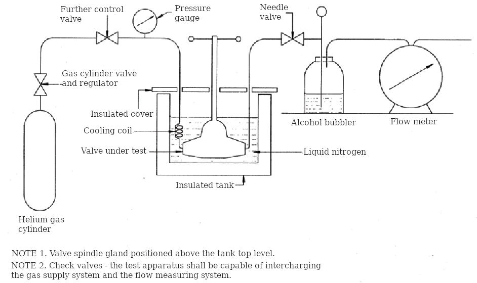
- The valve to be tested is submerged in liquid N2 and allowed to cool down. When equilibrium has been reached the liquid N2 will stop boiling.
- The valve should then be closed and helium introduced as shown in diagram 1. It is normal for small bubbles to rise from all over the valve due to very small quantities of heat passing from the valve to the liquid and these need not cause concern. Bubbles from the joints, stem packing or outlet are signs of leakage.
- For what is considered to be a very accurate leakage test that does not rely on bubbles rising from the valve see EN 1626 (external leakage method).
- These tests are very stringent because, in accordance with Graham’s law of Diffusion, Helium can show up leakages that will not happen with fluids with higher molecular weights.
- The use of liquid N2 at minus 196 °C for testing also gives an extra margin compared with testing on the actual cargo liquid. The use of liquid N2 instead of LNG also avoids flammability hazards on the test rig.
Guidance to Inspectors when Testing Cryogenic Valves
It is recommended that third party inspection is utilised during cryogenic valve testing for Class approval.
The use of a third party inspector can assist in ensuring that the valve test system is strictly in accordance with the relevant test procedure and that there are no leakages (pin holes in pipe work) extra pipe work, bypass systems, heaters or other mechanisms that would affect the accuracy of the readings and results recorded. It is also considered important to review the calibration of the measuring equipment to ensure good working order and accuracy. The calibration of the measuring equipment should be traceable to a recognised national standard.
Valve test system as detailed in BS EN 1626:1999, BS EN 12567:2000 or BS 6364:1984. Pre-test equipment checks.
It is considered important that the third party inspector checks the testing apparatus to ensure serviceability and that:
- The piping of the equipment is checked to ensure that it complies with the standard piping diagram.
- The pressure gauges are calibrated.
- All the flow valves and the valve are opened under test, to ensure that there are no restrictions in the system, i. e. helium is ejected from the outlet vent. During this check the flow meter and bubbler should be disconnected to prevent damage.
Checking for Liquid Lock in the Stem of the Cryogenic Globe Valve
This test is undertaken separately from the cryogenic test and should demonstrate if there is liquid lock in the stem when the valve is in the fully open position.
- Blank the valve inlet and outlet.
- Connect a suitable air supply (not exceeding the WP of the valve) to the valve inlet.
- Open the valve and allow air to enter the valve body.
- Fully open the valve until the hand-wheel will not rotate any further, i. e. “back-seated“.
- Disconnect the air supply and vent the pressure in the valve body.
- Submerge the valve in a water bath and close the valve.
- Air bubbles rising from the valve will indicate that air was trapped in the stem and so LNG could also be trapped, leading to serious overpressure and failure of the valve extension.
Current Codes and Standards Referencing Valves for LNG Service
The International Code for the Construction and Equipment of Ships Carrying Liquefied Gases in Bulk (IGC Code) – IMO:
- BS 6364:1984; Valves for Cryogenic Service;
- BS EN 12567:2000; Isolating Valves for LNG – suitability and verification fests;
- BS EN 1626:1999; Cryogenic Vessels — Valves for Cryogenic Service;
- BS EN 12300:1999; Cleanliness for Cryogenic Service;
- BS EN 1160 : 1997 Installations and equipment for LNG. General characteristics of liquefied natural gas.
ISO 10497; Testing of Valves – Fire type-testing requirements:
- ASME B16.34; Valves-Flanged, Threaded and Welding End;
- ASME IX and ASME V: Non-destructive testing.
Guidelines for Cryogenic Valves: 1994 – Tokyo Gas, Toho Gas and Osaka Gas.
Note the above document references applicable JIS and JPI Standards.

- SIGTTO – Liquefied Gas Fire Hazard Management.
- SIGTTO – Report of a Working Group on Liquefied Gas Sampling Procedures.
- MAIB – Report on the Investigation of a major LPG leak from the gas carrier “Ennerdale”, while alongside Fawley Marine terminal. May 2007.