There are several methods volume measurement LNG (Liquefied natural gas) on a ship, in which uses sensors to measure LNG levels in storage tanks. Knowing the dimensions of the tank, its volume can be calculated, the weight of the LNG in the tanks is also measured and then converted to volume using the density of the LNG. Radar technology is used to measure the level of LNG in the tanks, from which the volume can be calculated.
- Gauge tables
- Use of gauge tables
- Correction tables
- Approval by authorities
- Instruments and methods for measuring the level of liquid in the LNG carrier’s tanks
- Main liquid level gauging devices
- Timing of the level measurement
- Readings
- Correction of readings
- Use of spare level gauge
- Complete unloading (tank stripping)
- Automated systems
- Calculation of the volume of LNG transferred
A physical measurement of the dimensions of the tank is carried out and the volume is calculated based on these measurements. These methods are typically used in combination to provide accurate measurements of the volume of LNG on a ship.
Gauge tables
Use of gauge tables
The gauge tables are numerical tables which relate the height of the liquid in an LNG carrier’s tank to the volume contained in that tank. The volume may need to be corrected taking into consideration various factors.
An independent surveyor usually produces the gauge tables during the building of the LNG carrier. They take into account the configuration of the tank, its contraction according to the temperature of the liquid and the volumes occupied by various devices, e. g., cargo pumps.
The calibration tables are usually divided into:
- main gauge tables: height/volume correlation in ideal conditions;
- correction tables taking into account actual conditions of the LNG carrier and its measuring instruments.
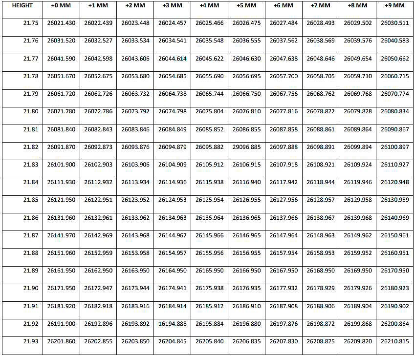
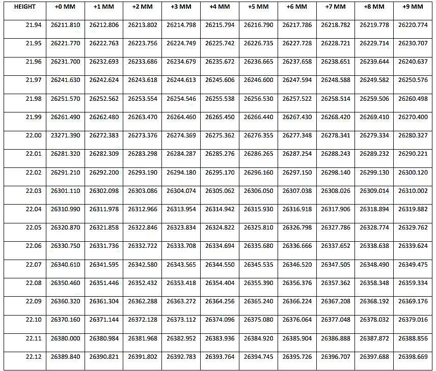
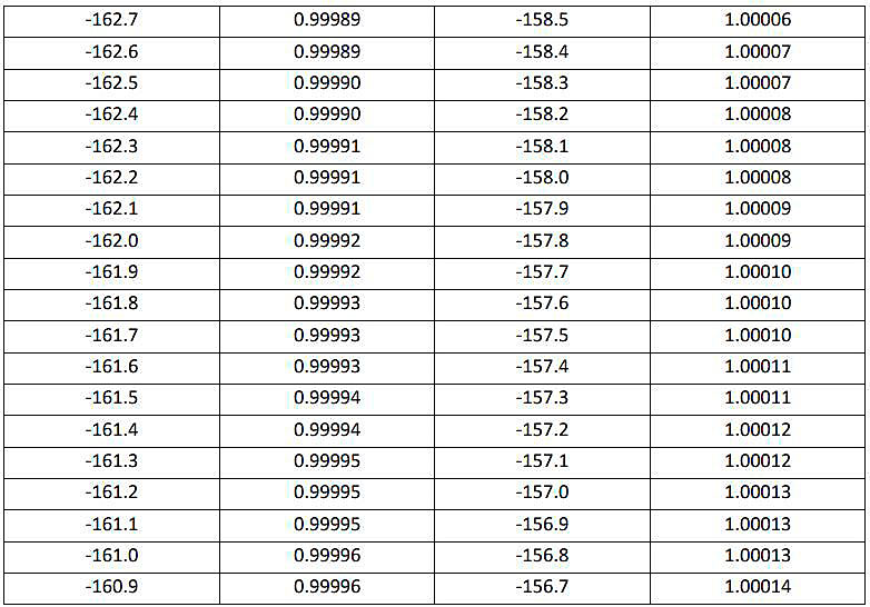
For each LNG carrier there is one main gauge table per tank. Generally, the volumes are given for heights varying cm by cm, the volume for intermediate heights in mm being calculated by interpolation. An example of a gauge table is given in table below.
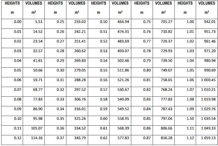
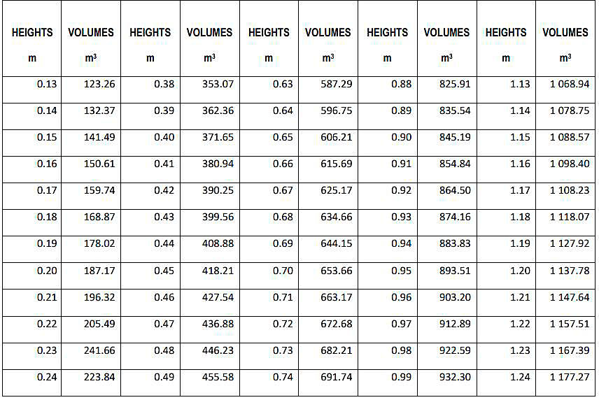
Total volume: 25 577,680 cubic meters.
To avoid these interpolations, which can be a source of inaccuracy, the most-used parts of the gauge tables – i. e., heights between 10 and 60 cm and heights corresponding to a volume between 95 % and 98 % of the total volume of the tank – are sometimes developed in a fine gauge table and the volumes can be calculated mm by mm. This then reduces the determination of the volume to a more reading in a table (see below).
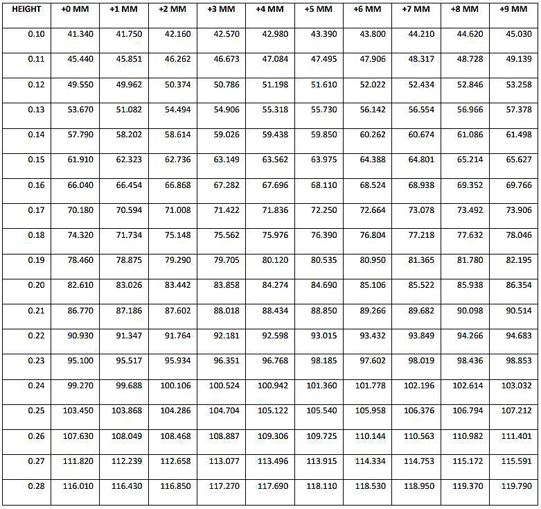
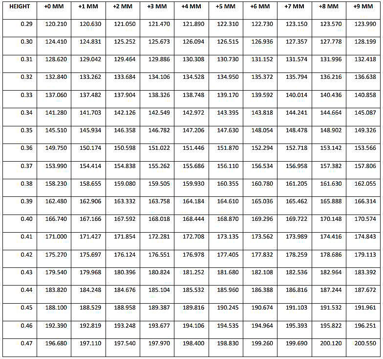
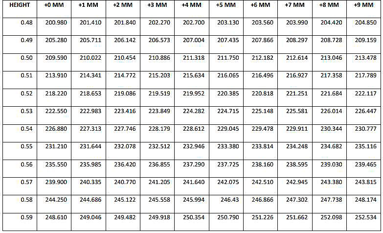
Heights are in meters, volumes in cubic meters.
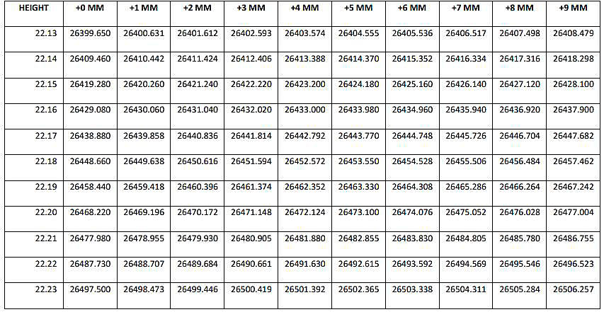
Heights are in meters, volumes in cubic meters.
The examples used in this section are taken from a vessel with prismatic cargo tanks. The same principles generally apply to those vessels with spherical or other shapes of cargo tanks.
Various methods exist for establishing the gauge tables. The main methods are:
- macro metrology with tapes;
- a laser measuring system;
- a photogrammetric measuring system.
For details of calibration procedures for tanks, reference can be made to existing ISO standards (see ENCLOSURE 2: LNG AND NATURAL GAS CUSTODY TRANSFER METHODS).
Correction tables
The gauge tables are completed with correction tables established according to:
- the condition of the LNG carrier (trim/list);
- the average LNG temperature in the tank that influences contraction or expansion of the tank;
- the temperature in the gaseous phase, and/or the density of the LNG influencing the level measuring devices.
Tank gauge tables may also provide an example of how to conduct the volume calculation using the measurements provided.
It should be noted that LNG carriers normally have two level measurement devices in each General Overview of LNG Cargo Tanks (Typical Operations)cargo tank (and often of two different types). Correction tables are specific to a level gauge. Using the correction tables for the wrong gauge can result in significant inaccuracies.
Correction according to the condition of the LNG carrier. The gauge tables are established for an LNG carrier with zero list and trim. Therefore, it will be necessary to correct the height reading to take into account a list or a trim which is not zero.
Correction tables are made up according to:
- the position of the gauge in the tanks;
- the list of the LNG carrier (see Figure 1);
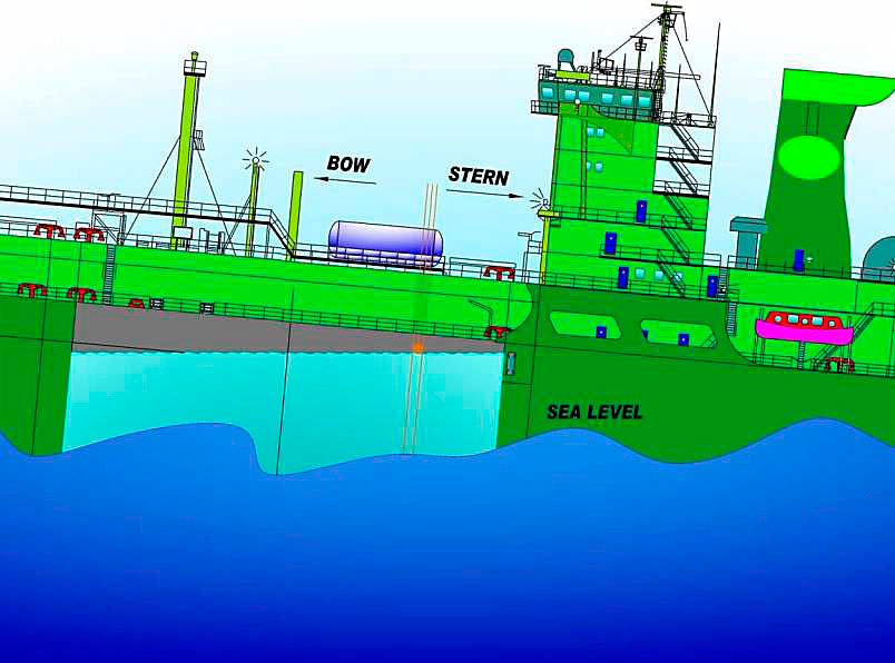
- the trim of the LNG carrier (see Figure 2).
These corrections can be positive or negative. So, the real height will be equal to the algebraic sum of the height reading, the correction for list and the correction for trim. These tables are made up in degrees for the list and in meters for the trim, with fixed steps of variation. For intermediate values, the correction will be calculated by interpolation.
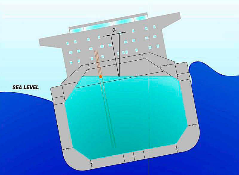
In practice, the LNG carrier’s cargo officer will usually manage the vessel’s ballast to obtain zero or a limited list and trim.
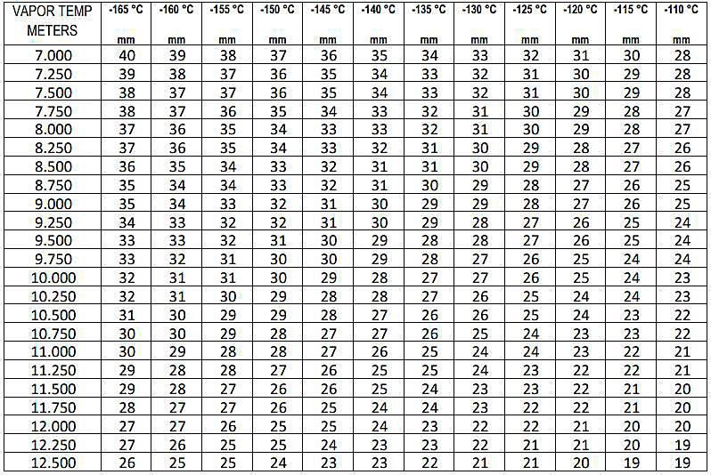
Corrections according to the temperatures in the liquid and gaseous phases. The corrections are related to the volume variations resulting from the contraction of the tanks and their insulation according to the temperature of the liquid and gaseous phases.
This phenomenon is significant for LNG carriers with self-supporting tanks. An example of these tables:
Approval by authorities
The gauge tables may be approved by either the authorities of the countries concerned with the LNG sale and purchase or by independent sworn measurers. In practice, largely due to the importance for LNG shipping of the Japanese market and its requirement for NKKK certification, the great majority of LNG carriers have such certification.
This approval may be valid for a limited duration, generally 10 to 12 years, or less depending on LNG terminal requirements, provided there are no modifications to the tanks. For the European Union, this approval corresponds to a community directive.
When an LNG carrier is put into operation, a list of all works on the tanks must be supplied, and the tanks must be inspected for any modifications which might affect the volume.
In the case of any distortion or modification to a tank, the gauge table must be adjusted accordingly.
The applicable and confirmed standards correspond to:
- ISO 8311:2013 Refrigerated light hydrocarbon fluids – Calibration of membrane tanks and independent prismatic tanks in ships – Physical measurement.
The correction is negative or positive depending on whether the bow of the LNG carrier is deeper in the water or otherwise. In this illustrative case the correction will be positive.
Instruments and methods for measuring the level of liquid in the LNG carrier’s tanks
Main liquid level gauging devices
The main types of gauges are:
- electrical capacitance type gauge;
- float type gauge;
- radar type gauge;
- laser type gauge: a recently developed system.
Currently ISO 18132-1:2011 and ISO 18132-2:2008 are valid for the above-mentioned level gauging devices.
Any of these gauging systems can serve as main instrument for liquid level measurement inside an LNG cargo tank. Usually (but not always) two or sometimes even three types of the above-mentioned systems are installed in each cargo tank of the LNG carrier. One of these should be agreed as the main (primary) level gauging device by buyer and seller. The standby or back-up gauging system(s) is (are) to be considered as the auxiliary (secondary) gauge systems.
A few LNG shipping agreements do not specify the type and only specify the required accuracy (e. g., ± 5,0 mm or better). On old ships other systems may be found, such as nitrogen bubbling devices, but the accuracy of these is generally lower and requires a good knowledge of the actual LNG density in the cargo tank.
Accuracy may be verified at the time of gauging, as follows:
- for electrical capacitance type gauges, by an on-line validation system;
- for radar type gauges, depending on the design, either by a verification pin or by comparison with the determined length of each still pipe segment;
- for float type gauges, either by comparison with the other gauging system or the stowed/grounded instrument’s level readings.
For the measurement of liquid levels in terminal berths exposed to the open sea, filtering systems approved and accepted by sworn surveyors as suitable to be integrated in CTS operations may be considered. These filtering systems were specifically developed for offshore use where large level fluctuations may be experienced. ISO 10976:2012 includes information on these systems.
Electrical capacitance type level gauge. The electrical capacitance gauge (see Figure 3) consists of two concentric tubes made of aluminium or stainless steel, depending on the construction of the LNG cargo tank.
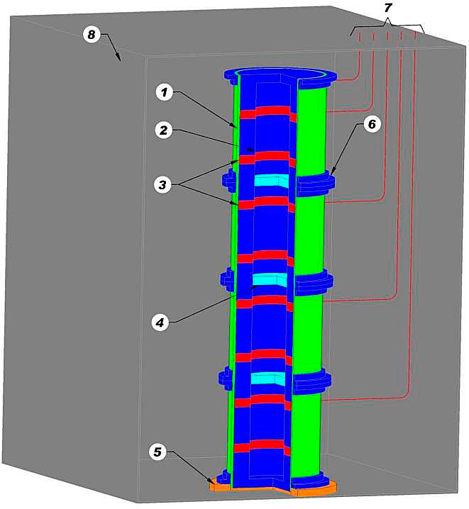
1 – Outer tube; 2 – Inner tube; 3 – Concentric electrical insulator; 4 – Isolation of inner tube sections by a gap or dielectric plug; 5 – Isolation from the tank bottom; 6 – Connections between the sections of the outer tube to make a single electrical conductor; 7 – Data signal connections from the gauge to the junction box outside the cargo tank; 8 – LNG cargo tank
The inner tube is supported by the outer tube by means of concentric insulators placed at regularly spaced intervals along the whole length of the tubes. The resulting assembly forms a series of cylindrical capacitors, having the same total height as the cargo tank of the LNG carrier.
The LNG, according to its level, will fill the space between the concentric tubes. The liquid affects the dielectric characteristics of the capacitors formed by the tubes such that, by measuring the change in capacitance, the height of the LNG in the annular space, and hence the level in the tank, can be determined. The contraction of the tube assembly at low temperature may be taken into account to correct the level measurement.
The accuracy of the measurement resulting from the calibration of the dimensions and the linearity of the capacitor and of the electronics should be, for the gauge as a whole, ± 5,0 mm.
Float type level gauge. Measurements are made with a float hanging on a tape or a ribbon (see Figure 4).
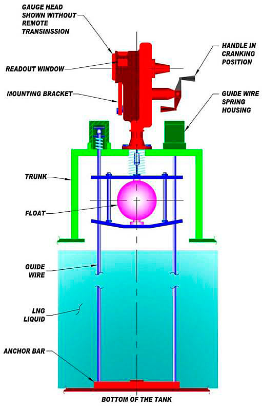
According to the level of the liquid, the float is displaced, and the tape or the ribbon on which it hangs is unrolled or rolled up on a drum whose rotation is recorded. This enables the position of the probe, and thus the level of liquid in the tank, to be known.
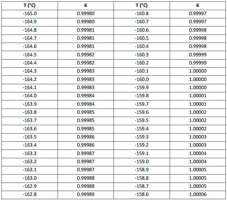
With float gauges, it is necessary to take into account the shrinkage of the ribbon, according to the temperature of the gaseous phase and the height of the liquid, and the density of the LNG, which will influence the float buoyancy. The correction tables will tabulate the corrections for these effects.
The corrections for temperature are required only in the case of a stainless steel ribbon. In the case of an invar ribbon, the shrinkage is much less and is generally considered as negligible.
The accuracy of this type of gauge, designed for marine application, is in the range of ± 4 mm to ± 8 mm.
Radar (microwave) type level gauge. The radar or microwave type gauge works on the same principle as a ship’s radar (see Figure 5).
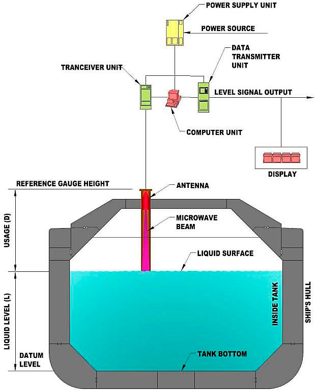
A transmitter/receiver is mounted on the top of the cargo tank and emits microwaves vertically down towards the surface of the liquid. The signal is reflected from the surface, received by the transmitter’s antenna and sent back to the control panel. The signal is then processed to determine the distance of the liquid surface from the transmitter and hence ullage. One or more certified transmitters/receivers are usually carried as spares in the event of a failure of this equipment.
Since all the level detection components are mounted external to the cargo tank, the microwave system allows for the possibility of changing the gauge in service.
The radar gauge requires a wave guide which is like a stilling well. However, this well is a critical and complex component resembling a gun barrel.
There are several types of gauging pipes used for microwave type CTS level gauges. Particular attention should be paid to bottom attenuators, which can limit minimum gauging height and therefore accuracy due to their mountings.
The accuracy of this type of gauge can be ±5,0 mm or better.
Laser type level gauge. The laser-based sensor technology (LiDAR) is a recently introduced gauge type.
The laser unit is installed above the deck, isolated from the tank by a sight glass and targeting the liquid level surface with a low power laser beam. This beam is protected from adverse influences on its measurements arising from within the tank by an ordinary stilling well. The stilling well used on a laser-based system is not used as a wave guide; its construction is simple, and it remains relatively inexpensive.
The time interval between the transmitted and received pulses is accurately measured and processed to determine the distance of the liquid surface from the transmitter and hence the ullage height.
The level measurement remains unaffected by changes in the LNG composition or by the changes in physical properties of the still pipe. When performing level measurements at the bottom of the tank, echoes or reflections near the bottom do not affect the accuracy of the system. The gauge will also register a dynamic change in the LNG level. The accuracy of this type of gauge is ±7,5 mm or better.
Timing of the level measurement
General guidelines are described in the standard ISO 6578 – Refrigerated hydrocarbons liquid – static measurement – calculation procedure.
It is important that the level readings are recorded in a static and closed condition of the LNG carrier, with no flow of either gas or liquid.
As far as practicable, the period between the time of measurement and start of cargo transfer should be narrowed to the minimum achievable. The same should apply for the final cargo custody transfer level measurement, once time is allowed to correctly drain cargo lines (as appropriate) and stabilize the liquid levels. The same temperature and inventory condition of the ship’s LNG cargo lines should be maintained during both opening and closing custody transfer surveys. Wherever it is intended that the vessel heels out (is completely emptied) and cargo lines are empty upon completion of discharge, it is necessary to ensure that the cargo lines are drained for sufficient time prior to the closing CTS, to ensure stabilization of the temperature of the lowest temperature sensor.
Readings
It is good practice that all readings are witnessed by both parties, buyer and seller. Each party should appoint a representative. A sworn surveyor may also be jointly nominated by both parties to stand as third and neutral party, and witness and record the CTS readings.
The readings of the levels of liquid in the tanks are taken after the readings of the list (port or starboard), and the trim (bow or stern) of the LNG carrier. All these readings will be taken into account in order to determine the corrected liquid level and hence the LNG volume in each of the cargo tanks. The temperatures of the liquid and the gaseous phase are also measured (see Selection principles LNG samples and temperature on tankers“Temperature measurement”). The absolute pressure in each LNG cargo tank is measured as well. If the pressure measurement is gauge instead of absolute, the atmospheric pressure is also read.
Parties should also agree in advance what actions are to be taken in the event of a failure of any part of the volume measurement system (e. g., consider secondary level gauging, manually calculate volumes with tank tables, etc.).
Reading of the level with float gauges. It is good practice that all float gauges are lowered to the liquid level well before any reading is taken. This should allow for sufficient time to cool down either the gauge ribbon or wire and to ensure shrinkage, if any, is stabilized. It is also good practice to verify that the calibration seals on the float gauge unit are intact.
Float gauges normally have two reference readings, upper and lower. The upper reading can always be checked. Depending on the manufacturer, this corresponds to a locked position of the float gauge in its stowed condition or a resting position of the float on the valve’s isolation gate. These reference readings are reported on the ship’s CTS calibration certificate and they are also stamped on a plate fixed to the gauge itself. It is advisable that the upper reference is checked before the cargo tank liquid levels are taken.
The cargo liquid level is never still, and a slight movement of the float is always to be expected. Even when the ship is not subject to any wave motion, the readings will always be an average level between upper and lower peaks of level readings.
If no fluctuation of the liquid level is detected, this may indicate a possible «sticking» of the float inside the gauge well. If this is the case, it is recommended that the float is moved up and down a number of times in order to free it and obtain reliable readings.
On occasions when the LNG carrier’s tanks are completely empty, the lower reference of the float can also be checked for correctness. This is usually called the float’s grounded position.
Whenever remote float readings are available in the ship’s control room, it should be checked that these are approved for commercial transactions before they can be used for CTS purposes. Float gauges are always stowed in their fixed upper position when sailing so that the ribbon or the tape does not break due to liquid movements.
Reading of the level with capacitance and radar gauges. The methods of reading are normally agreed between the seller and buyer. Usually, the observed cargo tank level is averaged over 5 readings taken at specified and regular intervals.
The above method may not be suitable for LNG terminal berths exposed to the open sea because of the high fluctuations of the liquid levels. To cope with this, some custody transfer measurement systems manufacturers have lately developed filtering systems in order to average the level fluctuations and provide a realistic liquid level (see above).
Level readings are normally available in the ship’s cargo control room and sometimes in an instrumentation room located in the accommodation block.
Some modern on-board CTM systems use computer to process all the information, including averaging the (5) level readings over time, temperature and pressure, and draw on digital gauging tables to produce a printed document containing all the ship-generated information required for the custody transfer. However, these seldom include «gas displaced» or «gas to engine room», if applicable.
Correction of readings
Float gauge. The readings made on the measurement appliances should be corrected according to:
- list;
- trim;
- density of LNG, affecting float buoyancy;
- coefficient of contraction of the material and the insulation of the tanks; this coefficient is more relevant in the case of self-supporting tanks (see higher);
- temperature of the gaseous phase if the ribbon or cable is not made of invar;
- standard and fixed corrections if applicable.
The corrections are made using specific tables for each of the above corrections.
Capacitance, radar and laser gauges. In this case, only the corrections for list, trim and the contraction of the tanks are normally taken into consideration. For accurate level measurement the contraction of the capacitance gauge at low temperature may also need to be considered.
Two main types of radar (microwave) gauges are currently available. One type is based on the principle of estimated velocity of the microwaves inside an atmosphere of predetermined hydrocarbon composition. Within the worldwide range of commercially available LNG compositions this has little impact on the overall accuracy of the gauge except for nitrogen content in the vapor which may significantly alter wave velocity and should be considered.
One available type of microwave gauge uses several defined targets made of PTFE (Teflon®) at known positions along the stilling pipe. This enables the system to precisely calculate the microwave propagation speed and adapt it to locate the liquid level. The PTFE target position is usually known at +20 °C. In order to determine the wave propagation speed, the position of the targets is corrected according to the shrinkage of the still pipe, which is calculated as a function of the vapor phase temperature above the liquid level.
As to correction of readings for laser gauges, please refer to Mastering LNG Measurement – Essential Practices and Operational Insights“LASER TYPE CARGO TANK LEVEL GAUGE”. Modern computer-based systems usually can accept trim and list data either manually or from external sensors and automatically apply the corrections. However, it is important to compare the observed trim/list to the data from the trim/list independent sensor.
Depending on the sensor’s location, either sagging or hogging of the LNG carrier may seriously affect the accuracy of the readings.
Use of spare level gauge
When the main or primary level gauge cannot be used, the spare level gauge, also called the secondary level gauge, is used to measure the level of LNG. Therefore, it should always be in operation. Usually, the secondary level gauge will also be calibrated and certified. However, if the calibration tables of the LNG carrier are available only for the main level gauge, a conversion table is required in order to take into account the respective locations of main and secondary gauges, or the statistical differences between the two-level gauge measurements, and to evaluate the corresponding corrections which must be applied to level measurement before using the calibration tables.
Since it is possible that the primary level gauging system could fail during the cargo transfer operation, and since it is strongly recommended to use the same reference system at both opening and closing CTS measurements to determine the cargo volume transferred, it is therefore advisable that both primary and auxiliary level gauging systems readings are recorded at the opening CTS measurement, before the start of cargo transfer operations. It should also be ensured that the spare level gauge is maintained within stated accuracy at all times.
Complete unloading (tank stripping)
Cargo tank stripping with stripping pumps:
- the LNG carrier needs to be able to continue discharging once the cargo pumps cannot longer be kept running because the level in the cargo tank is too low;
- these stripping operations require several additional hours at the port. Stripping to lowest levels is generally conducted prior to scheduled dry-docking or for spot cargo operations;
- the remaining quantity after stripping can be vaporized by warming up to a temperature at which the LNG carrier is considered to be empty of LNG e. g., -80 °C (no more liquid ethane) or -40 °C (no more liquid propane). The vaporization of residual LNG is typically conducted not at berth but at sea, after the unloading is finished and the vessel has left the berth.
For the complete or nearly complete unloading of an LNG carrier with prismatic tanks, depending on the membrane type, the ship should be trimmed to the best condition to achieve effective stripping and a reliable level reading at the end of operations. In general, LNG carriers with prismatic tanks require the ship to be trimmed by stern in order to achieve complete or nearly complete unloading of cargo. Depending on the membrane type, higher trim levels will also result in more effective cargo tank stripping provided that care is taken not to exceed neither ship nor Terminal limitations, if any in place. Whatever the primary membrane configuration, some LNG liquid will, however, always remain in the cargo tank and that needs to be quantified. It is essential that, as much as possible during the stripping operation, the liquid level is always within the certified minimum gauging height. e. g. using onboard CTMS or cargo tank tables using appropriate correction tables. In the event the liquid level falls outside the certified minimum gauging height, buyer and seller should agree on the immeasurable cargo quantity.
The energy of this remaining LNG transferred either in the liquid or in gaseous form can also be determined by mutual agreement by the parties taking into account any technical limitations they may have.
Note. Certain parties have raised concerns over the possibility of having a quantity of LNG unaccounted for during closing of CTS under a positive trim as a result of LNG being trapped in the bottom part of uncovered corrugations of MARKI/MARKIII membrane systems, where small liquid wedges may form between the tank’s bottom plate and the transverse corrugation in each of the exposed tank’s bottom cells. The validity and extent of such liquid entrapment is currently unknown. This will require further and full investigation by independent and expert parties, before any conclusion can be made on the subject. The conclusion of such investigation should then be fully endorsed and certified by independent and recognized sworn surveyors.
Automated systems
The LNG carrier may be fitted with an automatic system for the calculation of LNG and gas volumes in each tank. The use of such a system, commonly referred to as the ship’s custody transfer measurement system (CTMS) will facilitate the process of determining quantities transferred during loading and unloading.
The CTMS processes data from tank level, temperature, Wave and Impact Loads in Design of Large and Conventional Liquefied Gas Carrierspressure sensors, etc. in real-time, taking into account the required corrections and certified gauge table, to produce a calculation of volumes before, during and after transfer. By taking measurements frequently, data can be averaged to improve repeatability of the calculation.
Modern custody transfer measurement systems typically comprise two discrete parts:
- (a) the tank gauging system providing corrected tank levels, temperatures and pressures;
- and (b) workstation(s) and peripherals, usually located in the ship’s cargo control room, to perform the volume calculation and generate reports.
Prior to such systems being entered into service, the calculation, including corrections and gauge tables programmed into the system, should be certified as accurate by an independent and competent third party, see above. Once the software has been verified, the calculation method may be regarded as reliable so long as the software is unchanged. Software modification may necessitate re-certification. It should also be recognized that the sensors have to be recalibrated at agreed intervals to ensure that input data is accurate, see Mastering LNG Measurement – Essential Practices and Operational Insights“Periodic instruments recalibration”.
Custody transfer measurement systems may be capable of correcting for trim and list both manually (by operator input of draught readings) and automatically (by sensor data). The method should be agreed between buyer, seller and terminal operator. Trim and list sensors cannot be readily recalibrated once in situ so manual methods are often preferred. Due attention should be given to the proper location of the trim/list gauges on board the vessel. If due to an inappropriate location these gauges are influenced by the position of the vessel, this may affect the accuracy of the instrument.
Read also: LNGC Project Factors and Cargo Containment System
It is appreciated that a software-based calculation may be less transparent to the buyer, seller, and terminal operator than more traditional methods. The CTMS as a whole should be dependable in use. In addition to software verification, due regard should be given to hardware availability, reliability and maintainability to minimize the likelihood and consequence of failures in use.
It is recommended that instruments are connected directly to the system, i. e., sensor data cannot be manipulated by other systems unless part of the certified arrangement. Furthermore, computers (PC, process controllers), data communication links (serial, network) and peripherals (screens, keyboards, printers) should not, in general, be shared with other applications in order to maintain data integrity. However, a copy of the calculation software may be hosted on a shared workstation as a back-up to the primary system.
Data used in the transfer process, such as tank levels, may be transmitted from the CTMS to other ship’s control and monitoring systems providing this does not influence the custody transfer calculation. In general, data should not be transmitted to the CTMS from other systems unless it is part of the certified arrangement.
Custody transfer measurement systems are typically able to produce printed reports indicating volumes before and after transfer. However, the ability to automate this part of the custody transfer survey does not obviate the need to provide, if required, the information required to carry out the calculation manually.
Calculation of the volume of LNG transferred
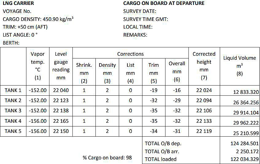
This calculation is illustrated by an example given below showing the results of the volume determination before and after loading the LNG cargo, with the following assumptions:
- a «Gaz Transport» – type LNG carrier with 5 invar membrane prismatic tanks;
- in each tank, one float gauge with a stainless steel ribbon.
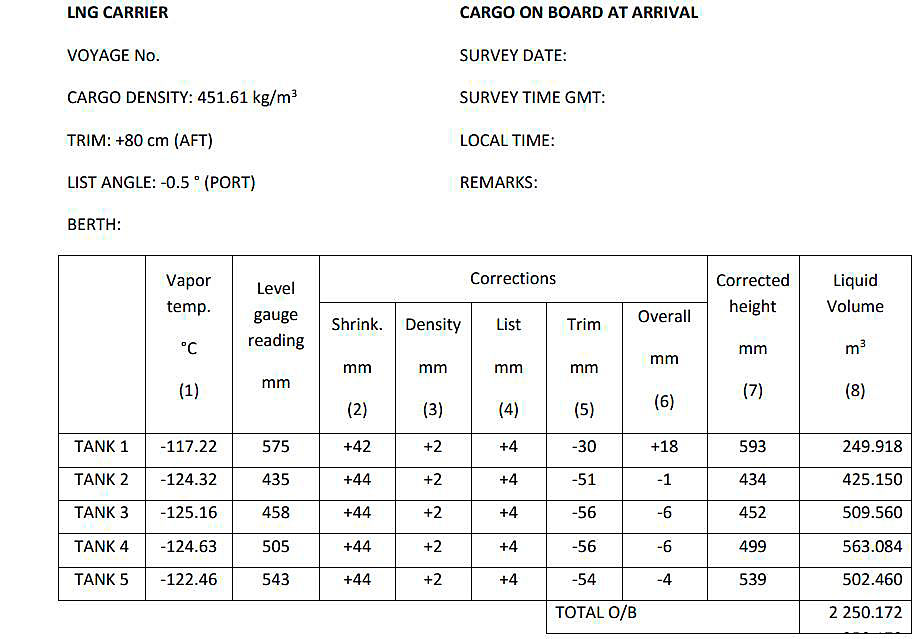
Notes:
(1) For measurement of temperature in the gaseous phase.
(2) Correction for ribbon shrinkage of the float level gauge due to the cryogenic temperature in the gaseous phase according to Table. The correction shrink is generally referred to as tape correction. On Moss ships, there is also a correction called shrinkage factor.
(3) Correction for LNG density, established from the density calculated on the basis of the LNG composition, according to (4).
(5) Table.
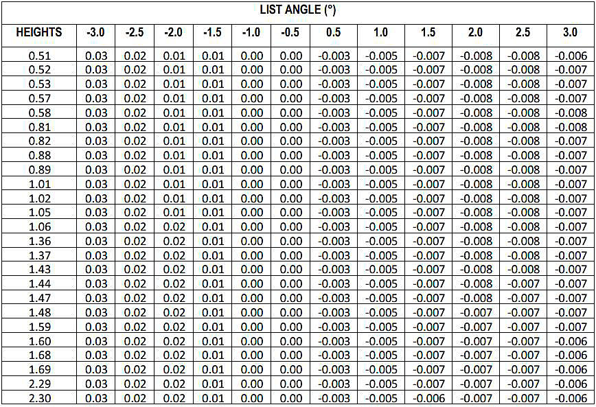
(6) Correction for the list corresponding to the liquid height according to the correction tables, an example of which is shown in Table A-15 for tank. In this case the position of the gauge is at the starboard side of the ship’s centre line.
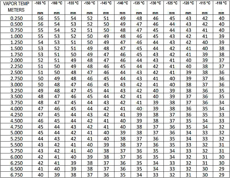
(7) Correction for the trim corresponding to the liquid height according to the correction tables, an example of which is shown in Table higher (an interpolation was made in this case between the correction values for a 50 cm and a 100 cm trim). In this case the position of the gauge is on the stern-side of the sideline of the tank.
(8) Algebraic sum of corrections (2), (3), (4) and (5).
(9) Corrected height resulting from the algebraic sum of the five previous columns.
(10) Determination of the liquid volume given in the calibration tables from the corrected height. These tables are established for heights varying mm by mm, see example in Table higher on the basis of certified tables indicating volumes for heights varying cm by cm. An example is given in Table higher for the empty and for the full tank.
Notes (1) to (8): see table above.
The float gauges have been adjusted to read correctly with the float floating in LNG of a density of 470 kg/m3.
The following table gives corrections to apply to the float gauge readings when floating in liquids of densities other than 470 kg/m3.
| DENSITY (kg/m3) | CORRECTIONS (mm) |
|---|---|
| 450-452 | +2 |
| 453-462 | +1 |
| 463-472 | 0 |
| 473-482 | -1 |
| 483-493 | -2 |
| 494-505 | -3 |
| 506-516 | -4 |
| 517-529 | -5 |
| 530-542 | -6 |
| 543-550 | -7 |
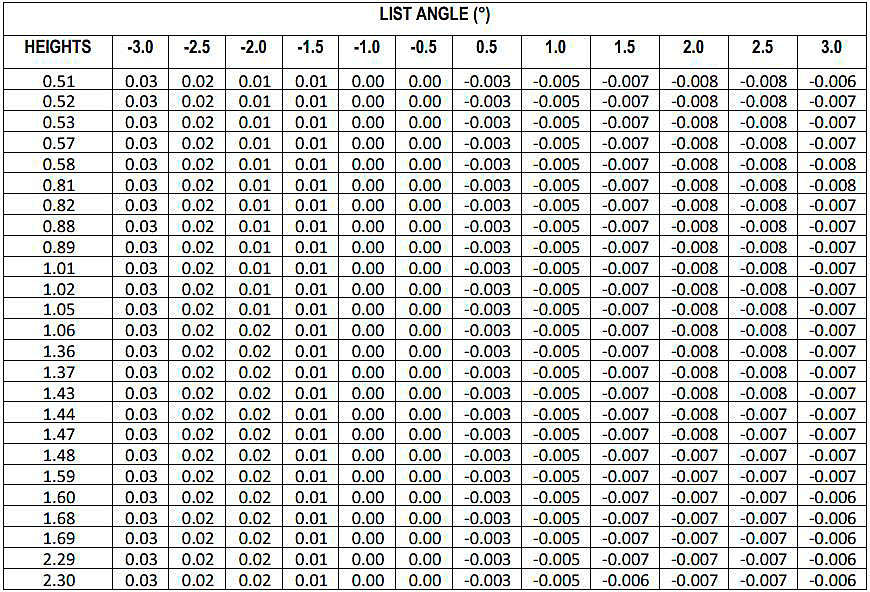
The list angles are in degrees, negative values to port, and positive values to starboard.
Heights and corrections are in meters.

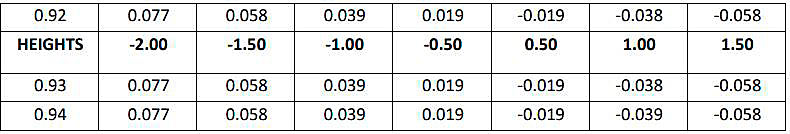
The trim values are in meters, negative values fore, positive values aft.
The heights and the corrections are in meters.
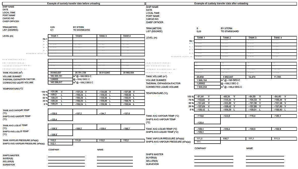
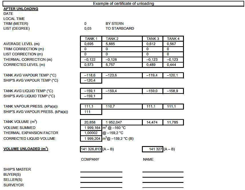
The example as illustrated is representative of an LNG carrier with an older level gauging system. In order to calculate the volume transferred, two conditions are required, knowledge of the total cargo volume on board (a) before the start of cargo transfer operations and (b) after these cargo transfer operations are completed. These two conditions are either manually recorded or directly produced and printed out by a computer if available. Details of each cargo tank parameters must be logged. In order to document a cargo transfer operation, modern primary custody transfer measurement systems produce three printouts, a so-called «before loading/discharge» cargo tanks status, an «after loading/discharge» cargo tanks status and a third printout just after the «after loading/discharge» condition; which is usually referred to as the «Certificate of Loading/Discharge». This third printout summarizes the general parameters of the two conditions and shows the volume transferred by comparing the initial and final cargo volumes. An example of Custody Transfer Survey documents for an unloading of an LNG vessel is given below.
It is essential that the LNG carrier’s pipework and manifolds are kept as far as practical in the same inventory condition at the opening and closing Custody Transfer Surveys.
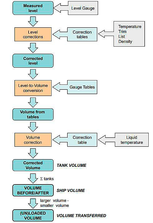
Figure 6 illustrates the calculation procedure to determine the volume of LNG transferred based on the ship’s measurements.