Discover the intricacies of LNG measurement, from calculating energy transfer to operational procedures. Explore standardization, partial loading/unloading, and critical gassing-up and cooling down operations in this comprehensive guide.
Following the publication in 1985 by the NBS of its study “LNG Measurement – A User’s Manual for Custody Transfer“, the Executive Committee of the GIIGNL (Groupe International des Importateurs de Gaz Naturel Liquéfié) considered it would be useful to write a handbook, as simple and as practical as possible, aimed at organizations involved in the measurement of the energy transferred in the form of LNG in the context of a LNG purchase and sales agreement, whether this sale be FOB [Port of loading], DES or CIF. [Port of unloading].
During its session of October 1987, the General Assembly of GIIGNL decided that this practical handbook should be drawn up by a Study Group comprising companies of the GIIGNL and coordinated by Distrigas S. A (B).
The methods described in this handbook could serve to improve existing procedures. They could also be used in purchase and sales agreements for the GIIGNL members and serve as a reference in new import agreements.
This handbook is based on the measurement methods most used by GIIGNL members.
Detailed tests of the apparatus used can be found in “LNG Measurement Study” of NBS.
We wish to thank the companies:
- BG (UK);
- Distrigas Boston (USA);
- Enagas (E);
- Kansai Electric Power Co (JP);
- Snam (I);
- Tokyo Electric Power Co (JP);
- Tokyo Gas Co Ltd (JP);
- Ruhrgas (D);
- CMS Energy Trunkline LNG (USA);
for their cooperation in producing this handbook, and more particularly Gaz de France for drawing up Selection principles LNG samples and temperature on tankers“Sampling of LNG” and Gas analysis of LNG on tankers“LNG analysis for quality and measurement impurities” of this handbook and Osaka Gas Co Ltd for coordinating the studies of the Japanese companies.
SECOND EDITION, OCTOBER 2001. Following the publication of the ISO 13398:1997 standard “LNG – Procedure for custody transfer on board ship“, the GIIGNL General Assembly requested the GIIGNL Study Group to revise the original edition (March 1991) of this GIIGNL LNG Custody Transfer Handbook, particularly taking into account this new ISO standard.
All articles have been reviewed and updated where appropriate. The following sections have been thoroughly revised:
- 2. General description of the measurement;
- 3. Volume measurement;
- 6. Sampling of LNG;
- 7. Gas analysis;
Moreover, a new section was added:
- 14. LNG Sales contract custody transfer checklist.
Worked out examples for LNG density and GCV have been rearranged in “USE OF IN-LINE
MEASUREMENT OF LNG FLOW” and:
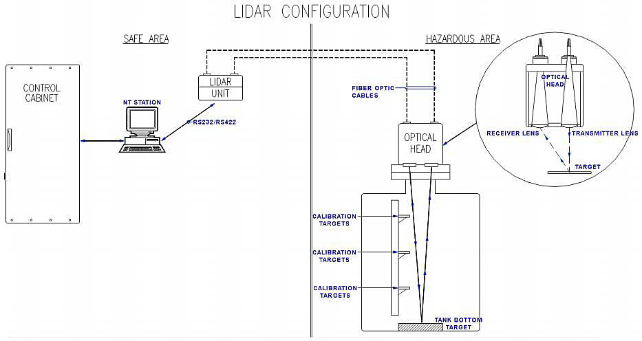
LASER TYPE CARGO TANK LEVEL GAUGE
The principle of laser type level gauge is based on a dual transmitter (optical head) composed of an emitter and a receiver, mounted on the top of the cargo tank. The emitter sends a laser beam down towards the surface of the liquid; the signal is reflected from the surface, detected by the receiver cell and send back to the unit control. The system is calibrated at several target levels of the tank.
The first commercial application and certification of this new laser-based technology was in late 2005 following a R&D effort on board the vessel «Le Tellier». NKKK certification for the system with an accuracy up to ±7,5 mm was granted in November 2005.
Accuracy:
- Measurement range – 0-50 m;
- Resolution – 1 mm;
- Accuracy better – ±7,5 mm or;
Features:
- On-line accuracy verification.
- Temperature, pressure, trim and list corrected.
- Serial communication.
- No in-tank equipment.
We wish to thank all companies and organizations and their delegates who together contributed to this second edition, viz. (in alphabetical order):
- Advantica Technologies Ltd. (UK);
- BG International (UK);
- CMS Energy Trunkline LNG Company (USA);
- Distrigas (B);
- Enagas (E);
- Gaz de France (F);
- Nigeria LNG (NI);
- NKKK (JP);
- Osaka Gas (JP);
- Rete Gas Italia (I);
- SIGTTO (UK);
- Tokyo Gas (JP).
Tractebel LNG North America (USA).
THIRD EDITION, MARCH 2010. Since the second edition, several new international standards and revisions of existing international standards related to the subject of this handbook, have been published or are forthcoming. Also, technologies and best current practices evolved in this past period. Therefore, the GIIGNL General Assembly requested the GIIGNL Technical Study Group to revise the second edition (October 2001) of the GIIGNL LNG Custody Transfer Handbook, with the upcoming new ISO standard ISO 10976 «Measurement of cargoes on board LNG carriers», which will replace and supersede the current ISO 13397 (1997) standard upon its publication.
Moreover, this third edition of the handbook has been updated and revised as appropriate to streamline it with new or revised international standards such as ISO, EN and other standards. These include:
- EN 437: Test Gases – test Pressures – Appliance Categories – Edition 2003;
- ISO 8943 Refrigerated light hydrocarbon fluids – Sampling of liquefied natural gas – Continuous and intermittent methods – Edition 2007;
- ISO 6974-6 Natural gas – Determination of composition with defined uncertainty by gas chromatography – Part 6: Determination of hydrogen, helium, oxygen, nitrogen, carbon dioxide and C1 to C8 hydrocarbons using three capillary columns – Edition 2002;
- ISO 16664: Gas analysis – Handling of calibration gases and gas mixtures – Guidelines – Edition 2004;
- ISO 4259: Petroleum products – Determination and application of precision data in relation to methods of test – Edition 2006;
- ISO/TR 24094: Analysis of natural gas – Validation methods for gaseous reference materials – Edition 2006;
- ISO 10723: Natural gas – Performance evaluation for on-line analytical systems – Edition 2002;
- ISO 6326-1: Natural gas – Determination of Sulphur compounds – Part 1: General introduction – Edition 2007;
- ISO 6327: Gas analysis – Determination of the water dew point of natural gas – Cooled surface condensation hygrometers – Edition 2007;
- ISO 19739: Natural gas – Determination of sulphur compounds using gas chromatography – Edition 2004;
- ISO 12213-1 -2 -3: Natural gas – Calculation of compression factor – Edition 2006;
- ISO 15112: Natural gas – energy determination – Edition 2007;
- ISO 18132-1: Refrigerated light hydrocarbon fluids – General requirements for automatic level gauges – Part 1: Gauges onboard ships carrying liquefied gases – Edition 2006;
- ISO 18132-2: Refrigerated light hydrocarbon fluids – General requirements for automatic level gauges – Part 2: Gauges in refrigerated-type shore tanks – Edition 2008;
- ISO/DIS 28460: Petroleum and natural gas industries – Installation and equipment for liquefied natural gas – Ship to shore interface and port operations – Edition 2009.
All 14 sections, enclosures and appendices of the second edition have been exhaustively reviewed and updated where appropriate.
We wish to thank all 20 companies and organizations and their delegates who together contributed to this third edition, in alphabetical order:
- ActOn LNG Consulting – UK;
- Botas – Marmara Ereglisi – Turkey;
- BP – Sunbury-on-Thames – UK;
- Distrigas of Mass. – GDF Suez – Everett (Boston) USA;
- Dragon LNG – Milford Haven – UK;
- Elengy – GDF Suez – Paris – France;
- Enagas – Spain;
- Exxon Mobil – Houston – TX – USA;
- Fluxys LNG – Zeebrugge – Belgium;
- Gas Natural – Madrid – Spain;
- GL – Noble Denton – Loughborough – UK;
- Kogas – Seoul – South Korea;
- National Grid – Grain LNG – UK;
- Osaka Gas – Osaka – Japan;
- Shell Global Solutions – The Hague – The Netherlands;
- RasGas – Ras Laffan – Qatar;
- REN Atlantico – Sines – Portugal;
- Sempra LNG – San Diego – CA – USA;
- SGS – Belgium;
- SIGTTO – London – UK;
- Tokyo Gas – Tokyo – Japan;
- Total – Paris – France.
FOURTH EDITION, FEBRUARY 2015. Due to the rapidly changing market conditions, new (commercial) opportunities arise leading to new technical solutions and different operations (such as partial unloading, reloading at an LNG import terminal, ship-to-ship LNG transfer operations, development of the small scale LNG market not only with much smaller LNG ships and in much smaller quantities, but also with a different ship design and other cargo containment systems), the GIIGNL General Assembly requested the GIIGNL Technical Study Group to review and update the third edition (version 3.01 – March 2011) of the GIIGNL LNG Custody Transfer Handbook.
Furthermore, there is a continuous evolution in the LNG (sampling) technology and this fourth edition tries to incorporate and be in line with new or revised international standards.
All sections, enclosures and appendices have been thoroughly reviewed, amended and updated where appropriate. To make this handbook more readable, most of the examples have been replaced to the appendices. Moreover, all sections with regard to the uncertainty of the energy determination have been moved to Recommended methods for calculating LNG“Cargo Liquid Lines” and the following sections have been added:
- Mastering LNG Measurement – Essential Practices and Operational Insights“Gassing-up and cooling down operations”;
- Recommended methods for calculating LNG“Rounding of numbers and commercial impact” Rounding of numbers;
- Ship-to-ship LNG transfer operations“How is ship-to-ship LNG transfer operations on tankers” Ship-to-ship LNG transfer operations;
- Small LNG ship to shore transfer operations;
- Reloading operations in regasification terminals.
With regard to these Mastering LNG Measurement – Essential Practices and Operational Insights“Gassing-up and cooling down operations”, Ship-to-ship LNG transfer operations“How is ship-to-ship LNG transfer operations on tankers”, Ship-to-ship LNG transfer operations“Loading and unloading of small scale vessels” and Ship-to-ship LNG transfer operations“Reloading operations in regasification terminals”, the aim of this GIIGNL LNG Custody Transfer Handbook is to integrate the specific conditions for this special operations of gassing-up and cooling down, for ship-to-ship LNG transfer, for small LNG ship-to-shore transfer (or vice versa) and for reloading operations at regasification terminals, but not to integrate the small scale LNG transfer operations (such as bunkering or fuelling of ships and trucks, and filling of LNG trucks or containers).
We wish to thank all companies and organisations and their delegates who together contributed to this fourth edition, in alphabetical order:
- Botas – Marmara Ereglisi – Turkey;
- BG Group – Houston – Texas;
- Enagas – Spain;
- Fluxys LNG – Zeebrugge – Belgium;
- Gas Natural Fenosa – Spain;
- Gate Terminal – Rotterdam – The Netherlands;
- GDF Suez – Paris – France;
- National Grid – Grain LNG – UK;
- RasGas – Ras Laffan – Qatar;
- Shell Global Solutions – The Hague – The Netherlands;
- Tokyo Gas – Paris – France;
- Total – Paris – France.
FIFTH EDITION, FEBRUARY 2017. The fifth version comes as a quick follow-up and update of the fourth edition (February 2015). More than pointing at the differences and highlighting the points of attention when dealing with the relatively new operations of (un)loading small scale vessels and reloading operations at LNG import terminals, this fifth version provides answers and solutions for setting up (slightly) altered or new custody transfer procedures. It should be highlighted that the reason for these proposed changes is of truly technical nature and GIIGNL considers it as its duty to inform the LNG industry about this and its impact. Each stakeholder involved in the LNG custody transfer chain should determine whether or not a review of its contractual agreement(s) may be required.
We wish to express our appreciation and thanks to all companies and organisations and their delegates who together contributed to this fifth edition, in alphabetical order:
- Enagas – Spain;
- Engie – Paris – France;
- Fluxys LNG – Zeebrugge – Belgium;
- Gas Natural Fenosa – Spain;
- Gate Terminal – Rotterdam – The Netherlands;
- National Grid – Grain LNG – UK;
- Shell Global Solutions – The Netherlands & US;
- Statoil – Norway;
- Tokyo Gas – Paris – France.
SIXTH EDITION, MAY 2021. The sixth version comes as a quick follow-up and update of the fifth edition and includes, for the first time custody transfer for LNG truck loading: a new section has been added to integrate the specific conditions for truck loading, in particular the formula for calculating the LNG energy loaded and the instruments used for the measurements.
In addition, the sixth edition also contains the latest recommendations about the calibration and performance evaluation of chromatographs as well as some minor modifications.
We wish to express our appreciation and thanks to all companies and organisations and their delegates who together contributed to this sixth edition, in alphabetical order:
- Enagas – Spain;
- Elengy – Paris – France;
- Equinor – Norway;
- Fluxys LNG – Zeebrugge – Belgium;
- Gate Terminal – Rotterdam – The Netherlands;
- National Grid – Grain LNG – UK;
- Naturgy – Spain;
- Shell Global Solutions – The Netherlands & US.
General description of the measurement
Accuracy. The term «measurement accuracy» is defined in the most recent version of the International Vocabulary of Metrology (JCGM_200:2012) as «closeness of agreement between a measured quantity value and a true quantity value of a measurand». Measurement error is defined as measured quantity value minus a reference quantity value.
Uncertainty, combined standard uncertainty and expanded uncertainty. The terms «measurement uncertainty», «combined standard uncertainty» and «expanded uncertainty» (see Recommended methods for calculating LNG“Uncertainty of the energy transfer determination”) are used as defined in the JCGM 100:2008 document: «Evaluation of measurement data – Guide to the expression of uncertainty in measurement».
General formula for calculating the LNG Energy Transferred
The formula for calculating the LNG transferred depends on the contractual sales conditions. These can relate to several types of sale contract as defined by Incoterms 2010. In case of rules for sea and inland waterway transport, the most commonly used are an FOB sale, a CFR sale or a CIF sale.
In the case of a FOB (Free On Board) sale, the determination of the energy transferred and invoiced for will be made in the loading port. There is another sale contract similar to FOB, named FAS (Free Alongside Ship).
In the case of a CIF (Cost Insurance & Freight) or a CFR (Cost and Freight) sale, the energy transferred and invoiced for will be determined in the unloading port.
Other rules exist for any mode of transport which can hence also apply for maritime transport such as DAT (Delivered At Terminal) and DAP (Delivered At Place).
In FOB contracts, the buyer is responsible to provide and maintain the custody transfer measurement systems on board the vessel for volume, temperature and pressure determination and the seller is responsible to provide and maintain the custody transfer measurement systems at the loading terminal such as the sampling and gas analysis. For CIF and CFR (and DES according to Incoterms 2000) contracts the responsibility is reversed.
Both buyer and seller have the right to verify the accuracy of each system that is provided, maintained and operated by the other party.
The determination of the transferred energy usually happens in the presence of one or more surveyors, the ship’s cargo officer and a representative of the LNG terminal operator. A representative of the buyer can also be present.
An independent surveyor nominated and agreed between the parties involved shall witness or verify the verification/calibration certificates of all devices involved in the custody transfer, namely:
- On the (un)loading terminal: the gas chromatograph(s) and the reference gas certification(s);
- Onboard the vessel: level measurements, pressure measurements, etc.
Depending on the Terminal Rules of the delivery port, the calibration or verification may be done before and/or after the operations, or only periodically.
It is also recommended that the independent surveyor verifies the calibration certificates of the systems involved in the custody transfer on board the LNG vessel. The systems concerned are as follows:
- level measurements;
- pressure measurements;
- temperature measurements;
- trim and list measurement devices;
- gas meters (for engines, boilers and GCU);
- optional: Certificates of the calculation software.
The independent surveyor should have the same rights and obligations towards the parties involved, for which it is the mutual representative. The independent surveyor should not act as a consultant for any of the parties involved if there is a disagreement among the parties which it represents.
In general, the independent surveyor performs the transferred energy calculation according to the agreed terms and conditions and issues the final quantity report.
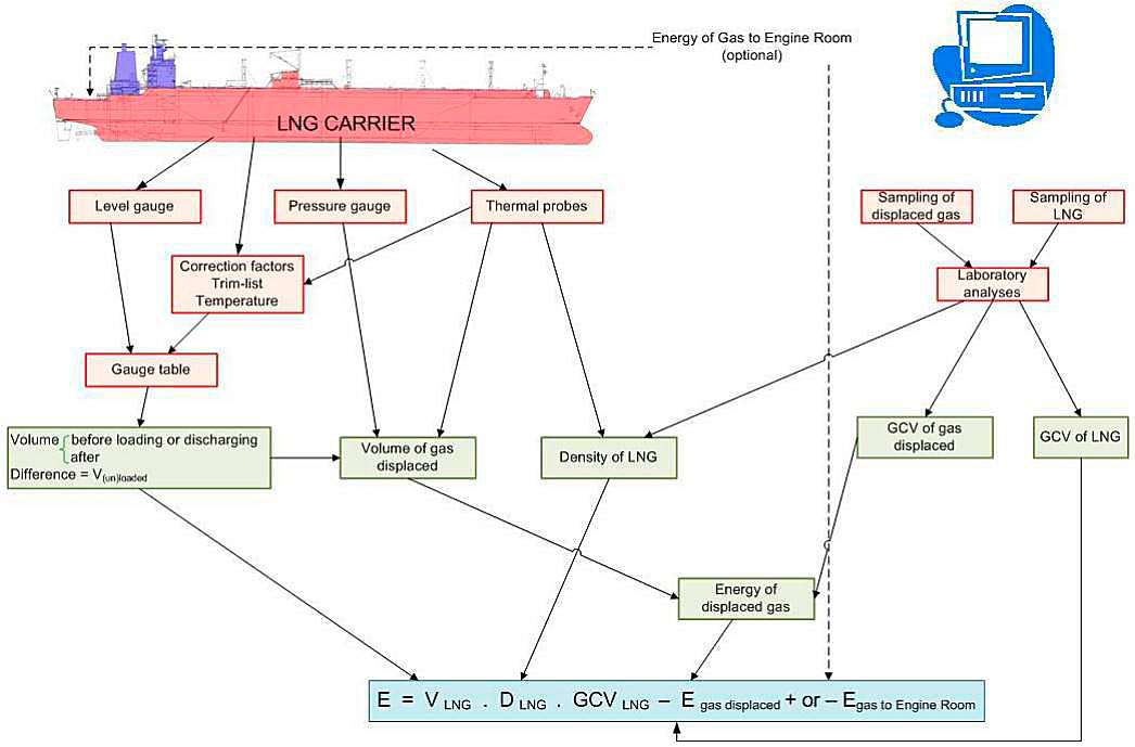
In all cases, the transferred energy can be calculated with the following formula:
where:
- E – the total net energy transferred from the loading facilities to the LNG carrier, from the LNG carrier to the unloading facilities or from one LNG carrier to another LNG carrier (ship-to-ship LNG transfer). In international LNG trading, the energy transferred is most frequently expressed in millions of British Thermal Units (106 BTU or MMBTU) although this is not a SI energy unit. Therefore, MMBTU is the preferred unit in this handbook. A conversion factor table for other commonly used energy units (such as MWh) can be found in table “CONVERSION FACTOR TABLE FOR ENERGY UNITS“;
- VLNG – the volume of LNG loaded or unloaded in m3;
- DLNG – the density of LNG loaded or unloaded in kg/m3;
- GCVLNG – the gross calorific value of the LNG loaded or unloaded in MMBTU/kg. The gross calorific value is generally used in international LNG trading rather than the net calorific value, see below;
- Egas displaced – the net energy of the displaced gas, also in MMBTU, which is either:
- sent back by the LNG carrier to shore or to another LNG carrier when loading (volume of gas in cargo tanks displaced by same volume of loaded LNG);
- or, gas received by the LNG carrier in its cargo tanks when unloading in replacement of the volume of discharged LNG;
- or, the volume of LNG that has been replaced by gas (even without a vapor connection to shore or another vessel).
- Egas to ER – if applicable, the energy of the gas consumed in the LNG carrier’s engine room (also including all gas burnt by the ship’s GCU (Gas Combustion Unit)) during the time between opening and closing custody transfer surveys, i. e., used by the vessel during the LNG transfer operation, which is:
- + for an LNG loading transfer;
- or – for an LNG unloading transfer.
NOTES ON TERMINOLOGY:
- The term «heating value» is synonymous with «calorific value».
- The qualifiers for calorific value «higher», «upper», «total» and «superior» are, for the purposes of this handbook, synonymous with «gross». Likewise, «lower» and «inferior» are synonymous with «net».
- The gross calorific value is used generally for LNG trading and widely in the gas industry. Some users of natural gas, notably power generators, prefer the net calorific value which is lower by roughly 10 % due to its exclusion of the heat of condensation of the water produced by gas combustion with air.
- «Specific gravity» is synonymous with «relative density».
- «Wobbe number» is synonymous with «Wobbe index».
- «Compressibility factor» is synonymous with «compression factor».
- «Unloading operation» is synonymous with «discharging operation».
| CONVERSION FACTOR TABLE FOR ENERGY UNITS At the same calorific reference temperature; N.B.: all temperatures in accordance with IPTS-68 (International Practical Temperature Scale 1968), unless all parties would agree to use ITS-90 as the reference temperature scale. Please note that in the practical temperature range for LNG custody transfer, the differences between IPTS-68 and ITS-90 are of the order of 0,01 K or less, and hence nearly insignificant and irrelevant, especially when considering the inaccuracy of temperature measurement and the overall uncertainty (Recommended methods for calculating LNG“Uncertainty of the energy transfer determination”).x, This table is for information only, please refer to ISO 1000 for full details.x | ||||
|---|---|---|---|---|
| MM British Thermal Units 106 BTU | Gigajoule 109 joules (GJ) | Kilowatt-hour | Gigacalorie 109 calories | |
| MMBTU | 1 | 1,055056 | 293,071 | 0,251996 |
| GJ | 0,947817 | 1 | 277,778 | 0,238846 |
| kwh | 0,00341214 | 0,0036 | 1 | 0,000859845 |
| Gcal | 3,96832 | 4,1868 | 1163,00 | 1 |
For simplicity, the parties may also make a commercial decision to mutually agree a fixed gas quality/volume to estimate Egas displaced and/or Egas to ER.
General scheme of the Measurement Operations
The objective is to measure the quantity of energy loaded from production facilities into an LNG carrier, or unloaded from an LNG carrier to a receiving terminal. For ship-to-ship operations, the objective is to measure the quantity of energy transferred from one LNG carrier to another LNG carrier.
From the above formula, it can be inferred that five elements must be measured and/or calculated:
- LNG volume;
- LNG density;
- LNG gross calorific value;
- energy of the gas displaced during the transfer of LNG;
- energy of any gas consumed in the LNG carrier’s engine room during (un)loading operations.
A graphic overview of the measurement scheme is shown in the figure “Flowchart for determining the energy transferred”.
LNG volume
The standard method chosen for measuring the volume of LNG transferred is based on the LNG carrier’s instruments, mainly the use of level gauges and calibration tables.
For most of the vessels, gauging has become automated via the LNG carrier’s custody transfer measurement system. These systems are capable of drawing up reports of the volume of LNG on board at any time during (un)loading. This is achieved by converting the measured LNG levels in each cargo tank into the corresponding LNG volume in the cargo tank via the level-to-volume conversion tables and by applying correction factors for trim, list and temperature and then by totalling the volumes in all the individual cargo tanks. Further details are given in Volume measurement methods of LNG transferred“Automated systems”.
Usually a quantity of LNG, called a «heel», remains on board after unloading so as to keep the tanks cold. However, operators may sometimes prefer to strip out the cargo tanks partially in order to maximize the LNG delivery or totally before the LNG vessel is scheduled for dry-docking.
Determination of the volume transferred requires two sets of measurements, an initial one before starting loading or unloading and a final one at the end of the procedure. These are called the opening and closing custody transfer surveys (CTS) respectively. Two LNG volumes result and the difference between the larger volume and the smaller volume represents the volume of liquid transferred.
For an accurate volume measurement, it is recommended that LNG piping on the LNG carrier’s deck including manifolds be in an identical inventory condition during both custody transfer surveys (CTS). The piping should either be completely filled with LNG both during the opening custody transfer (i. e., before (un)loading) and the closing custody transfer (i. e., after (un)loading) or, provided that draining is possible before the closing CTS, alternatively be drained during both the opening and closing CTS. Where the piping is drained before or after the CTS measurement, it should be done for sufficient time to fully empty the piping.
As good practice it is recommended that the initial level gauging should be made prior to any cooling down operation, i. e., after the (un)loading arms have been connected but before any ship’s liquid and vapor manifold valves have been opened. Where the opening CTS is conducted prior to commencement of tank cool down, the CTS reading, where automated, may show some liquid in the tank(s). The system should have the capability of «zeroing» such readings for level and volume, since otherwise any liquid recorded at commencement will be deducted from the final CTS volume.
The final level gauging reading shall be made as soon as possible after completion of (un)loading with liquid and vapor arms (or flexible hoses) drained and inerted, and with liquid and vapor manifold valves closed.
The level gauge readings shall be determined by the arithmetic average of several successive readings at regular intervals. Further details are provided in Volume measurement methods of LNG transferred“Main liquid level gauging devices”, Volume measurement methods of LNG transferred“Timing of the level measurement” and Volume measurement methods of LNG transferred“Readings”.
In the event of failure of the primary level gauging device, an auxiliary device should be used.
Level corrections are to be made using correction tables provided for the LNG carrier as tank gauge tables for trim, list and also for temperature. Most LNG carriers are equipped with process control systems or stand-alone systems able to perform these corrections automatically. It is recommended to use the millimeter as the smallest unit of dimension, when applying a tank gauging table.
In some cases, the LNG carrier must be completely emptied after the unloading operation, e. g., before a long period of inactivity. In this case a special procedure explained in Volume measurement methods of LNG transferred“Complete unloading (tank stripping)” is followed for determination of the volume transferred.
Before loading operations, the LNG carrier may be in «ready-to-load» condition or otherwise, may require gassing-up and/or cooling down operations. In this case a special procedure explained in Mastering LNG Measurement – Essential Practices and Operational Insights“Gassing-up and cooling down operations” is followed for determination of the energy and volume transferred.
Unless parties explicitly agree otherwise (see below), gas flow is stopped and appropriate gas valve(s) to engine room shut and sealed during and between the opening and closing custody transfer surveys.
The possibility of using LNG and/or boil-off gas as fuel for the ship during transfer is considered in Mastering LNG Measurement – Essential Practices and Operational Insights“General formula for calculating the LNG energy transferred”, Mastering LNG Measurement – Essential Practices and Operational Insights“For the determination of the energy of «Gas to engine room»” and Recommended methods for calculating LNG“Energy of gas consumed as fuel by the LNG carrier”.
Since the calculation methods described in this handbook are based on volumes of LNG and LNG vapor before and after transfer, any use of LNG, regasified LNG and/or LNG vapor during the transfer should be fully accounted for by correction of VLNG, according to the terms of the LNG purchase and sales agreement.
Note: In-line measurement of LNG quantity. Coriolis mass flow meters and ultrasonic flow meters are in use at some (un)loading terminals. However, at the time of writing, their use as part of a ship-shore custody transfer measurement system is not yet conventional. This is mainly due to their high cost, the inability of these flow meters to handle high flow rates and «proving» issues. For small scale LNG transfer operations these meters can be used as secondary (or even as primary system), if agreed upon by the parties in their commercial sales conditions, or just as (operational) verification for the parties involved. A further informative discussion can be found below.
USE OF IN-LINE MEASUREMENT OF LNG FLOW
IN-LINE FLOW MEASUREMENT OF LNG
Several types of LNG flow meter exist but LNG ship cargo transfer is conventionally measured by volumetric gauging for custody transfer. However, the question is often asked, can in-line LNG flow measurement be used for custody transfer, or as a check measurement or for allocation purposes? This section is intended to address that topic.
Performance
It has been demonstrated that both ultrasonic and Coriolis meters can be used for metering LNG at cryogenic temperatures with custody transfer quality repeatability. LNG has an approximate relative density of 0,5 and viscosity of 0,1 cP. From a flow measurement perspective, this application presents few challenges provided the meter can physically handle the cryogenic temperatures and no flashing (2-phase flow) occurs. Testing at a working LNG loading facility has shown that a Coriolis mass meter will agree with an ultrasonic meter on a mass/inferred mass basis within the published uncertainties of both devices. Results from these tests demonstrated repeatability of ±0,125 % by mass, a step change improvement in repeatability from ship measurement.
Industry standards already exist for liquid measurement for both Coriolis and ultrasonic liquid meters, although they do not specifically address cryogenic applications. Technology selection can be evaluated based on the pressure loss available and flow rates required. Coriolis meters which measure mass flow directly don’t require a density calculation, but have size and pressure drop limitations. Ultrasonic meters require a density calculation (e. g., Klosek-McKinley or Costald), but have no size or pressure drop limitations.
Given the demonstrated performance in LNG service, either technology could be used for allocation or check measurement. It should be noted that one major joint venture is using in-line measurement for allocation (not custody transfer) of LNG produced and commingled in a common storage facility, and two other LNG facilities have installed in-line meters as check meters in order to verify tanker loading measurements.
Proving
With respect to the use of meters for LNG custody transfer, the hurdle is finding an industry accepted practice for proving a meter for use in LNG service. An accepted practice for LNG proving to a traceable standard does not exist at the time of this publication. While in-line meters offer custody transfer quality repeatability in the range of ±0,125 % by mass, a meter factor is still required to achieve traceable accuracy. Without a prover, a meter could have a significant bias. LNG proving has several hurdles that must be overcome:
- compensation for temperature changes;
- capacity;
- elimination of boil off;
- and density changes.
Loading and offloading of ships can involve volumetric rates of 5 000 to 15 000 m3/h, so much like gas meters, onsite proving doesn’t seem practical, and a feasible concept has yet to be developed. A 0,50 °C change in the measured temperature can cause a 0,17 % change in the calculated density. These challenges would impact the design of an LNG prover regardless of the physical principles to be employed, e. g., whether it would be based on mass (weight of tank), or volume (tank or piston). Custody transfer using in-line measurement will not become reality until an accepted practice for proving is developed and established in commercial use. Once it has, in-line measurement will be an acceptable alternative or a backup to ship measurement.
LNG Density. The density of LNG is determined by calculation from the measured composition of the LNG transferred and the temperature of the LNG measured in the LNG carrier’s tanks.
LNG Gross calorific value. The composition of the LNG is used to calculate the gross calorific value.
Energy of the gas displaced by the transfer of LNG. This energy is calculated according to the composition and volume of the gas displaced, and the pressure and temperature of the gas inside the tanks of the LNG carrier before loading or after unloading. The calculation procedure is explained in Section 12.1.
Instruments used
For the determination of the LNG volume. For the determination of the LNG volume the following are required:
- the LNG carrier’s calibration tables, including the main gauge tables for each tank and different correction tables accounting for list and trim variances (if any) for the main and secondary gauging systems, tank contraction tables for Moss-type and SPB-type cargo containment systems, and possibly, other correction tables according to the type of level measuring devices;
- the equipment for measuring the level of LNG in the LNG carrier’s tanks. Each cargo tank usually has two level gauge systems installed, one designated as «main» or «primary» and the other as «secondary». Capacitance and microwave (radar) level gauging systems are widely used as primary CTS systems onboard LNG tankers, backed up by a secondary CTS system generally consisting of a float gauging system;
- recently a laser system (called LIDAR) was introduced in the industry but at the time of writing its use is restricted to very few LNG carriers. A further informative discussion can be found in “LASER TYPE CARGO TANK LEVEL GAUGE”. Some very old LNG carriers still in operation are fitted with nitrogen bubbler systems, which rely on good knowledge of the LNG density to give accurate readings;
- temperature probes distributed over the height of the LNG carrier’s tanks;
- other measuring devices required for applying the correction factors.
Note: Automated systems. The calculation to determine LNG volume may be automated by processing the level, temperature and pressure measurements, taking into account the above-mentioned calibration and correction tables to produce a report meeting CTS requirements. LNG carriers may be fitted with certified custody transfer measurement systems for this purpose. See Volume measurement methods of LNG transferred“Automated systems”.
For the determination of LNG density and gross calorific value
The determination of the density and the gross calorific value of the LNG transferred is made on the basis of the average composition of the LNG obtained by:
- continuous or discontinuous sampling of LNG in the LNG transfer line(s) between the ship and the terminal;
- gas chromatographic analysis;
followed by:
- a calculation based on the average composition of the LNG, its average temperature and the coefficients given by the National Bureau of Standards for the density;
- a calculation based on the average composition of LNG and characteristics of elementary components (GCV, molar volume, molar weight) given by reference tables or standards for the gross calorific value.
At a loading terminal or during Cargo Total Weight Calculation of Liquefied Gas on the LNG and LPG Carriersship-to-ship transfers, LNG sampling and analysis are made in the LNG transfer line(s) prior to possible flashing (vaporization) in the ship’s cargo tanks. If flashing occurs in the ship’s cargo tanks, then this causes a minor change in LNG composition since the most volatile components (typically nitrogen and methane) are preferentially vaporized and returned to shore via the vapor return line. Therefore, this effect should be avoided if possible, or otherwise minimized, e. g., by ensuring that the tank pressure in the ship’s cargo tanks is sufficiently higher than the saturated vapor pressure of the LNG being loaded.
Note (for information only): A novel LNG analysis method. A measurement device that analyses LNG composition directly in the LNG transfer line(s) and hence eliminates the need for an LNG sampling device, vaporizer and gas analyzer, is being tested in a small number of pilot applications (see Section Raman spectroscopy).
For the determination of the energy of displaced gas
The energy of the displaced gas can be determined from:
- sampling of the gas displaced;
- a gas chromatographic analysis of this sample gas, enabling the GCV to be calculated;
- pressure and temperature measurements within the LNG carrier’s tanks.
However, for the determination of the energy displaced, some parameters such as pressure, gas composition and temperature can be estimated from experience and taken as constant for both custody transfer surveys before and after (un)loading.
For instance, the displaced gas may be assumed to be a fixed mixture of nitrogen and methane, or pure methane. This assumption will hardly increase the overall uncertainty.
For the determination of the energy of «Gas to engine room»
Parties may explicitly agree to allow gas consumption in the LNG carrier’s engine room (also including the gas burnt by the ship’s GCU) during the time between the opening and closing custody transfer surveys (CTS’s). This could be to ensure low air-emission operation in the engine room whilst at berth and so may favor the use of boil-off gas perhaps complemented by regasified LNG rather than fuel oil in the engine room. This practice may enable the LNG carrier operator to comply with MARPOL Annex VI.
For (re)loading operations or ship-to-ship LNG transfer operations, this could also be done on the LNG carrier(s) in order to handle the boil-off gas (flash gas) produced during such operations, hence reducing the vapor returned to shore or to the vessel being unloaded.
It is recommended in this case that the LNG carrier has proper measuring equipment on board and procedures accepted by both parties to accurately measure the gas energy consumption in the engine room between the opening and closing custody transfer surveys (CTS’s), and that this on-board gas energy consumption is taken into account as «Gas to Engine Room» as per the general formula above. However, for simplicity the parties may make a commercial decision to mutually agree to a fixed gas quantity/volume.
Periodic instruments recalibration. It is recommended that, unless it is specified by the fiscal authorities or by the Classification Society, Buyer and Seller agree on the periodicity of recalibration intervals, e. g., at each dry-docking.
Standardization
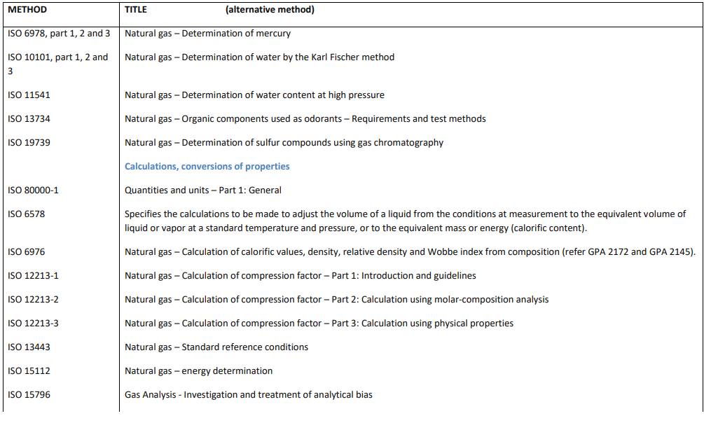
International standards exist for the classical methods and techniques used for LNG Custody Transfer such as ISO 6976 for calculation of the GCV of gas.
On the other hand, a number of existing LNG supply, shipping and purchase agreements specify GPA 2261 for gas chromatography and HM 21 or GPA 2145 and GPA 2172 for the calculation of the GCV of the gas. Buyer and Seller may approve one of these editions, usually the most recent edition.
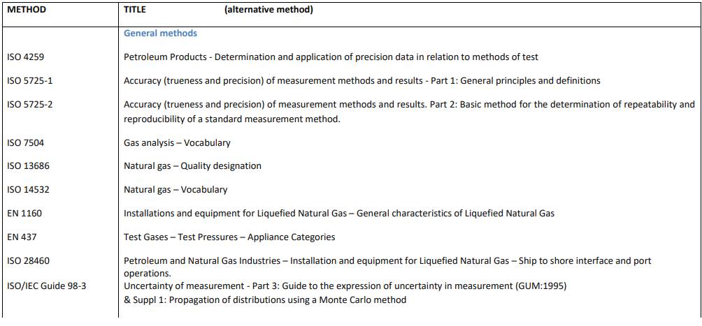
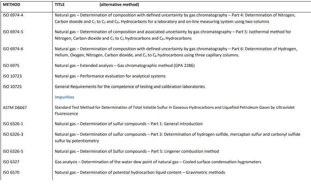
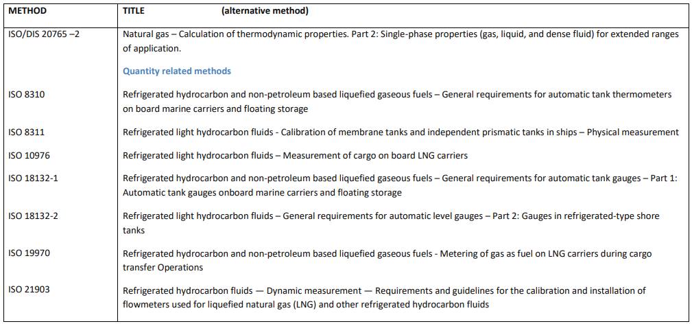
As far as methods and techniques dealing with static measurement procedures for LNG are concerned, it should be noted that ISO has issued numerous international standards, (see below).
LNG AND NATURAL GAS CUSTODY TRANSFER METHODS
ISO standard methods, being the highest level of international methods, are to be recommended. Equivalent alternatives, as indicated, from other institutes, like GPA, IP or ASTM can also be used, and may be agreed between all parties involved. It is however recommended to consistently and coherently use either ISO or GPA references or other consistent contractual requirements. In other words, a mix of ISO, GPA and/or other reference documents should be avoided.
These methods are regularly updated, and readers are strongly advised to check that they are in possession of the latest issues.

The recommendations included in these documents and future international standards are appropriate to be considered for new agreements.
Partial loading or unloading of LNG carriers
In recent years there has been a worldwide increase in short term and spot cargo LNG trading, involving two new operating trends in LNG shipping:
- more and more LNG shippers are using LNG carriers as floating LNG storage;
- several LNG shippers have considered, and some have carried out, partial unloading and/or partial loading of one or several cargo tanks of LNG carriers.
When performing such operations, due attention should be given to:
- safe ship/shore operating practices and procedures;
- proper LNG ship/shore custody transfer procedures.
Please refer below for recommended safe practices for partial (un)loading.
SOME RECOMMENDATIONS FOR PARTIAL RELOADING OF CARGO TANKS OF LNG CARRIERS, WITH REGARD TO BOTH SAFETY AND CUSTODY TRANSFER ISSUES
For information only
Introduction and context
In the last decade we have seen a worldwide development of short term and spot cargo LNG trade, involving two new operating trends in LNG shipping:
- LNG shippers are using LNG carriers for spot cargoes and/or as floating LNG storage;
- several LNG Shippers have considered, and some have carried out, partial unloading and/or partial reloading, i. e., unloading or reloading only one or some of the cargo tanks of the LNG carrier.
When performing such operations, due attention should be given to:
- safe ship/shore operating practices and procedures, and;
- proper LNG ship/shore custody transfer procedures.
One of the considerations for safe operating practices and procedures should be to prevent the creation of stratified layers and the risk of a subsequent rollover in the cargo tank(s) involved. Stratification and rollover could occur either when the LNG carrier is alongside the berth of an LNG terminal or alongside another LNG carrier undergoing a partial reloading operation, when at sea, or when unloading its partially loaded LNG cargo in another LNG carrier or at another LNG terminal. In the last case, the risk of stratified layers and subsequent rollover is in the receiving LNG terminal’s shore tanks.
Custody Transfer recommendations when considering the reloading of LNG carriers for «partial reloading» operations
Stratified layers in cargo tanks of LNG carriers can (and have) subsequently resulted in rollover either in the cargo tanks of the LNG carrier or in the receiving on-shore LNG tanks (see below).
TWO CASE STUDIES ILLUSTRATING POTENTIAL RISKS OF STRATIFICATION AND ROLLOVER IN LNG SHIP’S CARGO TANKS
Density-stratified liquid layers in LNG cargo tanks upon arrival at importing terminal
The table below shows a comparison of the LNG temperatures over the height of 5 cargo tanks recorded at the closing CTS at the export terminal with those recorded at the opening CTS at the import terminal, and the temperature difference between both.
- CT – Cargo tank No.
- DEP – Closing Custody Transfer Survey upon DEParture at the export terminal.
- ARR – Opening Custody Transfer Survey upon Arrival at the import terminal.
- ΔT – temperature difference.
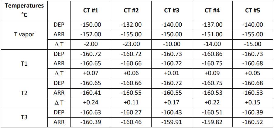
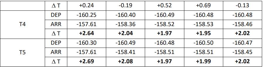
From this table, and especially the figures in bold, it can be seen that between the closing custody transfer survey upon loading and the opening custody transfer survey before unloading, substantial shifts in liquid temperature occurred onboard the LNG carrier, indicating stratification in these cargo tanks.
Sequence of events:
- During loading pumping was switched from an LNG shore tank with lower density to one with much higher density (Density difference: 20 kg/m3).
- Since the cargo tanks have bottom fill only, a stable denser bottom layer was induced during loading.
- This layer warmed up during the loaded voyage.
- Because of the substantial density difference, warming up by up to 2,69 °C did not induce a sufficient density decrease to destabilize the bottom layer: even after this substantial temperature increase, its density was still higher than that of the upper layer.
- As this bottom layer was the first one to be pumped out on unloading, immediate extensive flashing in the shore tanks occurred, causing a sharp pressure increase resulting in the opening of a shore tank safety relief valve.
- The number of running cargo tank pumps had to be reduced from 6 at the time of the relief valve opening to 4. Even then the large unloading compressor (30 ton/h BOG) had to be started, instead of the usual two BOG compressors at 4 ton/h each.
- As soon as the discontinuous LNG analysis indicated that the lighter layer started to come through, the shore tank pressure decreased and the large unloading compressor could be stopped, and the number of running cargo pumps could be increased to the normal 10.
- Analysis of the LNG composition combined with the unloading flow indicated that the cargo had consisted of about 30 % high density LNG, 20 % intermediate mixture and 50 % lighter density.
- About 58 tons of flash gas had to be flared.
Lessons learned:
- If the crew of a loaded LNG carrier detects density stratified layers on board on its way to a receiving LNG terminal, the master should notify the receiving terminal and propose a special pre-discharge meeting on board focusing on this issue. At this meeting ship and shore should agree how to take appropriate precautions in concert.
- How to detect stratified layers on board an LNG carrier that did not notify the receiving terminal in advance? Make sure that for the opening CTS you always have the Bill of Lading at hand to compare the temperature profile in each cargo tank and the tank pressure with those upon departure at the loading terminal. If you detect any abnormality such as shown in the above table, then immediately notify the master or cargo officer of this and develop an appropriate unloading strategy in concert with the ship. For instance, start unloading at an intentionally reduced rate, e. g. with 4 pumps only. Check that the vapor return rate from the ship is not excessive. If not, then you can gradually increase the unloading rate by running more LNG transfer pumps on board ship.
- Calculate the SVP (= saturated vapor pressure, calculated based on the LNG composition at loading and current LNG liquid temperatures upon arrival at the unloading terminal), and compare this SVP with the actual tank pressure in the ship’s cargo tanks.
- If the SVP is substantially higher (e. g. more than 20 mbar or 2 kPa) than the actual tank pressure in the ship’s cargo tanks, then expect excessive flash gas upon unloading and act very prudently especially at the beginning of the unloading operation. As a guidance, a rule of thumb is that for every 0,1 °C temperature increase of a given LNG batch, the saturated vapor pressure increases by approx. 10 mbar ±3 mbar (i. e. 7 … 13 mbar).
- Stratification and rollover in one or more ship’s cargo tanks are detrimental for a proper and accurate custody transfer upon unloading.
- When loading LNG cargo tanks check that the LNG batch designated to be loaded is as homogeneous as possible. As a guide it is proposed that LNG density differences be less than 1 kg/m3, temperature differences less than 0,5 °C, differences in saturated vapor pressure less than 10 mbar and the LNG composition as similar as possible.
Density-stratified liquid layers in LNG cargo tanks upon departure at exporting terminal
The table below shows a comparison of the LNG temperatures over the height of 5 cargo tanks recorded at the closing CTS at the export terminal with those recorded at the opening CTS at the import terminal, and the temperature difference between both.
- CT – Cargo tank No.
- DEP – Closing Custody Transfer Survey before Departure at the export terminal.
- ARR – Opening Custody Transfer Survey upon Arrival at the import terminal.
- ΔT – temperature difference.

From this table it can be seen that between the closing custody transfer survey upon loading and the opening custody transfer survey before unloading, substantial shifts in both vapor and liquid temperature occurred in cargo tanks #3 and #4, indicating stratification in these cargo tanks.
Sequence of events:
- Previous LNG cargo: LNG cargo with lighter density.
- Approx. 8 500 m3 LNG was retained onboard as heel in CT#3 and CT#4 in view of a 7-week voyage to the loading terminal.
- After 2-weeks voyage, vessel was assigned to load at a receiving LNG terminal instead. Upon arrival there was still approximately 5 400 m3 heel onboard.
- Loading operation at receiving terminal: loading rate was max. 4 200 m3/h instead of the usual 11 000 m3/h at export terminals (bottleneck: terminal loading pump capacity).
- Equator temperature in ship’s spherical cargo tanks must be < -134 °C when the liquid level reaches 1 meter below the equator level. The vessel would normally conduct spraying operations during loading in order to meet this requirement.
- The terminal vapor system could not accept mist (droplets) in the vapor returned from the vessel. Therefore the vessel was not able to conduct spraying operations during the loading.
- The vessel stopped loading each tank for 2-7 hours at 1 meter below the equator level to ensure that the equator was cooled to below –134 °C.
- The above factors may have contributed to the formation of density-stratified liquid layers in the heel tanks.
- On completion of loading there was a big differential between temperature sensor T2 (located at 85 % of tank height) and T3 & T4 (located at 50 % of tank height = equator, and cargo tank bottom respectively).
- Loaded voyage to unloading port: 5-7 Beaufort, swell 1-2 meters, very little rolling or vibration, low voyage speed approximately 12 knots.
- Increase in liquid levels noted in cargo tanks #3 and #4.
- Liquid level in CT #3 increased until one day after loaded departure.
- Liquid level in CT #4 increased until three days after loaded departure.
- Once rollover occurred the liquid level went down rapidly.
- Liquid level became steady when the circumstances (temperature, pressure) in the tank had stabilised.
- Vapor temperature cooled after the liquid level came down in CT #3, which indicates the generation of significant more BOG.
- 5 days after loaded departure, rollover occurred in cargo tank #3: upper and lower liquid temperature rapidly changed (within some 5 hours): upper liquid temperature T2 increased, lower liquid temperatures T3 & T4 decreased, temperature in vapor dome dropped by 6 °C in some 5 hours.
- 6 days after loaded departure and 1 day after rollover in cargo tank # 3, the crew started spray pump in cargo tank #4 to encourage intentional rollover under controlled conditions: spraying was stopped when tank pressure reached 18 kPa (180 mbarg).
- 7 days after loaded departure rollover occurred in cargo tank #4 about 1 hour after encouraging it:
- again the upper liquid temperature T2 rose rapidly while the lower liquid temperatures T3 & T4 dropped rapidly by more than 1 °C within approximately one hour, i. e. much faster than during the spontaneous rollover in cargo tank #3;
- during this rollover in cargo tank #4, the vapor temperature in the tank dome (T1) dropped by more than 11 °C.
- Cargo tank pressure in cargo tank #3: during rollover in CT #3 tank pressure rose from 11,5 kPa to 16,5 kPa, whereas during rollover in CT #4 the next day tank pressure in CT #3 even rose from 11,5 kPa to 20 kPa.
- When the crew detected that rollover had occurred in cargo tanks #3 and #4, all vapor suction valves except those of cargo tanks #3 and #4 were closed down to the minimum open position necessary and sufficient to maintain safe tank pressures in cargo tanks #1, #2 and #5, in order to remove as much BOG as possible from the rollover cargo tanks #3 and #4.
- On berthing at the unloading terminal, the liquid temperatures and the tank pressures were not yet at a safe level to conduct the opening CTS and the ESD trip tests. So the master of the vessel coordinated with the terminal to send excess BOG from ship to shore flare, to reach a stable condition as soon as possible.
Lessons learned:
These two rollover events in CT #3 and CT #4 were rather mild rollovers: the cargotank pressures were maintained within design parameters at all times. However, the incident demonstrated that:
- Although it was previously believed by many that rollover would be unlikely to occur in a Moss-Rosenberg type cargo tank, because the spherical shape of the tank would aid the migration of the warmed liquid along the tank wall, clearly, it did not do so sufficiently in this case.
- Stratification and rollover conditions can develop on board ship particularly when (bottom) (re)loading a higher density LNG into a tank containing a heel or cargo with lighter density.
- Ship movement on passage cannot be relied upon to mix layers of different density.
- An increase of the liquid level in one or more cargo tanks may be an indication of stratification. The shape of spherical cargo tanks act as a «magnifying lens» for readily noting changes in volume.
- Reduction in boil-off gas generation may indicate stratification.
- Stratification and rollover in one or more ship’s cargo tanks are detrimental for a proper and accurate custody transfer upon unloading.
Recommendations for a proper custody transfer when partial reloading:
- Avoid filling a cargo tank with a heel of more than 1 m heel height.
- If due to practical circumstances a heel of more than 1 m cannot be avoided, then the following is recommended. Check that the physical properties of the LNG cargo to be reloaded are as close as possible to those of the heel in the cargo tank, e. g. LNG density difference less than 1 kg/m3 and preferably lower than the density of the heel, temperature difference not more than 0,5 °C, difference in saturated vapor pressure not more than 30 mbar.
It should be noted that at the time of writing there is still limited knowledge, reporting and field experience regarding stratification and rollover issues in cargo tanks of LNG carriers. Persistent suggestions that ship movements and sloshing of the LNG cargo would always ensure complete mixing of any stratified layers have been disproved by a few reported cases of stratification and even rollover in cargo tanks of LNG carriers. Therefore, all parties acting as prudent and reasonable operators both off-shore and on-shore, should adhere to the following guidelines, particularly with regards to partial loading of cargo tanks.
In view of the above, it should be strongly recommended to first unload a partially filled cargo tank (i. e., a cargo tank filled with more than a minimal heel of only a few % of cargo tank height), and then to reload it with a fresh cargo of LNG.
If an LNG carrier, typically in a spot cargo situation, arrives at an LNG terminal with one or several cargo tanks filled and others empty (perhaps except for a minimal heel), with the intention to load the remaining cargo tanks as well, then prior to agreeing to the LNG carrier’s call at that LNG terminal for such a partial reloading operation, the LNG Shipper shall provide the LNG Terminal Operator with an appropriate cargo tank management procedure for such partial reloading of the LNG carrier, thereby ensuring that the following rules for proper custody transfer are strictly adhered to.
Here are a few proposed items for such a procedure.
A Filling an LNG cargo tank with a heel height exceeding 5 % of max. cargo tank filling height shall not be allowed.
B Likewise, topping up a cargo with LNG transferred from an LNG Terminal tank shall not be allowed. Therefore, before starting a partial loading operation for one or several of the ship’s cargo tanks, if necessary each cargo tank in either of the above-mentioned conditions shall first be emptied to the recommended minimum heel level, typically only 0,5 or 1 m of liquid level. Parties should agree on the limits in LNG temperature difference and LNG density difference between the heel and the LNG cargo to be loaded – as default values a maximum acceptable difference of 1 °C and 1 kg/m3 respectively between this minimal heel and the loaded cargo are proposed.
C If an LNG Shipper proposes to call at an LNG terminal with an LNG carrier with one or several cargo tanks full and the others empty (or with a minimum heel), and wishes to reload only the empty cargo tanks, then the following strict guidelines are recommended, to ensure a proper custody transfer both on departure and arrival.
- First of all the Shipper should demonstrate in full detail and in writing that he is able to determine with an overall uncertainty better than 1 % (see Recommended methods for calculating LNG“Uncertainty of the energy transfer determination”) the relevant physical properties of the LNG cargo that is on board the LNG carrier.
- Assuming that the LNG Shipper is able to demonstrate the above, then the parties should verify, based on well-established and proven methods, that there is sufficient compatibility between the physical properties of, on the one hand, the LNG cargo onboard in certain cargo tanks, and on the other hand the LNG batch from LNG shore tanks that is to be loaded in the other cargo tanks. As a guidance the following criteria are recommended:
- Max. 1 kg/m3 difference in LNG density between the LNG parcels in the ship’s cargo tanks.
- Max. 0,5 °C difference in average liquid temperature between the ship’s cargo tanks.
- Max. 50 mbar difference in saturated vapor pressure between the LNG parcels in the ship’s cargo tanks. The saturated vapor pressure in each cargo tank shall be calculated with the same method.
- If these criteria cannot be met, then the LNG Shipper should refrain from such a partial reloading operation and first unload all LNG onboard, and next load a fresh and homogeneous cargo of LNG from the shore terminal.
- Likewise, if the LNG batch that is to be reloaded from more than one LNG shore tank, as a guidance the following criteria for these LNG shore tanks are recommended:
- Max. 1,0 kg/m3 difference in LNG density between the LNG shore tanks.
- Max. 0,5 °C difference in average liquid temperature between the LNG shore tanks.
- Max. 50 mbar difference in saturated vapor pressure between the LNG shore tanks; The saturated vapor pressure in each shore tank shall be calculated with the same method.
- One of the purposes of these recommendations is to ensure an accurate custody transfer on unloading, since even small differences in liquid temperature of only a few tenths of a °C between cargo tanks have a detrimental influence on the combined standard uncertainty and overall uncertainty of the calculated energy transferred (see Section 4.1.2* and Recommended methods for calculating LNG“Uncertainty of the energy transfer determination”).
As mentioned in section 2.3.1*, it is usual to retain a quantity of LNG («heel») on board after unloading to keep LNG tanks cold during the journey to the next loading port.
However, in some cases, the LNG vessel may retain a larger heel on board after unloading or only unload a partial cargo, which could have the following consequences:
a Sloshing:
Depending on the characteristics of the LNG vessel and the heel level, it may cause a risk of sloshing. In accordance with the operational rules of the LNG vessel, this can be managed by keeping the heel in one LNG tank or distributing it among different LNG tanks of the LNG vessel.
b Impact on the next loading of the LNG vessel:
If the LNG vessel loads a cargo of the same quality as the heel, the two LNGs can be mixed, e. g., in case of a loading at the same loading port as previous loading, there should not be a significant difference between LNG loaded and the heel present (except for the possible impact of aging).
If the LNG vessel loads LNG with a significantly different quality to the heel, it may be better not to mix them if the safe operational result of blending the different qualities is not guaranteed, e.g it may be possible to keep the two qualities in different LNG tanks of the LNG vessel, to avoid any incidents in the operation of the LNG vessel.
c In the case of two different qualities on board of the LNG vessel, the impact on the next unloading:
Discharge the two different qualities consecutively. This implies separate unloading operations and related custody transfer procedures for each LNG quality. The time for unloading may therefore be longer than usual.
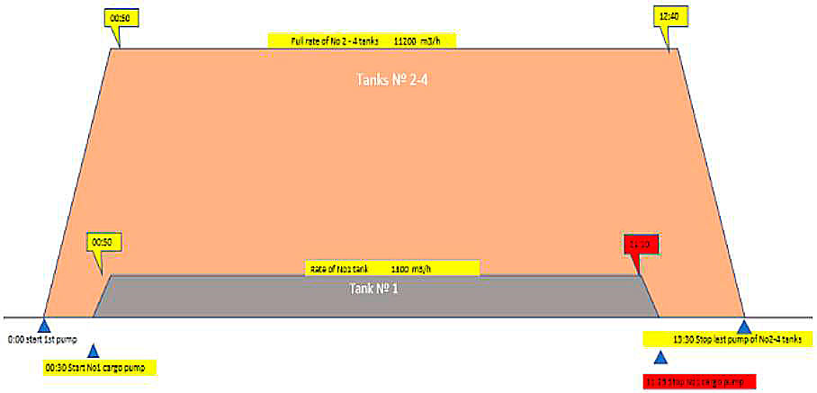
Discharge the two different qualities simultaneously. In this case, the smaller LNG volume (heel retained) should be discharged at a lower speed, so its discharge time matches the discharge time of the larger LNG volume thereby mixing the different LNG qualities as uniformly as possible (see figure).
In both cases, the Terminal Operator must authorize the option applied.
d The unloading Terminal can request two Bill of Loadings (BoL) corresponding with the two different qualities loaded in the previous ports.
Gassing-up and cooling down operations
Gassing-up operations. When an LNG vessel is delivered or after dry dock, the cargo tanks are often filled with inert (exhaust) gas. As inert exhaust gas contains carbon dioxide which will freeze during loading, it must be replaced with warm LNG vapor prior to cooling down the tanks in preparation of loading.
This process is called gassing-up and is normally preceded by a process of drying and inerting.
Drying can be done with hot air (or nitrogen) and inerting is performed to remove the oxygen out of the cargo tanks and replace the air/oxygen by inert gases (exhaust gases of the ship or nitrogen). In case drying and inerting are performed with nitrogen, both steps can be combined in one operation. The reason behind the preliminary operations of drying and inerting is not to directly replace air by natural gas due to safety reasons (hence avoiding an explosive atmosphere during the operation).
Once inerted, the shore will supply LNG which is sent to the main vaporizer of the ship to produce vapor warmer than the dew point temperature in the cargo tank. This vapor is then injected at the top of the cargo tank to displace the inert gas. The increase of pressure and the difference in density forces the inert gases out of the cargo tanks. The exhaust gas is generally directed to the ship’s (forward) vent mast, to a vent on shore or burnt in the terminal’s flare (at the beginning it is fully inert and gradually becomes a mixture of nitrogen and inert gases (which percentage is decreasing) and natural gas (which percentage is increasing). This process continues until the exhaust gas is measured to have approx. 98-99 % of methane and the CO2-content is less than a certain low threshold (e. g., 0,1 %). Once this is accomplished, the vessel is ready to receive cold vapor and start the cooling down process.
The quantity of LNG required for this operation depends on the size and construction of the vessel’s cargo tanks. The gas quality considered for gassing up is usually the same as the quality for cooling and for loading, but some loading/reloading facilities can use different gas qualities for each operation. The energy required for gassing-up the cargo tanks is stated in the terminal rules or in the contract between the parties, but the most commonly used technique is to use the certified gassing-up tables of the LNG vessel.
The certified gassing-up tables apply a volume of natural gas which is between 1,7 and 2 times (each LNG vessel has a coefficient) the volume of each cargo tank, which is the theoretical volume of gas to be supplied to each cargo tank for the purpose of gassing-up this cargo tank.
Each vessel will have a gassing-up table for each tank on board. These are provided by the Liquefied Natural Gas Tank Protectiontank manufacturer and confirmed by an independent surveyor during construction at the shipyard. Each table is designed specifically for that particular type of containment system. For example, a 145 000 m3 size membrane vessel will require approx. 420 m3 of LNG or 2 850 MWh for a complete gassing-up operation. This gassing-up operation will take approx. 20 hours to complete depending upon the LNG supply and the vaporization rate on the vessel. The gassing-up tables should be reviewed and agreed upon by all parties at the preliminary meeting prior to commencing any operations.
There are some terminals which correct the theoretical volume taking into account the measurement conditions when these are different than the ones in the certified gassing-up tables.
Read also: Usage of Natural Gas Compressors in the Gas Production Operations
Other alternatives to measure the energy for gassing-up (especially for old LNG vessels which do not have certified gassing-up tables) are the following ones:
- a) the procedure stated in the LNG vessel Operations Manual;
- b) to apply twice the theoretical volume of each cargo tank to obtain the theoretical energy for gassing up;
- c) to measure the delivered LNG (in cubic meters) during the gassing-up operation by means of an LNG mass or flow meter;
- d) to measure the difference in level in the shore LNG tanks. In this case, it is necessary to take into account any other filling (e. g., cold circulation) or emptying (e. g., send out for regasification purposes) operations of the tanks.
Cooling down operations
Cooling down operations are performed to slowly reduce the temperature of the cargo tanks close to that of the LNG to be loaded in order to avoid any structural damages by thermal shock or stress to the tank construction. The target is to reach a certain reference temperature according to the performance criteria stated in the operations manual or cool down tables of the LNG vessel.
Cooling down operations are generally performed on an LNG ship of which the cargo tanks are under (warm) natural gas (e. g., after a long ballast voyage during which the cargo tanks have been warmed up or (immediately) after gassing-up operations). However, it is also possible to cool down an LNG ship of which the cargo tanks have been fully dried and inerted with nitrogen, hence avoiding gassing-up operations.
LNG is supplied by the LNG terminal and it is vaporized and injected at a controlled rate into the ship’s cargo tanks through spray nozzles at the top of the cargo tanks to avoid thermal shock in the tanks and its devices (such as pumps, pump columns, probes…). Once the LNG is vaporized, there is an increase of pressure in the cargo tanks and the gas return is sent to the terminal’s vapor return system or to the terminal’s flare to keep the pressure in the cargo tanks under control. The LNG vessel can also help reducing its cargo tank pressure by burning gas as fuel (in the engines or in the gas combustion unit).
The required temperature needed before loading can be started is identified in the Operations Manual or the cool down tables provided by the tank manufacturer. Each cool down table is specific to that tank type, is issued by the manufacturer during construction and is verified by an independent surveyor prior to the vessel being delivered. The cool down tables identify the quantity and length of time required to complete the operation prior to loading. The gas quality considered for cooling down is usually the same than the quality for loading (and gassing-up if there is any), but some loading/reloading facilities can consider different gas qualities for each operation. The energy required for the cooling down operations of the cargo tanks is stated in the terminal rules or in the contract between the parties, but it is usual to apply the use of the cool down tables or one of the following alternatives. Cooling down tables.
The most common method is the use of the cool down tables. Based on the size of the cargo tank, the manufacturer calculates how many cubic meters of LNG or what energy content are required to lower the temperature inside the tank one degree Celsius. Then based on the vapor temperature inside the tank at the beginning of the operation, the quantity is calculated accordingly. The time it takes to complete a cooling down operation depends on the temperature prior to starting the operation. The cooling down tables should be reviewed and agreed upon by all parties at the preliminary meeting prior to commencing any operation.
Cooling down operations are generally faster than gassing-up operations. It takes approx. 10 to 12 hours for a membrane type LNG vessel and approx. 20 hours for a Moss type vessel.
- a) Membrane type LNG vessels.
In this type of vessel, the reference temperature is the average temperature (vapor phase) of the pump tower in each tank excluding the first top or two top sensors (depending on terminal rules/contract between the parties).
The reference temperature for loading a membrane type LNG vessel shall be approximately -130 °C.
It is usual to use the certified cooling down tables. These tables give the energy required to cool down each tank from its arrival temperature to -130 °C.
The certified cooling down tables have been made up supposing a certain gas type in order to obtain the energy. Once cooling down energy has been obtained, it is possible to obtain an LNG cubic meter equivalent for this cooling down operation.
The tables are divided into two sections:
- warm conditions. These are used in case the average temperature in the cargo tanks is higher than -40 °C. The table normally spans the range between +40 °C and -130 °C. In this case the operation can take about 10 to 12 hours;
- cold conditions. These are used in case the average temperature in the cargo tanks is equal to or lower than -40 °C. The table normally spans the range between -40 °C and -130 °C. In this case the operation can take about 6 to 8 hours.
- b) Moss type LNG vessels.
In this type of vessel, the temperature reference is the equatorial temperature of the cargo tanks. The reference temperature for loading a Moss type LNG vessel normally spans the range between -110 °C and -130 °C depending on the operations manual of the LNG vessel.
In this case, the certified cooling down tables could give:
- the LNG volume needed to reduce the equator temperature of the tank by one degree Celsius. The total LNG quantity required for cooling down the cargo tanks will be calculated by multiplying the difference between the initial equator temperature and temperature reference by the value of cubic meters that are needed to lower the equator temperature by one degree Celsius;
- the LNG volume and energy needed to reach the reference temperature (as the equatorial temperature).
Nozzle pressure. The cooling down operations are performed by injecting LNG through special spray nozzles into the cargo tanks. The flow is fully dependent on the applied pressure. The number of nozzles, the average pressure, and the duration of the spraying for each tank can be used to determine the volume of LNG used for the cooling down operations.
In case the cooling down operations are performed on an LNG ship of which the cargo tanks are under nitrogen, the cool down tables may be used as well, however this should be agreed upon by all parties.