LNG samples and temperature measurements are carried out to ensure the quality and characteristics of liquefied natural gas. All of this is critical because LNG needs to be stored at very low temperatures to keep it in a liquid state.
- Temperature measurement
- Liquid temperature
- Vapor temperature
- Vapor pressure
- Sampling of LNG
- LNG Sampling principles
- Sampling point
- Sampling probes
- Piping arrangement between sampling probe and vaporizer
- LNG vaporizer and control devices
- Gas sample conditioning
- Performance of the devices
- Sampling procedure
- Spot sampling device
Proper sampling techniques and accurate temperature monitoring help ensure safe LNG transportation and delivery.
Temperature measurement
Liquid temperature
Device
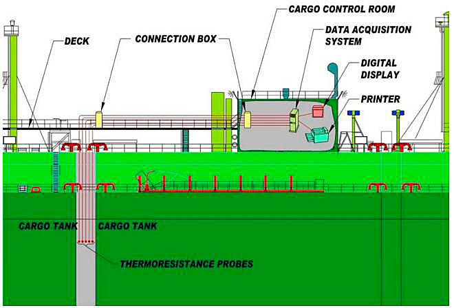
The LNG temperature is measured by probes placed at different heights in the tanks. These probes are generally three- or four-wire platinum resistance temperature sensors (usually PT100), of which there are typically five per cargo tank. Recently built LNG ships often have also calibrated back-up sensors fitted next to each main thermal sensor, which can be selected and used in case of main sensor failure.
One probe should always be in the liquid phase at the bottom of the tank and one always in the vapor phase at the top of the tank.
The tank gauge table also provides the vertical height of the location of the temperature sensors, so that it may be determined whether the sensor is in the liquid or in the vapor phase during custody transfer measurement.
The temperature measurement of these probes is converted into degrees Celsius with the help of a data acquisition computer equipped with a printer. Table 1 shows an example of a printout of LNG temperatures when the tanks are filled to 98 % capacity with LNG.
| Example of tank temperature recordings (98 % Filled) | |||||
|---|---|---|---|---|---|
| TEMPERATURE PROBE | TANK 1 °C | TANK 2 °C | TANK 3 °C | TANK 4 °C | TANK 5 °C |
| T 1 | -161,83 | -161,90 | -161,94 | -161,89 | -161,84 |
| T 2 | -161,80 | -161,88 | -161,91 | -161,89 | -161,86 |
| T 3 | -161,82 | -161,87 | -161,92 | -161,90 | -161,90 |
| T 4 | -161,79 | -161,86 | -161,87 | -161,88 | -161,81 |
| T 5 | -161,82 | -161,82 | -161,88 | -161,91 | -161,84 |
| TANK AVERAGE | -161,81 | -161,87 | -161,90 | -161,89 | -161,85 |
| The liquid temperature in each tank is determined by the arithmetic average of temperatures indicated by the probes that are dipped in the LNG and that are in working order. | |||||
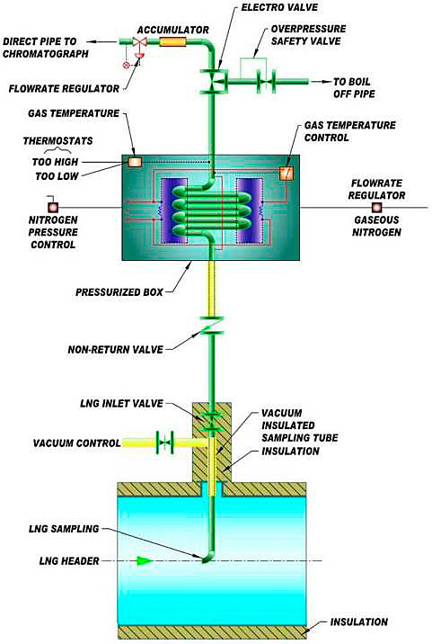
Figure 1 shows a diagram of temperature measuring devices installed on a LNG carrier. In this example, five probes are immersed in LNG in each tank. A sixth probe (not shown) is in the vapor phase at the top of the tank.
The average liquid temperature is calculated upon the opening and the closing Custody Transfer Surveys. The average liquid temperature is calculated using the temperature reading at each individual temperature sensor that is in the liquid, and not the average temperature of each cargo tank.
Thermocouples are not used for LNG temperature measurement within custody transfer because they are less sensitive at very low temperatures and often give a less accurate measurement than platinum resistance probes. In addition, their installation is more complex requiring compensation cables. They may be installed sometimes for control or simple indication purposes such as cooling down or heating of the tank.
Testing and accuracy
The accuracy of the platinum resistance thermometer varies between ±0,1 and ±0,2 °C for temperatures ranging between -145 and -165 °C. The overall uncertainty of the temperature measuring chain can be estimated at about ±0,5 °C (including sensor, cable, signal converter, display).
The sensors are tested for accuracy at the manufacturer’s facility prior to installation, and certified/calibrated upon installation in the cargo tanks. The temperature measurement is tested and recalibrated at regular intervals to ensure continued performance.
The influence of temperature measurement accuracies on the determination of LNG density (see Recommended methods for calculating LNG“Uncertainty of the energy transfer determination”) is important. For instance, for LNG with an average density in the range 440-470 kg/m3, and at a temperature around -162 °C, the relative accuracy in density calculation, due to an accuracy of 0,5 °C in temperature measurement, is about 0,15 %.
Vapor temperature
The temperature in the gaseous phase of the tanks is used to determine the quantity of gas displaced during the loading and unloading operations, or the level correction of the float gauge due to ribbon shrinkage.
As for liquid temperatures, the average vapor temperature is calculated using the temperature reading at each individual temperature sensor, and not the average temperature of each cargo tank. However, only temperatures indicated by probes not immersed in the LNG are averaged in this case.
Typically, an accuracy of ±1,0 °C (in the range -145 to +40 °C) is required.
Vapor pressure
Vapor pressure measurements can be made with a pressure gauge, which indicates the pressure in the gas spaces of the cargo tanks.
This pressure is needed to calculate the energy of displaced gas, see Recommended methods for calculating LNG“Energy of gas displaced from the LNG tanks”. For this, it is necessary for the pressure to be in absolute terms. If the ship’s instrumentation measures pressure in “gauge” terms, then the atmospheric pressure must be recorded and added to the gauge pressure.
The pressure value is recorded, with the atmospheric pressure if appropriate, at the time of taking the other CTS readings.
Typically, the required pressure measurement accuracy is specified as between ±0,1 and 1 % FS (% of full-scale instrument range).
ISO 10976 also addresses vapor pressure measurement.
Sampling of LNG
LNG Sampling principles
In order to determine the quality of the LNG it is first necessary to undertake particular operations to condition the fluid sampled from its initial state, liquid at low temperature, to a final state, gas at ambient temperature, without partial vaporization or loss of product.
Sampling of LNG includes three successive operations:
- taking a representative sample of LNG;
- complete and instant vaporization;
- conditioning the gaseous sample (e. g., ensuring constant temperature and pressure) before transporting it to the analyzer and/or sampler.
Sampling is the most critical point of the LNG measurements chain. Each step must be taken without changing the sample composition. This is by far the most complicated step of the measurements and most of the problems observed in determination of the energy loaded or unloaded come from the sampling system. The sampling system is not changeable during unloading/loading. Some operators have a back-up sampling system to ensure sample collection in the event of failure of the main system.
The LNG industry has evolved the sampling processes. The «spot (discontinuous) sampling system» described in the first edition of this handbook has become almost obsolete for CTS measurements. It is therefore recommended to use this only as a back-up system in case of failure of the main device. The spot sampling system may be used, however, for the (manual) sampling for impurity analyses. For completeness, description of this system is given below.
The sampling processes currently used in the LNG industry are mainly of two types; continuous sampling and intermittent sampling, both sampling processes as defined in ISO 8943. The intermittent sampling is also referred to as discontinuous sampling in other publications such as the EN 12838 standard and the current GIIGNL handbook. Please note that the terminology continuous/discontinuous is different from that used in the first and second edition of this handbook.
The terms continuous and discontinuous sampling are related to the analysis of gaseous LNG, that is, after evaporation of the sampled liquid stream. LNG sampling systems always sample LNG on a continuous basis:
- continuous sampling.
This sampling process involves continuous collection of LNG from the LNG flow line during the loading/unloading operations. The regasified LNG from the vaporizer is thereafter continuously fed into the gas sample holder. Gas sample containers (definition according to ISO 8943) are filled with the mixed gas from this gasholder after completion of the sampling process for offline analysis.
- discontinuous sampling (referred to as intermittent by ISO 8943).
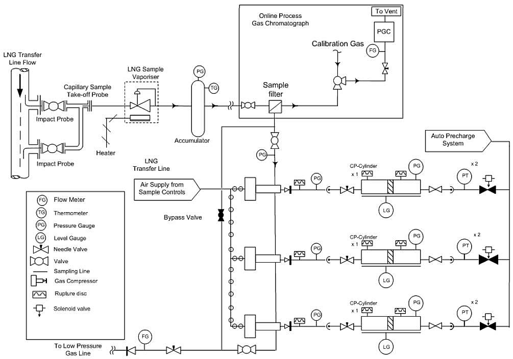
This sampling process also involves continuous collection of LNG from the LNG flow line during loading/unloading operations. However, the regasified LNG from the vaporizer is in this process partly directed to an on-line GC and partly into a constant pressure floating piston (CP/FP) sample container (definition according to ISO 8943). A CP/FP sample container is capable of maintaining constant pressure during the sampling of gas from the process line into the gas cylinder. The gas sample collected in the CP/FP sample container is for offline analysis.
European Standard EN 12838 specifies tests to be carried out in order to assess the suitability of these two LNG sampling systems. However, this EN standard was published before the current version of ISO 8943 and actually refers to the previous version of this ISO standard. The most important difference is that the discontinuous process described in the EN 12838 standard is replaced by the intermittent process in ISO 8943. The discontinuous method directs all sample gas to the on-line GC while the intermittent process in addition includes a method to fill sample CP/FP containers. This allows for retained sample analysis.
Current LNG sampling systems in operation deviates from those in the standard and cause confusion whether the system can be described as continuous or discontinuous.
The LNG sampling devices shall be such as to ensure the total and continuous vaporization of a quantity of LNG. This quantity must be sufficient for taking gaseous samples representative of the LNG being (un)loaded.
Most Ship/shore interface for safe loading and unloading of LNG/LPGLNG terminal ship unloading lines (and LNG production plant loading lines) have two main operating modes:
- circulation of LNG from the storage tanks when there are no (un)loading operations;
- LNG Carrier (un)loading.
The operating pressure can be quite different in each operating mode.
The sampling system should preferably be designed in such way to assure representative vaporization even during the lowest LNG line pressure. Sub- cooling (see ISO 8943, annex A) of LNG up to the vaporizer should be ensured at all times when the system is used for heating value determination of the LNG. This could require vent gas flow adjustment between changes in operating mode or vaporizer setting adjustments (temperature, power). Lowering the static pressure should be carried out very prudently to avoid adverse (e. g., geysering) effects in these long lines.
Sampling point
The sampling point is generally located:
- on the main loading pipe (line), after the LNG pumps send-out;
- on the main unloading pipe (line), after the unloading arms.
LNG must be sampled during a stable flow of LNG. It is preferable to install the sampling point as close as possible to the custody transfer point (loading arm flange/ship manifold or main header) so that the characteristics of LNG do not change before it is actually transferred because of potential heat input. However, generally the influence of heat input is limited, when the flow does not vary too much in the properly insulated main unloading/loading line.
Again, please note that the LNG must arrive in a sub-cooled condition at the sampling point/vaporizer. The LNG sub-cooled condition can be determined by using the method proposed in ISO 8943 (annex A). If this is not ensured representative sampling is likely to fail.
Sampling probes
In order to keep the LNG sampling flow in a sub- cooled condition, the ambient heat input should be minimised. The following layouts can be used:
- a straight sampling tube inside the main LNG header (Figure 2, a);
- a direct connection on the periphery of the main LNG header by appropriate insulation around the sampling tube to reduce the ambient heat input to the main pipe (Figure 2, b).
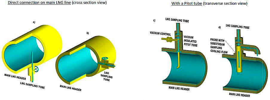
Remark: both above lay-outs require appropriate insulation around the sampling tube, sample stream can be further minimised by an (optional) permanent external side-stream LNG flow to a purge line of the plant.
Improved sampling systems use Pitot tubes. They can have:
- vacuum insulation around the Pitot sampling tube (Figure 2, c) completed with appropriate insulation of the top part of the probe;
- an LNG Pitot sampling tube cooled by a permanent internal side stream flow initiated with natural LNG circulation going back to the LNG header (Figure 2, d).
Piping arrangement between sampling probe and vaporizer
It is important to have the liquid sample line, between the sampling probe and the Use of Vaporisers on Liquefied Natural Gas CarriersLNG vaporizer, as short as possible, with a small inside diameter (1 or 2 mm for instance) and with sufficient insulation, so that the LNG is kept in a sub-cooled condition until it reaches the vaporizer, and this for all possible (un)loading conditions including recirculation at low pressures.
The maximum recommended length of the liquid sample line between the sampling point and the vaporizer can be calculated using the following formula:
where:
- l – the length of pipeline (m);
- W – the flow rate of sample LNG (kg/s);
- ΔH – the degree of sub-cooling at inlet of sample probe (J/kg);
- q – the heat input (W/m).
In calculating this maximum length of the pipe, the value of q is the most difficult value to estimate accurately. The value chosen should be larger than the design value to take into account the ageing of the insulation.
LNG vaporizer and control devices
Main devices
The vaporization of the LNG must be as complete as possible, so that the gas obtained is truly representative of the quality of the LNG.
The vaporizer must be designed in order to avoid fractionation. To that effect heating to a sufficiently high temperature, e. g., 50 °C, is required to ensure immediate vaporization of even the heaviest trace components. A proper sampling conditioning system (accumulator) should be installed to minimize possible effects from pump pulsation, fractionation and condensation.
Vaporization of sampled LNG is commonly achieved by direct electrical heating. Alternatively heat exchange with water may be used which is heated electrically or by steam. These devices are described in more detail below.
Open tubular atmospheric vaporizers in which the heat comes from the ambient air have been used. However, the heat flow may not be enough to avoid fractionation of the sampled LNG and the use of these devices is submerged, or steam warming the coil up directly (Shell & tube LNG Sample Vaporizer). This is considered outdated and is not recommended.
Electrical vaporizer
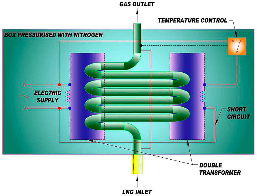
In an electrical vaporizer, the sampled LNG passes through an electrical-resistance heated regulator or, alternatively, through a tube which is heated electrically by induction.
Figure 3 shows an example of an electric induction vaporizer which consists of an electrically conductive tube coil in which LNG flows and vaporizes, this coil being a secondary winding of a transformer. The primary winding of the transformer is supplied by electricity and the induced current that develops in the coil produces the energy necessary to vaporize the LNG sample flow. This heating principle is the only known EN 12838 validated sampling system. The tube coil can be made of copper or stainless steel. Stainless steel is recommended and is used in the new generation of electrical vaporizer.
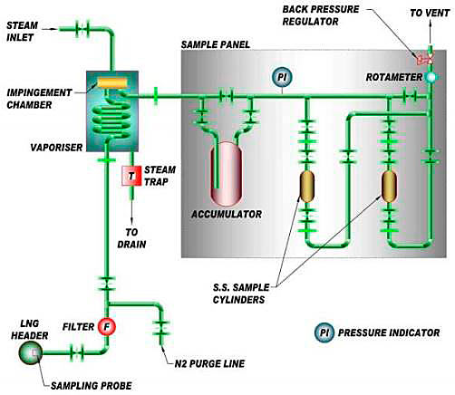
Water or steam vaporizer. Figure 4, a and Figure 4, b show diagrams of vaporizers using water circulation (preferably hot water), or water warmed by steam as heating fluid, or water warmed by an electrical resistance submerged in the vessel, or by direct low pressure steam.
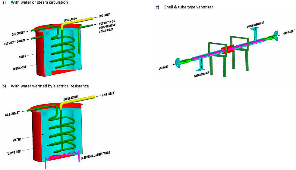
The LNG sample flows in a tubing coil installed in the vessel and vaporizes in it. The coil is usually made of stainless steel (recommended) or, sometimes, copper.
One form of steam vaporizer uses a shell & tube heat exchanger in which the sampled LNG flows through a tube surrounded with a steam or water-heated shell (see Figure 4, c). This is considered outdated.
Auxiliary vaporization control devices
Control devices must be installed to supervise the conditions of vaporization of sampled LNG and to protect the equipment. They are typically installed as follows.
On regasified LNG outlet:
- pressure regulator, or gas flow rate regulator, to control the LNG flow to be vaporized independently of pressure or flow rate in the main LNG pipe;
- anti-pulsation bottle, or mixing accumulator, to absorb the pressure pulses and to maintain gas homogeneity;
- impingement chamber, to prevent the entrainment of possible fine droplets of liquid;
- flow meters and/or flow limiters to control the maximum flow off take;
- pressure meters;
- temperature detection switches, in case of very high gas temperature (example: no more LNG flow) or very low temperature (example: failure of heating device);
- associated devices, such as overpressure safety valve, electro(magnetic) valve to isolate the vaporizer, etc.
On LNG inlet:
- check valve or restriction orifice, to prevent a possible retro-diffusion of vaporized components to the main LNG pipe;
- needle valve, to control the flow of LNG (however, it is better to control gas phase flow in order not to disturb the state of the LNG sampled);
- filter;
- blocking valve to enable safe maintenance of the sampling system by isolation from the liquid LNG;
- a liquid bypass system to give full flexibility to the sampling system in case of maintenance.
On heating fluid (water, steam or electricity):
- temperature regulator, or thermostatic control, to keep constant vaporizing conditions according to the LNG flow;
- thermometer and thermostats in case of failure of heating devices;
- control of the electrical supply of the transformer or of the (submerged) resistance heating element.
Safety devices. Electrical supply and electrical equipment must be of a type designed for hazardous conditions (i. e. explosion proof). For example, the use of an enclosure pressurized with inert gas.
Operating parameters
The following operating parameters can be particularly recommended:
- sample pressure at the sampling point greater than 2 bars;
- vaporizer outlet temperature not below about +20 °C (in practice 50 °C is often used as a set point);
- suitable sample flow rates as these depend highly on the kind of vaporizer used. (inductive heated vaporizers use about 1 m3(n)/h while electrically heated regulators use about 1 500 l/h);
- sample data to be collected during a steady (un)loading rate. This means after ramping up, once full LNG (un)loading rate is reached, and before ramping down.
During sampling it is essential that the process conditions of the sampling system (flow temperature and pressure) remain in a stable and stationary condition. Sudden changes in gas off-take (for example due to the opening of a valve or the removal of a sample cylinder) that will affect the gas flow, should be avoided at all times. These changes can cause the gas to fractionate, resulting in improper sampling and fluctuation in measured heating value.
Gas sample collection systems
To collect either an intermittent or a continuous sample of the vaporized LNG generally two options are available.
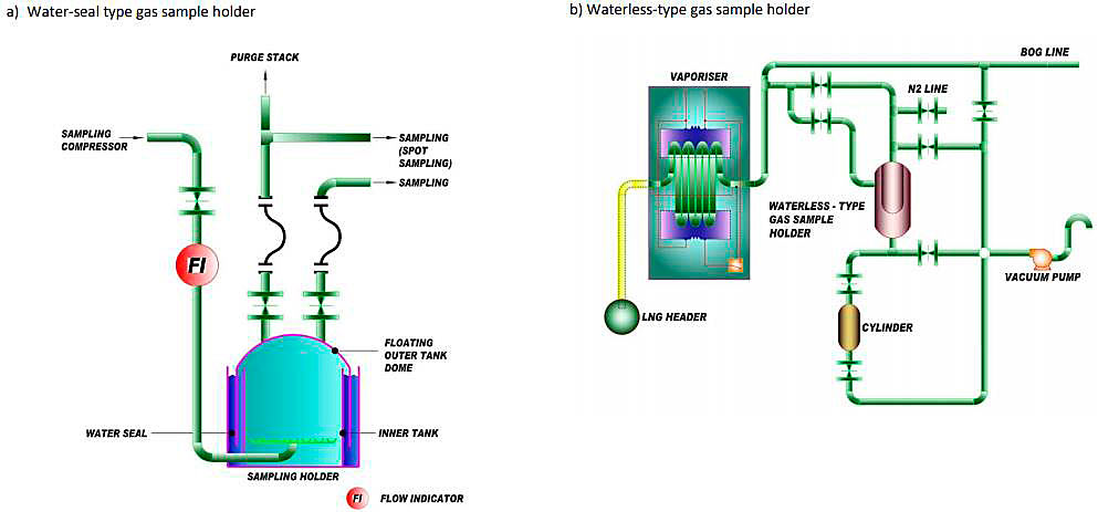
A large gas holder (usually between 0,5 and 1 m3) may be used to store a representative portion of the vaporized LNG during the transfer operation. The characteristics of the gas contained after completion and mixing is representative of the characteristics of the LNG loaded or unloaded. These gas holders can be of several types: water-seal type, the sealing water being saturated with gas by bubbling regasified LNG through it before filling the holder, (see Figure 5, a) or waterless type with a bladder in the gas holder and a vacuum pump (see Figure 5, b).
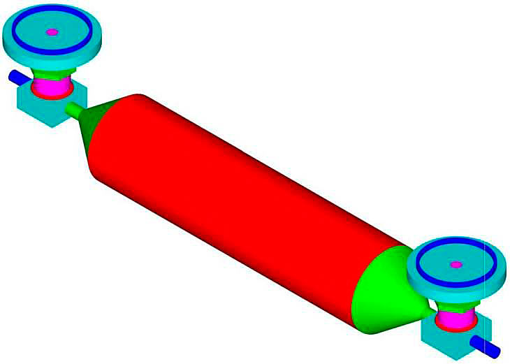
For intermittent sampling a pump can be used that delivers small portions of regasified LNG into a CP/FP sample container. The total amount of such portions depends on the transfer flow and total amount of LNG cargo being transferred. In this case the sample holder generally has a volume between 500 and 1 000 cm3 (see Figure 6).
A third sampling principle that is also based on intermittent sampling is called spot sampling. With spot sampling an appropriate quantity of vaporized LNG is injected in a properly purged sample cylinder. When gas samples are taken in gas sample containers during LNG transfer it should be done with regular intervals, depending on the characteristics of the transfer lines and equipment, the organization of operation in the plant, the duration of gas sample analysis, etc.
Example: the common practice for spot sampling is to take samples during three events only: at 25 %, 50 % and 75 % of loading/unloading operations.
Gas sample conditioning
After the sampled LNG has been vaporized properly, there are two ways of transferring it for analysis: in gas sample container (definition according to ISO 8943: sample container used for the retention of the gas sample and for its transfer to an analyzing instrument) or by direct piping to a gas analyzer.
Gas sample containers
The containers are filled:
- either at the outlet of a gas sample line coming from the gas sample holder normally referred to as a dome sampler, possibly through a booster compressor or vacuum pump (continuous sampling, see ISO 8943) (see Figure 5, a and Figure 5, b);
- or directly, at the outlet of the vaporizer unit. Regasified LNG is fed at specified intervals into a CP/FP sample container during the transfer operation using sample pumps, normally referred to as a piston sampler (intermittent sampling, see ISO 8943) (see Figure 6);
- or directly, at the outlet of the vaporizer unit, periodically during the transfer operation.
This is referred to as spot sampling and is not recommended (Figure 5, a, upper part).
Gas sampling containers should have sufficient capacity for the analyses that follow, for instance 1 liter.
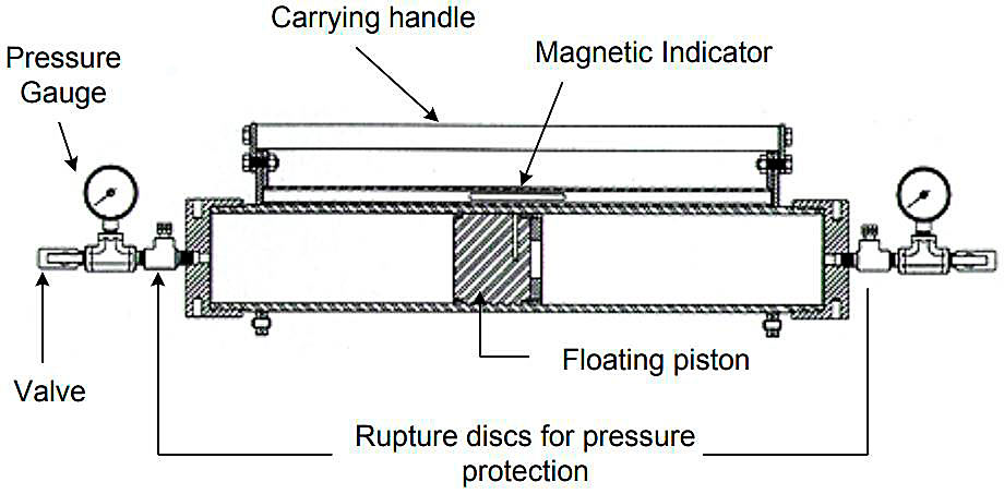
They are generally made of stainless steel and could be either with valves at both ends, as shown in Figure 4, d or could be constant pressure floating piston containers (CP/FP sample container), as shown in Figure 8.
In view of frequent handling of the containers, quick connectors are preferred over screw connectors.
After purging of piping has been performed, several containers may be filled simultaneously or successively (not preferred as it is very important to have the 2 or 3 bottles filled at the same time), according to the installed manifold. It is extremely important to take care that no air enters the container and that the container is sufficiently purged before taking the gas sample to be analyzed.
Direct piping to a gas analyzer
A Gas Chromatograph is directly connected to the vaporizer outlet to perform subsequent analyses during unloading or loading process providing a set of LNG composition data.
In this case, a preferably stainless steel pipe with a small diameter directly connects the outlet of the vaporizer to a manifold at the inlet of gas analyzers.
Read also: Condition Assessment Program for Liquefied Gas Carriers (CAP LNG)
A set of fittings, regulators, valves, flow meters, etc. are necessary to maintain a constant flow and pressure. A Usage of Natural Gas Compressors in the Gas Production Operationsgas compressor may be required in order to make up for the pressure drop in the gas line.
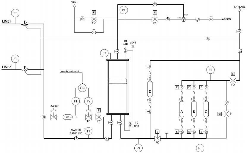
Examples
Examples of general arrangements of sampling devices can be found below.

Performance of the devices
The following remarks can be made about the design of such sampling devices and the choice of the elements which constitute them:
- to prevent or to limit possible contamination or adsorption of the heavy components (C5+) stainless steel is the preferred material for all parts in contact with LNG/NG flowing between the sampling point and the analyzer, since it is less reactive than other materials. It is also recommended that lines, bottles, valves, etc. between the vaporizing device and the analyzer are kept at a constant temperature. During the filling of the gasholder or during the transfer to the analyzer/containers, the gas flow should be regulated to limit outside temperature and gas velocity effects on the adsorption/desorption phenomenon;
- low temperature LNG vaporizers (atmospheric or water at ambient temperature for instance) are not recommended because they are susceptible to fractionation;
- it is important to ensure that the sampling and vaporizing parameters remain as constant as possible during the whole sampling period, mainly LNG or gas flow rate, LNG pressure, and temperature of vaporization.
As the sampling devices have not gone through the same tests, it is difficult to compare their operating performances. Examples of calculation of operating performances of continuous and discontinuous sampling devices are given in European Standard EN 12838.
Note (for information only): New developments. Projects for the verification of different sampling and analysis system are ongoing, e. g., an existing cryogenic liquefier can be used as a reference against which the gas sampling and analysis system can be checked for their accuracy. Certified gas mixtures of known composition and with components normally found in LNG can be liquefied using this liquefier and passed through the sampling system – starting from the sampling probe, vaporiser and gas analysis system – to check how closely the gas composition measured by the gas analysis system agrees with the reference gas composition supplied to the liquefier. Since the gas analysis system is normally calibrated using reference gases, this approach will reveal if (i) the liquid sample passing through the probe to the vaporiser remained representative (i. e. no loss of components) and (ii) the vaporised sample also remained representative (i. e. no fractionation in the vaporizer). Work on verification of different sampling and analysis systems needs to be carried out to check if this approach can be used to verify the performance of different sampling and analysis systems.
Sampling procedure
Sampling period
It is recommended that the LNG be sampled when the LNG transfer flow rate is sufficiently stabilized. So, it is necessary to exclude the initial period, corresponding to the starting of transfer pumps and increase of LNG flow rate, until the main pipe is completely full of LNG and until biphasic or overheated LNG contained at the beginning of the operation has been eliminated, and until the full flow rate is established. It is also necessary to exclude the final period when LNG flow rate begins to decrease before stopping completely.
When significant changes in pressure or flow rate occur in the transfer line, it is necessary to suspend sampling temporarily. Sampling can only be conducted during stable unloading/loading flow rate.
Sampling frequency
As far as filling of a gas holder is concerned, sampling is continuous during the sampling period, at a fixed flow rate; spot samples can be collected in addition, in order to control LNG quality and composition and to monitor the transfer operation, but the corresponding analyses are preferably not used for energy calculation.
When regasified LNG is sent directly to an online analyzer, the gas sample analysis frequency depends on the available analyzer (see Gas analysis of LNG on tankers“Analysis of regasified LNG and retained samples”), but typically every 5 to 10 minutes a sample is analyzed by the on-line GC. Generally, these on-line GC’s never stop sampling. It is important to mention that for custody transfer only the samples taken during stable (un)loading operations must be taken into account.
Purging
It is recommended that purging of sample conditioning equipment (line, containers, etc.) is carried out:
- before starting sampling:
- introduction of LNG, vaporization and circulation of regasified LNG in the vaporizer and pipework;
- subsequent discharge of the purge gas either to atmosphere (small gas flow rate) or to the boil-off gas handling system of the plant.
- before filling the gas sample containers:
- connection of the container(s);
- successively filling and emptying each container (3 times or more) before any gas sample is collected;
- isolation and removal of the container(s).
It is advised to keep the sampling system in service between operations, so that the equipment is continuously purged and ready for a new sampling with the same operating parameters.
Sampling parameters
It is important that the operating parameters of the sampling device (pressure, temperatures, flow rates) are kept as constant as possible throughout the sampling period, in order to obtain a smooth operation which enables representative and repeatable sampling.
Utilisation of gas sample containers
Gas samples collected in containers are:
- on the one hand, directly analyzed in order to determine the average composition of LNG transferred;
- on the other hand, possibly given to the other party concerned with the transfer (purchaser or seller according to the type of LNG purchase contract,) or even kept for further investigations, in case of dispute for instance, during a period defined in the contract which may be up to several weeks.
When the sampling device includes a line whereby the regasified LNG is directly piped to the gas chromatograph, an additional system may be designed to collect spot samples (gas sample container filling station) which are then only used for control, these samples being taken on a diversion pipe at the outlet of the vaporizer with the sampling parameters being adjusted accordingly.
Spot sampling device
An appropriate quantity of LNG is injected in a properly purged chamber previously cooled down by LNG circulation. The chamber is thus partially filled with LNG, and then isolated. The LNG sample is then brought to ambient temperature and vaporizes. Thus, the regasified LNG fills the whole volume of the chamber which is designed to withstand the corresponding pressure increase. Gas samples are then withdrawn from the chamber via pressure reducing valves to fill gas sampling containers.