Ship-to-ship LNG transfer operations on tankers involve transferring liquefied natural gas (LNG) from one LNG tanker to another while both ships are at sea.
- Loading and unloading of small scale vessels
- Application of general formula for calculating the energy transferred
- Alternative method for calculating the energy transferred
- Reloading operations in regasification terminals
- LNG sales contract custody transfer checklist
- Loading of LNG Trucks
- Formula for calculating the LNG energy loaded
- Mass of LNG loaded
- Gross Calorific Values of the LNG loaded
- Energy of the returned gas
- Instrumentation used for the determination of delivered energy in truck loading operations
- Mass measurement (static metering system)
- LNG flow measurement (dynamic metering system)
- LNG quality determination
- LNG temperature measurement
- Loading certificate
This is typically done using specialized equipment and procedures to ensure safety and efficiency. It allows for the transfer of LNG between vessels without needing to dock at a terminal.
Ship-to-ship (STS) LNG Custody Transfer Measurement System (CTMS) on Liquefied Gas Carrierstransfer operations enhance the transfer of LNG from one vessel to another vessel. This can be done directly, in open water, but also indirectly by means of intermediate jetty/jetties and/or piping infrastructure.
A basic example of a ship-to-ship operation is the unloading of LNG at a reception place without receiving facility on shore. For this purpose, a FSRU (Floating Storage and Regasification Unit) is used. This vessel receives LNG from another vessel and has regasification facilities on board to regasify the received LNG and to send the natural gas to a (shore) gas pipeline.
For ship-to-ship LNG transfer operations special attention is required with regards to the detailed analysis of the following aspects:
- physical vessel compatibility;
- ship-to-ship communication and cargo management (in particular sloshing limits, boil-off management and cargo transfer rate).
Ship-to-ship operations also require careful monitoring and management of the manifold connection and the mooring/fender arrangement.
The method to obtain the energy transferred in a STS operation depends on the contract between the different parties or the agreed (terminal) rules, but it is usual to apply the standard rules for the unloading of the discharging vessel into the receiving vessel.
For a ship-to-ship LNG transfer operation from a discharging vessel into a FSRU, the seller/discharging vessel is responsible to provide and maintain the custody transfer measurement systems for volume, temperature and pressure determination on board the LNG vessel. The buyer/receiving vessel is responsible for providing and maintaining the system for measuring gas quality if commercially required. This includes a gas sampling system, and an online gas chromatograph or retained samples for laboratory analysis. As some FRSUs are not fitted with systems for measuring gas quality, the following alternatives may be considered:
- the best option is to calculate the estimated LNG quality received. This estimation has to take into consideration the ageing process of the LNG, the LNG quality originally loaded, the voyage duration and the data of the loading Closing Custody Transfer and the STS Opening Custody Transfer. It is common practice that the estimation is done by an independent third party as for instance the independent surveyor;
- an alternative is to use a portable testing apparatus, vaporizer and gas chromatograph to determine the quality delivered;
- the LNG quality originally loaded is considered as being the LNG quality received. This option does not take into account any ageing of the LNG and hence can lead to significant errors;
- the quality of the gas measured in the shore pipeline is considered as the LNG quality received. This is also not the best option, as it is not always possible to determine if the gas in the pipeline has its origin 100 % in the regasified LNG from the STS operation or whether it is a mix of different cargoes.
For ship-to-ship LNG transfer operations from a (regular) LNG vessel into another regular LNG vessel, the custody transfer measurement can be established as follows:
- STS LNG transfer between two (regular) LNG vessels or between a large LNG vessel and a small(er) LNG vessel (split of a cargo in parcels) on sea, i. e., without connection to a shore jetty or pipeline. In this case it is recommended to have a gas sampling and analysis system on board of one of the LNG vessels. Otherwise, one of the above-mentioned methods might be used.
STS LNG transfer between two ships moored at two jetties of a land based (receiving) terminal. In this case the gas sampling system installed on the pipeline(s) of the (receiving) terminal are to be used to determine the LNG quality transferred. It is recommended to use the sampling system which is installed as close as possible to the unloading vessel in case more than one sampling system is available. Due to mixing of different gas qualities (e. g., because of cold circulation), two sampling systems and two quality certificates could be required (one at the unloading ship and one at the loading ship).
Loading and unloading of small scale vessels
Small scale vessels can be defined by various characteristics, such as vessel capacity, flow rate or volume transferred. The typical cargo capacity range for a small-scale LNG vessel is between 200 and 30 000 m3, however many of the vessels under 1 000 m3 are primarily used for LNG bunkering operations. Those with larger capacities, but less than 30 000 m3, transfer cargo to and from LNG facilities equipped with a compatible jetty designed for smaller vessels. These loading or unloading operations will have flow rates varying from 200 to 2 000 m3/hour thus providing the possible opportunity for utilizing flow meters for the custody transfer measurement (see below and Appendix 1). The small-scale LNG transfers can utilize jetty manifolds with hard arms or cryogenic hoses depending on the facility’s design. Although small scale LNG vessels can have atmospheric cargo tanks as well, they mainly consist of type C tanks and can maintain much higher pressures than traditional atmospheric tanks on shore. This must be considered when managing the return vapor flow during (un)loading operations.
(Un)loading of small-scale carriers brings some additional considerations when compared to classical large-scale ship-to-shore transfers. Special attention should be paid when performing small ship operations at a terminal designed for large scale carriers, and modified to accept small scale vessels, e. g., the technical compatibility of the small scale vessel with the large scale terminal. Furthermore, whilst large scale LNG carriers are dedicated to LNG service, small scale vessels may be certified for multi-product service, providing an increased risk of contamination to the terminal. Additional precautions may be considered to prevent contamination of the BOG, particularly when the previous cargo may differ from LNG. It may be prudent to perform a check of the cargo history, and where necessary, perform additional sampling prior to (un)loading if there is any doubt about the previous cargoes.
Application of general formula for calculating the energy transferred
Volume
The volume of the LNG transferred on a small-scale operation is dependent on the measurement capabilities of the vessel and the terminal. Similar to large LNG vessels, the CTMS on board a small-scale vessel consists of a level gauge and calibration tables. As described in Mastering LNG Measurement – Essential Practices and Operational Insights“LNG volume”, the level measured corresponds to an LNG volume as determined in the cargo tank tables. This level measurement is taken before and after the transfer to determine the volume loaded or unloaded. Most of the small-scale vessels dedicated to LNG are equipped with a radar level gauging system and have similar accuracy ranges as large-scale vessels (+/-5 mm). Many of the newly constructed vessels also have a secondary level gauging system that can be either radar or float type (with a lower accuracy range of +/-10 mm), depending on the vessel. Older small-scale vessels designed mainly for LPG service may not be equipped with a secondary level gauging system. In this case, a review of the contractual agreement may be required. The temperature measuring systems on the small-scale vessels are similar to traditional large LNG design (PT100) and have an accuracy range of +/-0,1 °C for -165 °C to -145 °C. One difference is the number of temperature sensors per tank, as the smaller type C tanks will have less than 5 temperature probes per tank as normally required for large scale LNG vessels. In addition, many of the small-scale vessels are not equipped with secondary temperature probes. Both of these points may require attention to standard contract agreements. Unlike the traditional large scale LNG vessel tank design, the smaller type C tanks are capable of managing much higher operating pressures (up to 10 barg). The standard accuracy for the pressure measurement is +/-0,45 % of the full span with a typical range of 0,8 to 6,8 barg. Please note these measurements systems and accuracy ranges are subject to ship design and may vary among the global fleet.
As noted in Mastering LNG Measurement – Essential Practices and Operational Insights“LNG volume” and Appendix 1, the use of in-line flow meters is possible if equipped at a particular loading/unloading terminal. Given the slower transfer rates for small scale operations, this may be a more practical option, however this is still not an accepted industry method for custody transfer although various projects are ongoing to establish LNG flow standards for calibrating LNG mass and volume flow meters. These may contribute to the general industry acceptance of in-line flow meters for custody transfer use (see below).
Density
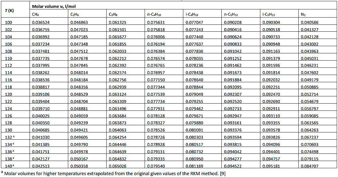
The Revised Klosek and McKinley (RKM) method explained in Recommended methods for calculating LNG“Revised klosek-Mckinley method” may also be applied for density calculations in small scale operations. However, some of these operations may be performed at pressures higher than the atmospheric pressure, corresponding to the saturation pressure for typical LNG mixtures at temperatures of about 110 K (-163 °C). As the RKM does not take pressure into account, it is necessary to adapt this method; the result is known as the Enhanced Revised Klosek and McKinley (ERKM) Method which can be used up to 100 bar. The uncertainty of the well-known RKM method was reported to be 0,1 %. This uncertainty estimate is only valid for calculations around atmospheric pressure; at higher pressures, experimental data have demonstrated that the RKM method is less accurate.
The pressure-dependence of the ERKM method was obtained by fitting an additional term to densities of various typical LNG-mixtures calculated with the GERG-2008 equation of state. Afterwards, the performance of the ERKM method was verified by means of highly accurate experimental (p, ρ, T, x) data sets, which were recently measured. The uncertainty of this new method is the same as of the RKM, namely 0,1 % at temperatures between 100 K (-173 °C) and 115 K (- 158 °C). The uncertainty rises to 0,15 % for temperatures from 115 K (-158 °C) to 135 K (- 138 °C). The limitations of the RKM method in regard of the LNG components do also apply to this method.
Summarized, the pressure and temperature limits are given as:
with an estimated uncertainty of:
The calculation of the new method is as follows:
where:
- ρERKM – density of the LNG according to the Enhanced Revised Klosek and McKinley Method;
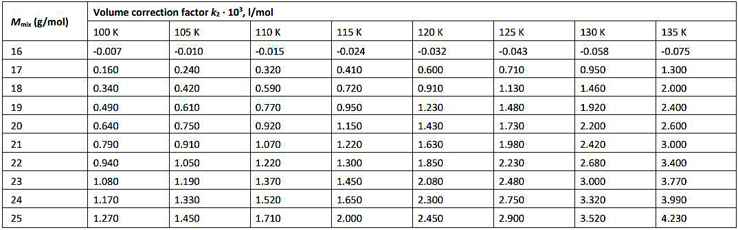
- ρRKM – density of the LNG according to the Revised Klosek and McKinley Method, see tables below for the molar volumes vi and the correction factors k1 and k2 according to the extended temperature range of the Enhanced Revised Klosek and McKinley Method;
- kp – the pressure-related expansion term;
- p – LNG pressure (in MPa);
- T – LNG temperature (in K);
- ps, mix – simplified approach for the saturation pressure of the mixture;
- Tpc – simplified approach for a pseudo critical temperature of the mixture;
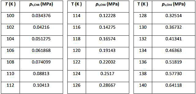
- ps, CH4 – saturation pressure of methane, see below;
- xi – molar fraction of component i;
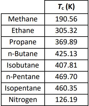
- Tc, i – critical temperature of the pure component i, see below.
ENHANCED REVISED KLOSEK AND MCKINLEY METHOD
Gross Calorific Value
Gross Calorific Value (GCV) quality determination for small scale LNG operations is identical to those used in large scale (un)loading operations. The GCV measurement and calculation methods as specified in Selection principles LNG samples and temperature on tankers“Sampling of LNG”, Gas analysis of LNG on tankers“LNG analysis for quality and measurement impurities”, Recommended methods for calculating LNGData processing and Recommended methods for calculating LNG“Gross calorific value” of this document can be fully applied to small scale LNG operations, but special care should be taken to ensure the proper location and type of LNG sampling probes when used in (re)loading operations at large scale (un)loading terminals. The probe shall be located as described in section Selection principles LNG samples and temperature on tankers“Sampling point”, but shall be located in a position that ensures the probe receives an LNG flow representative of the loading flow. If a single loading line is used, then the sample probe must either be located in main loading header, or the probe must be installed in the line which is in service during the operation. Sample probes shall be bi-directional if used in the reverse flow direction. Similarly, the probe should be located at a suitable point in the process which allows for sufficient pressure to enable correct sampling.
Gas displaced
Differing designs of terminals and carriers servicing the small-scale market allow for different operating conditions and subsequent changes in the way the return gas is handled during a (un)load. These operations may be summarized into the following categories:
1 Closed operations: many small scale vessels are able to operate at much higher cargo tank pressures than traditional large scale carriers. As such, there may be occasions where a vessel elects to (un)load without the vapor return connected. In this case, the formula for determining the total energy loaded may be simplified to:
2 Free flow gas return: the gas displaced during the (un)load flows to/from the terminal under differential pressure and may be considered equivalent to a traditional large scale (un)load.
3 Forced gas return: during (re)loading operations it may be required to lower the temperature of the loaded LNG by reducing the cargo tank pressure using the ship’s or terminal’s blower(s). This operation will result in significant volumes of return gas being sent to the terminal and resulting in a change in composition due to flashing inside the cargo tanks. More details on how to take this into account can be found below.
4 Loading with flash drum: for terminals equipped with a flash drum onshore, it is possible to reduce the LNG pressure and associated temperature before loading (hence reducing the saturated vapor pressure of the LNG), by using a blower installed onshore. Since the flashing takes place in the flash drum onshore, there is no significant increase in the gas return flow from the ship and the gas displaced can be considered the same as the free flow gas return method described above. However specific care should be taken to ensure that any LNG sampling point is located downstream of the flash drum to measure the composition of the LNG to be loaded post-flashing.
Uncertainty of volume measurement
The uncertainty figures provided in section Recommended methods for calculating LNG“Volume” for the volume measurement are those typical for large scale LNG carriers. For small scale vessels, the individual cargo tank uncertainty, the accuracy of the level measurement, and a reduced number of cargo tanks, may all contribute to an additional overall uncertainty.
These factors should be considered when determining the overall uncertainty.
Alternative method for calculating the energy transferred
As the flows are generally quite small (typically 200 to 2 000 m3/h) compared to large scale LNG transfers (over 10 000 m3/h), there might be potential for future use of LNG flow meters (ultrasonic/coriolis) to determine the volume transferred, instead of using the cargo tank tables of the small scale LNG carrier, see also Appendix 1.
Note (for information only): New developments. A new LNG flow facility for calibrating LNG mass flow and volume flow meters has been constructed with traceability for LNG flow rates from 5 to 25 m3/h with a gravimetric measurement. Currently, a new project is focusing on extending the flow rate traceability to 200 m3/h (with the option to extend to 400 m3/h). A different project is focusing on extending the flow rate traceability from 500 up to 1 000 m3/h with a new traceability route using laser doppler velocimetry.
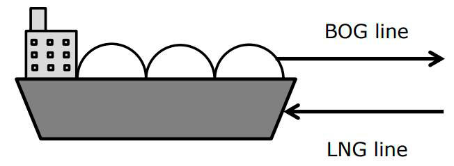
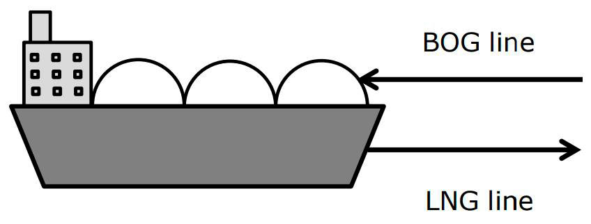
Once mass or flow meters are installed in both LNG and BOG lines, the determination of the energy transferred can be performed by using these measurements taken in the input and output flows of the ship, as shown in figures 1 and 2. The LNG meter has to be cold and completely filled before starting the operation to have a correct measurement.
The total quantity of energy transferred can be calculated by using the following formula:
and
where:
- VLNG line – Volume of LNG determined by the mass or flow meter in the LNG line, in m3.
- DLNG line – Density of the LNG, in kg/m3, determined from the LNG composition and the temperature at the mass/flow meter.
- GCVLNG line – Gross Calorific Value of the LNG, in MJ/kg.
- VBOG line – Volume of BOG determined by the mass or flow meter in the BOG line (applying the necessary compensation for pressure, temperature and compressibility factor), in m3(n).
- GCVBOG line – Gross Calorific Value of the boil-off, in MJ/m3(n).
Reloading operations in regasification terminals
Regasification terminals are designed to receive LNG carriers and unload their cargo. Some of them have recently been adapted to diversify their activities such as for (re)loading operations. However, the operational conditions during a reloading operation at a regasification terminal may differ from those at a liquefaction terminal.
Particularly, the temperature and pressure of the LNG to be reloaded are usually higher than at a liquefaction terminal. For safety and efficiency reasons, carriers may require decreasing the final LNG temperature, which is generally achieved by keeping the pressure low in their cargo tanks by sending a significant amount of return gas to the receiving terminal with the ship’s blower(s). Due to this LNG transfer operation with negative pressure differences, the reloaded LNG will be flashing (excessive boiling) in the ship’s cargo tanks, resulting in a difference between the final composition of the LNG reloaded in the ship and the LNG quality obtained from the sampling system of the terminal. This phenomenon is similar to the natural ageing of LNG during a ship’s voyage. The difference between these two LNG compositions may introduce a significant systematic error in the estimation of the energy transferred and hence may have a negative impact on the energy balance of the terminal.
This error could be avoided by calculating the LNG density and GCV of the actual LNG composition in the cargo tanks instead of the composition determined in the terminal’s pipelines before the ageing. However, as LNG carriers are generally not equipped with LNG composition determination devices, an alternative to estimate the LNG composition could be the application of a mass balance to the ship, for which a proper measurement of the gas return flow and quality would be required, in addition to the devices already used in the LNG Custody Transfer Handbook. This mass balance is fully explained in Appendix 17 and provides an iterative calculation method for determining the LNG quality in the ship’s cargo tanks after the reloading operation.
Note: ultrasonic flow meters are typically installed and are commonly used to measure the gas return flow. As the BOG volume error has a negligible impact on the overall uncertainty in the molar balance, a meter for process indication and process control purposes can be accepted for this application, having an uncertainty of about 2 % in the nominal flow range up to 5 % in the lower flow range.
An alternative way of taking into account this change in quality during reloading operations, could be to apply a correction factor to the total energy transferred based on the total quantity of gas returned from the ship to the terminal. When loading with a positive pressure difference between the terminal’s LNG storage tanks and the General Overview of LNG Cargo Tanks (Typical Operations)ship’s cargo tanks (similar to loading at a liquefaction terminal or loading an LNG ship without using the ship’s blowers), there will only be minor flashing and ageing of the LNG, hence the total gas return quantity will be close to the volume of gas displaced. In this case the correction factor remains 1 and the total energy transferred can be calculated by using the general formula as displayed in section Mastering LNG Measurement – Essential Practices and Operational Insights“General description of the measurement”. However, the more gas is returned from the ship to the terminal (e. g., by using the ship’s blowers), the more ageing and the more impact on the quality of the reloaded LNG, which will translate into an increasing correction factor for the total reloaded energy. As example (based on a number of performed reloading operations at different regasification terminals), the correction factor may vary from 1 up to 1,0025 (= 0,25 % more energy transferred) with the total quantity of gas returned varying from (close to) the volume of gas displaced up to 7,5 times this volume.
The application of the appendix 17 to calculate the LNG quality reloaded (or even the LNG volume reloaded in accordance with the simplified method), will affect the loading documents, so all parties involved (regasification terminal operator as well as terminal user which has a contractual relationship with the terminal operator) shall agree in advance of the reloading operation about the information to be included in the loading documents (i. e. measured or calculated data) in order to avoid any possible confusion or discussion.
LNG sales contract custody transfer checklist
The following is a tabulation of custody transfer issues to consider for inclusion in an agreement for purchase and sale of LNG.
Definitions and Units of Measure:
- Energy units: British Thermal Unit, BTU (or metric equivalent, e. g., kJ, and their multiples, MMBTU or GJ).
- Calorific Value: gross (or net), by volume and by mass, reference temperature for combustion.
- Calorific Value units (BTU/kg, BTU/m3(n), BTU/scf, MJ/kg, MJ/m3(n), etc.).
- Reference temperature and pressure for volume (normal or standard conditions).
- Volume units (normal or standard cubic meter or standard cubic foot).
- Temperature (degrees Celsius).
- Pressure (Pa, bar or psi).
- Mass (kg).
- Density (kg/m3).
- Wobbe index.
- Mole fraction.
- Significant figures.
LNG Quality Specifications:
- Upper and Lower Limits for:
- Gross Calorific Value (or Net).
- Wobbe Index.
- Density at temperature.
- Composition limits:
- methane;
- ethane;
- propane;
- i-butane;
- n-butane;
- i-pentane;
- n-pentane;
- hexane plus;
- hydrogen sulphide;
- carbonyl sulphide;
- mercaptan sulphur;
- total sulphur;
- oxygen;
- carbon dioxide;
- nitrogen.
- Contaminants particulates:
- water;
- mercury;
- oil.
Transferred LNG Energy Quantity Determination:
- Ship provisions.
- Shore provisions.
- Calculation methods (Revised Klosek-McKinley, ISO, HIZA, etc.)
Vapor Displaced, optional: Gas to Engine Room:
- Consideration in Quantity Determination.
- Impact of delay of LNG transfer.
Measurement:
- Ship measurement devices.
- Shore measurement devices.
- Measurement device accuracy, repeatability (certificates).
- Calibration of measurement devices, analyzer, tank gauging standard, method.
Frequency of calibration:
- Independent surveyor.
- Standards and guides (GIIGNL Custody Transfer Handbook, ISO, etc.).
- Condition of ship, shore at gauging prior to and at completion of LNG transfer (e. g., ship’s trim and list).
- Level measurement device specification, identify primary and secondary level gauge.
- Verification of consistency in comparison.
- Tolerance of difference.
Pressure measurement:
- Measurement device specification.
- Each ship tank.
- Witnesses to measurement (opening and closing custody transfer surveys).
Method of recording:
- Number of gauge readings, time interval.
- Manual, electronic.
LNG Sampling:
- Location.
- Timing, frequency/interval.
- Flow-proportional.
- Basis for rejection (accuracy).
- Method of sample vaporization.
- Method of analysis (gas chromatograph).
- Location of analyzer (i. e., laboratory).
- Reserve samples – quantity, retention period.
Buyer/Seller obligations and rights:
- Ship tank gauging – level, temperature, pressure, list, trim, correction (tables) for secondary level gauge.
- Barometric pressure gauging.
- LNG sample collection.
- Boil-off sample collection.
- Sample analysis.
- Certification – tank gauge tables, instrument calibration.
- Witness calibration, measurement.
- Independent surveyor.
- Costs.
- Notification.
- Records preservation.
Actions Upon Deviation:
- Failure of instruments.
- Uncertainty in measurements, readings, calculations.
- Off-specification.
| Example certificate framework. Energy transfer determination | |
|---|---|
| QUANTITY | UNITS |
| Liquid volume before loading/unloading | m3 |
| Liquid volume after loading/unloading | m3 |
| Liquid volume transferred VLNG | m3 |
| Density DLNG | kg/m3 |
| Mass of the liquid transferred | kg |
| Gross calorific (heating) value GCVLNG | MMBTU/kg GJ/kg MWh/kg |
| Energy of LNG transferred | MMBTU GJ MWh |
| Energy of gas displaced (optional, see Recommended methods for calculating LNG“Energy of gas displaced from the LNG tanks”) Egasdisplaced | MMBTU GJ MWh in kg equivalent LNG in m3 liquid equivalent LNG |
| Energy of gas consumed as fuel on board ship during (un)loading operation (optional, see Recommended methods for calculating LNG“Energy of gas consumed as fuel by the LNG carrier”) EgastoEngineRoom | MMBTU GJ MWh in kg equivalent LNG in m3 liquid equivalent LNG |
| Net energy transferred E | MMBTU GJ MWh |
The quantities expressed in kg equivalent LNG or in m3 equivalent LNG are used for customs purposes only.
Please refer to flowchart, Volume measurement methods of LNG transferred“Flowchart for determining the volume of LNG transferred”.
Loading of LNG Trucks
An LNG truck loading facility delivers LNG to a specially designed (or converted) LNG truck (or LNG container) that is suitable for transport of LNG by road, rail or sea. The typical LNG tank capacity of an LNG truck is in the range of 25 m3 to 50 m3.
There are no internationally accepted design standards applicable for LNG truck loading facilities, so designs may differ between terminals. In general, LNG is supplied to the facility using loading or send-out pumps and transferred to the truck/container via cryogenic hoses or hard arms. Loading rates vary between terminals, but are typically up to 100 m3/h. A vapor return hose/arm is normally connected to the truck to manage the BOG generated during loading. However, not all truck designs require a vapor return connection.
The loading operation usually includes the following stages:
- In case of the use of vapor return, decompression of the LNG truck.
- An initial period, corresponding to the starting of loading where the LNG flowrate is low (cooldown).
- An increase of LNG flowrate until the nominal flowrate (ramp-up).
- A stable period at the constant nominal flowrate (loading).
- A final period when LNG flowrate begins to decrease before stopping completely (ramp-down).
Control and supervision of the loading process is carried out by the facility operator and/or truck driver.
Static measurement using a weighbridge is the most commonly used method for measuring the quantity of loaded LNG. As an alternative, dynamic measurement could be used.
Formula for calculating the LNG energy loaded
The determination of the transferred energy differs from the methodology used for LNG carriers. Since the determination of the quantity of LNG loaded into a truck is normally based on a direct measurement of mass, calculation of the LNG density from gas composition and temperature is not normally required.
In case of a static measurement (weighbridge), the calculation for the loaded energy can therefore be simplified as follows:
where:
- E – the total net energy transferred from the terminal to the LNG truck in kWh.
- MLNG – the mass of the LNG loaded in kg – the total mass weighted after loading – the total mass weighted before loading.
- CGVLNG – the gross calorific value of the LNG loaded in kWh/kg.
In case of a dynamic measurement, the calculation for the loaded energy can be as follows:
where:
- E – the total net energy transferred from the terminal to the LNG truck in kWh;
- MLNG – the mass of the LNG loaded measured by the flow meter in kg;
- CGVLNG – the gross calorific value of the LNG loaded in kWh/kg;
- Egas returned – the terminal during loading in kWh.
Mass of LNG loaded
The mass loaded is automatically determined using a weighbridge or a mass flow meter (coriolis). The determination of the mass loaded by using a volumetric flow meter requires the calculation of the LNG density Density calculation is required when volumetric flowrate meters are used. Refer to section 9. for applicable density calculation methods.x. The Selection principles LNG samples and temperature on tankerstemperature used for the LNG density calculation should preferably be measured as close as possible to the truck loading station. If this is not possible, the temperature of the LNG in the LNG tank can be used.
If the mass loaded is determined using a weighbridge, the mass measured before loading must be measured before the decompression of the LNG truck.
Gross Calorific Values of the LNG loaded
Gross calorific value (GCV) determination for LNG truck loading is identical to large scale (un)loading operations. The GCV measurement and calculation methods specified in Gas analysis of LNG on tankers“LNG analysis for quality and measurement impurities”, Recommended methods for calculating LNG“Data processing”, and Recommended methods for calculating LNG“Gross calorific value” can be fully applied to LNG truck loading.
Energy of the returned gas
Determination of the energy returned is only required in the case of dynamic measurement of the quantity of the LNG loaded. For mass measurements (static), determined by a weighbridge, the mass of the displaced gas is automatically compensated for by measuring prior to commencement and following completion of a load.
If the energy of the returned gas must be determined, it may be assumed that the returned gas has a predefined composition according to the terminal rules (e. g., pure methane). This assumption will have a negligible effect on the overall uncertainty.
The energy of the displaced gas is calculated as follows:
where:
- Vgas returned – the volume of measured returned gas from the LNG truck to the Terminal in m3(n);
- GCVreturned gas – the gross calorific value of the returned gas in kWh/m3(n).
Instrumentation used for the determination of delivered energy in truck loading operations
For the determination of delivered energy in truck loading operations, the following instrumentation devices are used. Parties should agree in advance what actions will be taken in the event of a failure of the instrumentation.
Mass measurement (static metering system)
The quantity (mass) of the LNG delivered to the truck is usually determined by a weighbridge as the difference between the mass reading before and after the loading. This quantity is normally rounded to the nearest ten kilograms (10 kg).
Weighbridges, typically consisting of a metal structure on a concrete base with semi-recessed mounting, may be dedicated to individual loading bays or a common weighbridge may be shared between multiple loading bays.
The weighbridge shall comply with metrological requirements, both in its commissioning and in its periodic verifications. For mass measurement, it is recommended that the accuracy of the weighbridge never exceeds ± 0,20 %.
A certificate of calibration shall be issued by a certified independent party. The recalibration frequency of the weighbridge depends on the metrological requirements of each region, country, company, etc.
LNG flow measurement (dynamic metering system)
An alternative to static measurement by a weighbridge is the use of dynamic metering systems.
LNG flow metering using mass flow (coriolis) meters and/or volumetric (ultrasonic) flow meters is gradually being introduced into applications of LNG fiscal measurement in small scale operations.
The recalibration frequency of the flow meter depends on the metrological requirements of each region, country, company, etc.
Coriolis meters measure mass flow directly, therefore a density calculation is not required. These mass meters have better accuracy than volumetric flowrate meters, but they have size and pressure drop limitations. On the other hand, installation of straight pipes upstream and downstream is not required, reducing pipe length and installation costs compared to ultrasonic flowmeters.
For the determination of delivered quantity in truck loading operations, flow meters Density calculation is required when volumetric flowrate meters are used.x must be installed both in LNG and BOG lines. A flowmeter in the LNG pipeline to measure the amount of LNG delivered to the truck and, another one, to measure the amount of BOG returned to the facility. The amount of BOG should be subtracted from the total LNG amount transferred. Pressure differential devices as orifice plates can be used to measure the BOG amount, as any inaccuracy in measuring BOG flow may be considered negligible in the calculation of net amount transferred.
Read also: Cargo Handling Systems and Specialised Equipment on LNG LPG Carriers
Flow meters and their associated instruments (transmitters, flow computer, etc.) have to comply with metrological requirements for custody transfer purposes as well as following international recommendations and standards. In Europe, the system should be certified according to the Measuring Instrument Directive (MID) for liquids other than water.
A new LNG flow facility for calibrating LNG mass flow and volume flow meters (up to 100 m3/h) has been constructed with traceability for LNG flow rates from 5 to 25 m3/h with a gravimetric measurement. Currently, a different project is aiming to extend the flow rate traceability from 500 up to 1 000 m3/h with a new traceability route using laser doppler velocimetry.
Note that LNG flow meters need single-phase flow (no BOG bubbles) to yield maximum metrological performance. Therefore, in the case of LNG, operation at temperature and pressure beyond its bubble point must be avoided and guaranteed. Consideration shall be given to the design and start-up sequence of the truck loading facility to ensure the lines are completely filled and cold prior to start of measurement.
LNG quality determination
Quality determination requires the installation of an LNG sampling and NG analyser system. The location of this equipment may differ per terminal. Some terminals have dedicated LNG samplers and analysers located at the truck loading facility, whilst others make use of equipment installed at another location e. g., an LNG tank/jetty.
Other terminals, e. g., liquefaction plants, may elect not to measure the LNG composition, but measure only the LNG quantity delivered at the loading facility, and use an assumed composition to the determine the energy delivered.
Any agreement regarding the location, and requirements for LNG analysis is purely dependent on the Terminal Rules.
Sampling
The LNG sampling techniques required for a Truck Loading facility are identical to those described in Selection principles LNG samples and temperature on tankers“Sampling of LNG”.
The sampling of LNG shall adhere to the following principles:
- taking a representative sample of LNG;
- complete and instant vaporization;
- conditioning the gaseous sample (e. g., ensuring constant temperature and pressure) before transporting it to the analyzer and/or sampler.
LNG temperature measurement
The temperature of the LNG delivered in truck loading operations is usually measured either by using the temperature gauging devices located in the pipeline from storage tanks to the truck loading bay, or by using the temperature probes placed in the storage tank used for delivering LNG to the truck.
In order to determine the LNG temperature in the storage tank of regasification terminals, an arithmetic average of the liquid temperature is calculated using the reading at individual temperature sensors, placed at different heights in the tank.
Temperature gauging devices are generally three or four wire platinum resistance temperature sensors (usually Pt 100). Thermocouples are not used for LNG temperature measurement because they are less sensitive at very low temperatures and often give a less accurate measurement than platinum resistance probes.
The accuracy of the temperature gauging devices is identical to those described in Selection principles LNG samples and temperature on tankers“Liquid temperature”.
Note that the influence of temperature measurement accuracies on the density determination of LNG delivered to the truck is very significant.
Loading certificate
An automatic custody transfer system is typically available in the control room. All signals coming from the field devices are transmitted to the Loading Control System for monitoring, controlling and determining the quantity and quality of LNG delivered to the truck. The Loading Control System is normally able to manage all the required documentation and produce printed reports.
Before the first loading, the tanker owner must make available to the facility the required information for truck approval (technical characteristics, certificate of capacity issued by an authorized entity, etc.).
Before starting the custody transfer operation, the loading limit must be established according to the regulations of each region (e. g., ADR – The European Agreement concerning the International Carriage of Dangerous Goods by Road, for the European Union).
After completion of the loading operation, quality and quantity documents are generated. As a general rule, the facility operator must provide the truck driver with the product delivery slip (loading certificate), the consignment note (transport document) and any other documents that are required by regulations, before leaving the facility.
It is also advisable to complete a before/during/after loading checklist and add it to the above documentation. These documents must normally be signed by the loading facility and the transport company.
The documents could include information relating to the consignee, shipper, carrier enterprise and information about quality and quantity of the LNG delivered to the truck.
The following is a tabulation of issues to consider for inclusion in these documents, for measurement purposes.
Identification
- date and time;
- loading Reference code;
- data:
- consignee,
- shipper,
- carrier enterprise Truck company,
- truck codification,
- trailer codification,
- product description,
- UN number according to the United Nations Committee of Experts on the Transport of Dangerous Goods.
Cargo Quality Data
- LNG composition;
- Net Heating Value;
- Gross Heating Value;
- LNG temperature;
- LNG density;
- Pressure;
- Gas density;
- Wobbe Index;
- Methane Number with the calculation method;
- Sulphur.
Load Quantity Data
- Gross weight after loading;
- Net mass loaded;
- Energy loaded;
- Volume loaded;
- Gas Volume (LNG loaded equivalence in gas at standard conditions);
- Maximum filling (%).