This article delves of professional marine radio service, communication, exploring its fundamental structure, diverse functions, and critical details that underpin the seamless operation of ships and vessels worldwide.
- General Regulations
- Authority of the Master
- Ship’s Radio Licences
- Documents to be carried
- ITU Lists
- Inspection
- Unauthorized Transmissions
- Tests
- Order of Priority of Communications
- Ship power Supplies
- Circuit Breakers and Fuses
- Battery Types
- Battery Capacity
- Primary Batteries
- Antennas
- VHF Antennas
- MF/HF Antennas
- Antenna Maintenance
- Traffic Charging
- Radiotelegrams
- Traffic Charging Worksheet (1.25)
Also an in-depth look at the specific frequency bands used for different types of marine communication, including VHF, UHF, HF, and satellite bands.
General Regulations
Authority of the Master
The radio service of a ship is under the supreme authority of the Master or other person responsible for the ship.
Ship’s Radio Licences
These are normally issued by the national Administration, but can also be issued by another office or institute on behalf of the national Administration. The licence should be displayed near to the radio equipment and shows the following:
a) Name of ship.
b) Call sign and relevant identification numbers.
c) Owner’s name.
d) Frequencies.
e) Transmitter output powers.
f) Classes of emission.
g) Public correspondence category.
h) Other conditions under which the station is to be operated.
The licence should be permanently displayed near the main ship station control point.
Documents to be carried
The Radio Regulations require that ships for which a radio installation is required by international agreement carry the following documents:
- Ship’s Radio Licence.
- Radio Operators’ Certificates.
- GMDSS Radio Log – book.
- ITU List of Call Signs and Numerical Identities of Stations used by the Maritime Mobile and Maritime Mobile – Satellite Services.
- ITU List of Coast Stations.
- ITU List of Ship Stations.
- ITU List of Radiodetermination and Special Service Stations.
- ITU Manual for Use by the Maritime Mobile and Maritime Mobile – Satellite Services.
Other international and national regulations require additional documentation and publications to be carried, e. g.:
- Radio Safety Certificate.
- Antenna Rigging.
- List of spares and where kept.
ITU Lists
The ITU information lists included in the compulsory carriage requirement for ITU documentation on board a ship station contain:
List of Call Signs and Numerical Identities:
- Coast and ship station numbers.
- Ship earth station numbers.
- MMSI numbers.
- SELCALL numbers.
List of Coast Stations:
- Working and broadcast frequencies.
- Traffic list times.
- Charges for all countries.
- Stations with DSC facilities.
List of Ship Stations:
- Ship call signs.
- Ship earth station numbers.
- Classes of communication.
- AAICs.
List of Radiodetermination and Special Service Stations:
- Radio/radar beacons.
- Time signals.
- Weather bulletins.
- Navigational warnings.
- Medical advice.
Inspection
Surveyors or inspectors from the appropriate shore-based authorities, i. e., local maritime transport Administration or telecommunication Administration, may inspect the ship station, including the documentation and the equipment.
Note:
- Unlicensed use of radio equipment is a punishable offence in most countries.
- Under Port State control procedures, the ship may be detained in port if the radio equipment does not meet the SOLAS carriage requirements.
Unauthorized Transmissions
Stations are forbidden to:
a) Make unnecessary or superfluous transmission.
b) Transmit false or misleading signals.
c) Transmit without using their identification.
It is also useful to remember that you should only radiate as much power as is necessary to ensure a good communication link and that, before transmission on any frequency or channel, you must ensure you are not going to interfere with transmissions already in progress.
Tests
All tests must comply with established regulations.
Test Transmission
These should be kept to a minimum and should, if possible, be carried out using an artificial antenna (dummy load) and/or reduced power. Distress frequencies should not be used unless absolutely necessary. Test or tuning signals should be for less than 10 seconds and should include the call sign or other identification.
Daily Tests
- DSC – Without radiation-Use built-in test facility.
- Batteries – On-/Off-load voltage checks – Fully charge if necessary (see later section on batteries and maintenance).
- Printers-Check sufficient paper-DSC-NAVTEX-Telex-SATCOM.
Weekly Tests
- DSC-Live call to coast station.
- Reserve source of energy – other than battery.
- Survival craft VHF – not on channel 16.
Monthly Tests
- EPIRBs – Use built-in test facility – do not radiate.
- SARTs – Using the facility.
- Batteries – Check condition of all batteries – EPIRBs SARTs – Reserve – VHF.
- In the case of EPIRBs and SARTs you should also check the security of the, i. e. for corrosion or damage.
Order of Priority of Communications
The order of priority for communications Communications includes radiotelegrams, radiotelephone calls and radiotelex calls.x in the Maritime Mobile Service and the Maritime Mobile-Satellite Service is as follows:
- Distress calls, distress messages, and distress traffic.
- Communications preceded by the urgency signal.
- Communications preceded by the safety signal.
- Communications related to direction finding.
- Communications relating to the navigation and safe movement of aircraft during SAR operations.
- Communications relating to the navigation, movements and needs of ships and aircraft, and weather observation (OBS) messages destined for an official meteorological service.
- ETATPRIORITENATIONS – Radiotelegrams relating to application of the United Nations Charter.
- ETATPRIORITE – Government radiotelegrams with priority and Government calls for which priority has been expressly requested.
- Service communications relating to the working of the telecommunication service or to communications previously exchanged.
- Other Government communications, ordinary private communications, RCT RCT (Red Cross Telegrams) refer to telegrams concerning persons protected in time of war by the Geneva Conventions of 12 August 1949. RCT radiotelegrams will be accepted in accordance with ITU–T Recommendation F.1, and will be charged in accordance with ITU–T Recommendation D.40.x radiotelegrams and press radiotelegrames.
Ship power Supplies
To comply with the SOLAS Convention, ships are required to have available a supply of electrical energy sufficient to operate the radio installation, and to charge any batteries used as part of reserve source of energy, at all times while at sea.
Reserve sources of energy are a mandatory requirement and must be capable of powering the radio installation in the event of failure of the ship’s main and emergency source of electrical energy for purpose of conducting distress and safety radiocommunications. The reserve sources of energy have to be capable of operating simultaneously the VHF radio installation and, as appropriate for sea area or sea areas for which the ships is equipped, either the MF radio installation, the HF radio installation or the ship earth station and other necessary loads, such as navigational equipment linked to the radio installation or essential emergency lighting for the installation.
Alternative sources of energy to power of ship earth station should also be sufficient for all of the ancillary equipment necessary for its normal functioned, including the antenna tacking system where provider.
Read also: Empowering Global Communication with INMARSAT Satellites in shipping
The reserve sources of energy should be adequate for at least one hour or six hours, depending whether the ship is provided with an emergency source electrical power complying with regulation 42 or 43, as appropriate, of SOLAS chapter II-1. The reserve power supply must be independent of the propelling power of the ship and the ship’s electrical system.
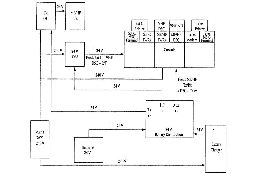
The radiocommunication equipment may operate either from the ship’s d. c. or a. c. mains supply (often stepped down to 24V d. c.), or from 24V d. c. supplied by of bank batteries. The batteries often from a reserve sources energy with are on a “Float Charging System” so that, should the mains supply fail, the batteries automatically take over. The float charging system ensures that the batteries are always fully charged. If necessary, a “boost” charge can be given at any time, i. e., a higher current charging supply is applied to secure a quicker charging period.
Circuit Breakers and Fuses
Many modern bulkhead switches and distribution boxes have overload trips which can be reset at the push of button. However if after resetting, it “trips” again then you probably have a fault which needs tracing and rectifying.
Most equipment is individually fused. Fuses are used to protect the equipment and the operator in the event of a fault.
When replacing blown or suspect fuses, observe the Following safety procedures:
- The power supply MUST be switched off before taking a fuse out for testing.
- Replacement fuses MUST have the correct rating.
Battery Types
Battery cells provide electrical energy by means of an electrochemical reaction involving the exchange of electrons between the positive and negative electrodes (or plates) of the cell through an electrically conducting ion-exchange medium, in liquid or paste form, called the electrolyte. When an external electrical load is connected, a current is generated as electrons transfer from the negative electrode, or cathode, to the positive electrode, or anode.
Note:
- Console needs battery supply to operate MF/HF + telex, will not operate on mains alone.
- Printer + VDU run off 240 V monitor socket.
As the cell delivers electrical energy, the chemical composition of electrodes is changed; the capacity of the cell will eventually be exhausted when no further chemical change is possible. For the class of batteries constructed from primary cells, the battery is of no further use once this point is reached since recharging is not a practical proposition.
For the class of batteries constructed from secondary cells, however, the chemical reaction involved is easily reversed if electrical energy is fed back into the cells. The battery can then be used again. Thus secondary cells are used in rechargeable batteries.
The defining characteristic of the various types of cell is the cell voltage, which is open-circuit potential difference, also called the electromotive force (emf), between the electrodes and the electrolyte.
Battery Capacity
The ampere-hour capacity (AHC) of a battery of cells indicates the amount of energy it can deliver over a standard discharge period, usually 10 or 20 hours.
A battery, in good condition, rated at 140 ampere-hours at the 10 hours rate, for example, can deliver 14 amps for 10 hours, more than 7 amps for 20 hours, but something less than 28 amps for 5 hours.
Primary Batteries
Primary batteries have a single lifespan, meaning that they cannot be recharged and therefore require periodic replacement. Although not rechargeable, primary batteries have compensating advantages in many applications where small size and long storage life are the main consideration. Over the smaller range of battery sizes, the ratio of power output to weight or size is typically superior for primary cells. In addition, primary batteries generally have superior storage characteristics.
Antennas
An antenna is an element capable of radiating and intercepting radio waves. The radiation and reception of radio waves are most effective when the antenna is in resonance. Various resonant configurations can be achieved by antennas with dimensions of ¼ or ½ wavelength, or multiples thereof.
It is more important for a transmitting antenna to be in resonance than for a receiving antenna since transmitter performance can be badly degraded by a mismatched antenna. Older types of transmitters could be damaged by feeding into a poor antenna but modern designs usually incorporate automatic protection circuitry to shut down the transmitter or reduce power to a safe level if necessary.
VHF Antennas
As the wavelength in the maritime VHF band (154-162 MHz) is around 2 m, it is possible to use ¼ and ½ wavelength antennas. The most basic design is the dipole, which consists of a split ½ wavelength element connected at the centre to a balanced feeder cable. Figure 2 shows some simple examples of VHF antennas, including the artificial ground-plane antenna and the VHF rod-antenna-typically a 1,5 m fiberglass pole contains a dipole antenna.

It is important that VHF antennas are mounted as high as possible and in a position free from obstruction by the ship’s superstructure.
MF/HF Antennas
In the MF/HF bands, however, wavelengths vary from 180 meters (1 650 KHz) to about 12 meters (25 MHz). Resonant ¼ or ½ wavelength antennas covering the entire frequency range are therefore not possible. The problem can be eased by using a number of separate antennas, each covering a single band or several harmonically related bands.
An antenna tuning unit (ATU) is usually used to “match” the transmitter output to the antenna over a wide range of frequencies. In effect, the ATU uses electrical components, i. e. coils (inductors) and capacitors, to achieve a resonant electrical length in combination with the actual physical length of the antenna.
Nevertheless, it must be noted that the efficiency will vary over the frequency range because the radiating efficiency is still determined by the physical length of the antenna. Even if the ATU can match a very short antenna to the transmitter, for example, the overall efficiency will be poor.
Connections between the transceiver, the ATU and the main antenna should be kept as short as possible to ensure the efficient transfer of energy to the antenna.
If there is a simple space between existing masts or to erect special antenna masts, then the main or emergency antenna may be a wire antenna. A wire antenna may be stretched between masts or between a mast and another elevated part of the ship’s superstructure. An example is shown in Figure 2 of a T-type antenna, although inverted L-types may also be found.
However, because of the lack of space on board many modern ships, most GMDSS fittings use vertical whip antennas for MF/HF transmissions. For example, the main HF transceiver may use an 8 m whip, the 2 128 KHz watchkeeping receiver may use a 4 m whip and the NAVTEX receiver may use a 1 m whip. A separate 6 m whip is commonly used for the MF/HF DSC receiver.
Antenna Maintenance
All antennas should be kept clean, salt deposits removed, and feeders and brackets checked regularly.
The various insulators must also be checked for cracks and must be cleaned regularly. The safety loop on a wire antenna prevents the antenna from falling if undue strain (e. g., from high winds or build-up of ice) is placed upon it; the weak link should break in the first instance rather than the antenna.
A spare wire antenna has to be carried and should be stored in an easily accessible place so that it can rapidly be erected in an emergency.
It should be remembered that dangerously high voltages and RF currents are present close to the main antenna. Ideally, the ATU and the link to the main antenna should be protected to prevent anyone touching the feeder.
Before doing any maintenance work on any antenna, ensure that the power is removed from the equipment and that the main fuses are removed and kept in a safe place (a pocket is often the simplest and safest place).
As a further precaution, the antenna should be also grounded, since RF energy can still be induced in the antenna from other antennas on board or on nearby ships.
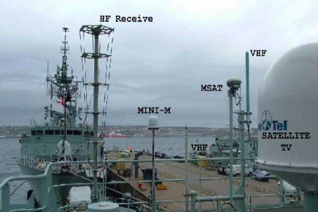
Even though a shock from an induced RF voltage may only startle rather than cause direct injury, an accident may still result though, for example, falling from a ladder, or dropping tools from a height. An antenna rigging plan should be available showing the positions of the various antennas. Figures 2 and 3 show examples of maritime antennas.
Traffic Charging
All public correspondence connected through terrestrial circuits or through satellite networks must be charged for.
Charges for calls via coast stations can be found in the ITU List of Coast Stations.
Terrestrial charges may comprise:
- the land-line charge – in special drawing rights (SDR) or gold francs (GF);
- the coast station charge;
- the ship charge;
- any charges for special services;
- any local taxes, e. g., Value Added Tax (VAT).
In general, operator-connected calls have a minimum 3 minute charge and 1 minute incremental steps thereafter while automatic telephone and telex calls have 6 second charge with 6 second incremental steps.
Messages send via Inmarsat-C are charged on the number of kilobits of information transmitted (1 kbit = 1 024 bits or 128 characters, about 25 words). This information is shown in the log file. A charging scheme of 0,17 SDR per block of 256 bits (quarter of a kilobit) as the CES charge and 0,15 SDR per block of 6 second for the land-line charge is typical.
It will be interesting: Basic transmitters and receivers in shipping
A number of companies provide radio traffic accounting services. A list of the companies, identified by their Accounting Authority Identification Code (AAIC), designated to cater for ships of the various flags states is published in the ITU List of Ships Stations. Many of the larger accounting authority companies provide computer software to help with reconciling the radio traffic accounts.
Note: Different Administrations use different currencies when dealing with radio traffic charges.
These currencies are usually the special drawing right (SDR), the gold franc (GF), the US dollar ($) and the pound sterling (£); exchange rates are published daily in Lloyd’s List. The gold franc is linked to the SDR by a fixed ratio, i. e., 3,061 GF = 1 SDR.
With a computerized accounting system the currency can be selected as required. Details of the accounts can also be downloaded, usually every month, to disc and sent to the accounting authority. The company will send updated software, typically once or twice a year, to take account of any charges which have occurred.
Radiotelegrams
Radiotelegrams
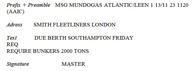
All radiotelegrams, whether sent by terrestrial means or via Inmarsat, must follow the following format:
- PREFIX.
- PREAMBLE.
- ADDRESS.
- TEXT.
- SIGNATURE.
The PREFIX is used to indicate the type of telegram, e. g.:
- P – Private correspondence;
- MSG – Messages to/from Master on ship’s business;
- OBS – Reports to Met Office;
- AMVER – To AMVER Centre in New York.
The PREAMBLE completed by the operator and consists of the following:
| OFFICE OF ORIGIN | Name and call sign of vessel |
| NUMBER | Telegrams are numbered in a separate daily series to each station, commencing at 00,01 UTC. |
| WORDS | Indicates the number of chargeable and actual words or groups of characters in the address, text and signature. Any word or group with more than ten characters is charged as two words. |
| DATE/TIME | Date and time (in UTC) when the message was handed in for transmission. |
| SERVICE INSTRUCTIONS | An abbreviation denoting a special service such as pre-paid replies, special routing of the radiotelegram, special delivery instructions, and will ALWAYS INCLUDE THE ACCOUNTING AUTHORITY IDENTIFICATION CODE (AAIC) AS THE LAST ITEM. |
Inmarsat Code 15
Radiotelegrams sent via satellite circuits follow the same format as for terrestrial transmissions, but the 2-digit code 15 may be used to expedite the message.
Example:
An example of commercial telegram is shown below:
Traffic Charging Worksheet (1.25)
Some specimen exam questions are given below which candidates should work through, using the standard documentation, and check with the instructor:
- Your ship is in the Atlantic Ocean Region and you make an automatic telephone call to a subscriber in Sierra Leone via Goonhilly CES. What is the charge in gold francs if the the call duration is 4 minutes?
- You make an automatic telex call via Sentosa CES to a subscriber in Cyprus. If the call lasted for 26 seconds, what charge would be levied?
- Excluding VAT, what is the charge for a 54 second automatic telex call on HF from a UK-registered vessel to an address in Paris, assuming that the call is made via Portishead Radio.
- What is the charge, excluding VAT, for a 2,5 minute automatic telephone connected call via Goonhilly CES ship to ship?
- What is the charge for a standard 5 minute MF R/T link call via a Norwegian coast station to a subscriber in Oslo?
- Your vessel is 10 miles off Cullercoats Radio (UK) and you wish to make a person to person radio telephone call to a subscriber in Italy.
- Which frequency band would you use?
- What is the total cost of this call if the call duration is 5 minutes?
- What is the minimum charge of a transferred charge R/T call on MF to an Australian subscriber?
- What is the cost, in gold francs, of an Inmarsat-C telex call of 2,5 kbits to a subscriber in Liberia?

- General operator’s Certificate for The Global Maritime Distress and Safety System, Course + Compendium, Model Course IMO 1.25, Printed by PMS UK Ltd London, 2004.
- European Radiocommunications Committee ERC Decision of 10 March 1999 on the harmonised examination syllabi for General Operator’s Certificate (GOC) and Restricted Operator’s Certificate (ROC)(ERC 99 01).
- IMO GMDSS-Handbook, London, U. K., 2004.
- Norcontrol Capella GMDSS Simulator, Technical documentations, Kongsberg Maritime Ship Systems, Norway, 2005.
- INMARSAT MARITIME COMMUNICATIONS HANDBOOK – INMARSAT – London, U. K., 2005.
- Seafarers’ Training, Certification and Watchkeeping CODE 1995 (STCW Code 95, published by IMO, London, 1996), – Part A Mandatory standards regarding provisions of the annex to the Convention Chapter IV Standards regarding radio personnel.
- Seafarers’ Training, Certification and Watchkeeping CODE 1995 (STCW Code 95, published by IMO, London, 1996), – Part B Mandatory guidance regarding provisions of the STCW and its annex; Chapter IV Guidance regarding radiocommunication and radio personnel.
- V. Pipirigeanu, M. Udrea, Introducere in GMDSS – Sistemul Mondial de Primejdie si Siguranta Maritima, Ed. Europolis, Constanta, 2002.
- Graham D. Lees, William G. Williamson, Handbook for Marine Radio Comunication, e d. LLOYD S OF LONDON PRESSLTD., 2004.
- ITU Manual for Use by The Maritime Mobile and Maritime Mobile Satellite Services, 2006.
- IAMSAR Manual – International Aeronautical and Maritime Search and Rescue Manual, 2001.
- C/S G.003 – Introduction to Cospas-Sarsat System, (G3OCT28.99D Issue 5 – Rev. 1 October 1999), C/S Documents published by Cospas-Sarsat in Handbook of Regulations on 406 MHz and 121,5 MHz Beacons, (1999);
- Tor R. Kristensen – An Introduction to GMDSS, revised GOC Edition, – 7th edition, Leknes, Norway, 2007.
- C/S T.001 – Specification for Cospas-Sarsat 406 MHz Distress Beacon, (T1OCT30.99D – Issue 3 – Rev. 2 October 1999), Documents published by Cospas-Sarsat in Handbook of Regulations on 406 MHz and 121,5 MHz Beacons (1999).
- IMO SOLAS (SAVE OF LIVE AT SEA), Consolidated Edition, London, 2001.