Unlock the operational insights of natural gas heaters on LNG carriers with our comprehensive guide. Explore typical systems, precise control mechanisms, setup procedures, and seamless transitions from manual to automatic operation for optimal performance. Dive into the intricate world of LNG carrier heating systems today.
Reference: SIGTTO “LNG Shipping Suggested Competency Standards”, Sections:
1 Have an awareness of their purpose and operating principles.
2 Know and understand their principles, operating parameters, the outlet requirements and limitations:
- temperature requirements.
3 Know and understand operational requirements and procedures:
- the relationship between steam supply and capacity of heater;
- condensate level control;
- outlet temperature control mechanisms and methods used to control vaporiser outlet temperature;
- setting up;
- starting;
- changing from manual to automatic operation (use of automatic controllers);
- shutdown.
4 Know and understand alarm settings and resulting actions.
General description of typical systems
Three common systems are as follows:
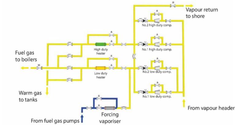
- two steam heated boil off/warm-up heaters fitted, one sized for LD (fuel gas compressor) use and High Duty Compressor(s) on the Liquefied Natural Gas Carriersone sized for HD (vapour return compressor) use;
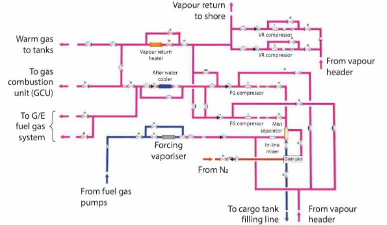
- one steam heated warm-up heater and one water cooled after cooler/heater;
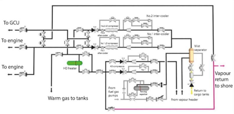
- one steam heated warm-up heater and LD compressor water cooled inter and after cooler/heaters.
BOG is normally supplied to the E/Rat +25 °C and gas for warming-up operations is supplied at a maximum of +80 °C.
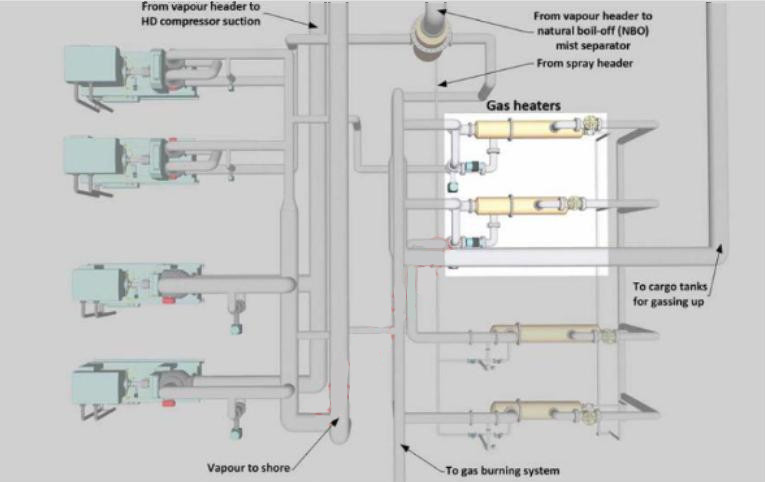
Two steam heated boil-off/warm-up heaters are usually fitted, one sized for LD (fuel gas) use and one sized for HD (vapour return) use.
The heaters are used as follows:
- low duty heater, used in conjunction with the LD compressors, supplies heated BOG to the consumers;
- high duty heater used for heating the LNG vapour, which is delivered by the HD compressors at the specified temperature for warming up the cargo tanks before gas freeing.
One steam heated warm-up heater and one water cooled after cooler/heater.
The cooler/heaters are used as follows:
- After cooler/heater is used in conjunction with the LD compressors supplies heated BOG to the consumers;
- vapour return heater used for heating the LNG vapour, which is delivered by the HD compressors at the specified temperature for warming up the cargo tanks before gas freeing.
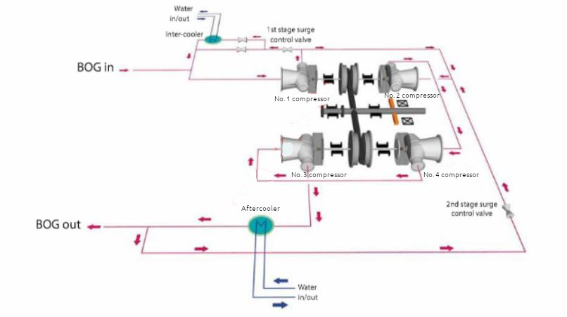
One steam heated warm-up heater and LD compressor water cooled inter and after cooler/heaters.
The cooler/heaters are used as follows:
- inter and after cooler/heaters, used in conjunction with the LD compressors, supply heated BOG to the consumers;
- high duty heater used for heating the LNG vapour, which is delivered by the HD compressors at the specified temperature for warming up the cargo tanks before gas freeing.
The heaters and inter/after-cooler/heaters will normally be of the shell and tube type with automatic temperature control. The heating medium will either be steam or, in the case of the intercoolers, water.
Note that on some LNGCs, to ensure a better temperature differential for stratification during inerting operations, the heaters may be used for heating the IG.
When returning heated vapour to the cargo tanks, the temperature at the heater outlet should not exceed the manufacturer’s recommendations. This value is typically between +50 and +80 °C and avoids possible damage to the cargo piping insulation, safety valves and the cargo tank itself.
| Cargo Heater – Typical Details | |
|---|---|
| type | horizontal shell and tube heat exchanger |
| rated capacity | 25 500 kg/h (normal condition) |
| vapour inlet temperature | minus 125 °C (-125 °C) |
| vapour max outlet temperature | +80 °C |
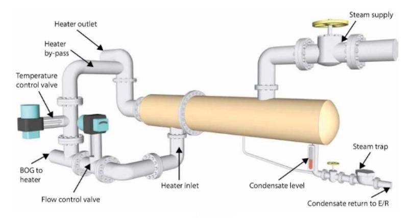
Each heater or cooler is a shell and tube type heat exchanger. The heating surface consists of straight tubes arranged so that cargo vapour flows through the tubes and steam condenses outside of the tubes. The end covers are welded to the tube sheets but are flanged so that the tubes can be inspected or plugged on board the ship if required.
In practice, the high duty heater is used for warming-up operations and the Use of Vaporisers on Liquefied Natural Gas Carriersvaporiser is used for purging (gassing-up) operations.
Control of the heaters
De-superheated steam at approximately 10 bar is supplied from the main steam system to the heaters. Where fitted, the inter and after coolers are supplied by fresh water at approximately 5 bar. The gas flow and temperatures of the BOG to the consumers and the LNG vapour for warming up are controlled by the IAS.
All alarms and trips are generated locally and are monitored by the IAS. If the condensate level reaches the high level, the heater is tripped by the IAS.
To prevent the formation of ice, the vapour heaters should be thoroughly preheated with steam before the admission of LNG vapour.
Setting up/starting
The temperature in the steam exhaust line and the vapour outlet should be monitored when the heater is put into operation.
All alarms and trips should be operational and monitored.
Basic operating procedure for the warming-up operation
The manufacturer’s instructions and the ship’s operations manual should always be referred to for specific instructions. However, a typical operation will run in the following manner:
- open the shell side vent valve;
- open the shell side condensate valves and check the drains;
- crack open the manual steam supply valve;
- when all the air has been expelled from the shell, shut the vent valve;
- when water has been drained from the shell, shut the drain valve;
It should take approximately 30 minutes to warm up the gas heater to the designed temperatures and pressures.
- slowly open up the steam inlet valve;
- set the NG lines for the appropriate operation;
- in the CCR, set the controls for the heater to the “On” position on the IAS.
- open the instrument air supply to the heater controls;
- check the condensate level in the sight glass;
- set the temperature and condensate level controller;
- open the gas inlet and manually operated outlet valves;
- monitor the gas vapour outlet and condensate return temperatures.
Changing from manual to automatic operation (use of automatic controllers)/shutdown
While manufacturers’ manuals and the ship’s operating manual should be reviewed for specific instructions, what follows is a typical set of operational procedures.
On completion of the operation:
- switch the auto-control to manual;
- close the gas supply and outlet valve on the heater;
- close the steam supply valve to the heater when the temperature at the heater outlet is above 0°C;
- open the steam side vent and then open the drain when all the steam has vented.
The steam condensate from the heater is returned to the drain system via the cargo steam drain cooler and cargo condensate tank. The condensate tank is fitted with a gas detector sampling point.
Basic operating procedure for fuel gas burning
The same procedure is followed for venting and warming through the heater, except that the temperature control is set for a gas outlet temperature of approximately +30 °C.
Depending on the system fitted, the NG lines will be set to use one of the Low Duty Compressor(s) on the Liquefied Natural Gas CarriersLD compressors to deliver the gas to one of the heaters. One heater will be used for this operation, with the second heater on standby
When the heater has been vented and warmed through, proceed as follows:
- slowly open the manually operated steam inlet valve;
- check the condensate level;
- set the NG vapour lines as detailed for the appropriate operation;
- open the vapour outlet valve and the vapour inlet valve;
- in the CCR/ECR, set the controls for the gas heater on the IAS.
- open the control air supply to the gas heater controls;
- set the temperature and level controllers to the correct settings for gas burning at +30 °C;
- monitor the gas vapour outlet and condensate temperatures.
On completion of the operation:
- after the LD compressor has been shut down and the gas supply valve to the engine room shut, close the inlet valve to the heater;
- shut the steam inlet valve;
- open the steam side vent and then open the drain valve when all of the pressure is off the heater.
Alarms and resulting actions
The following are typical alarm and trip parameters:
| Gas heater outlet pressure | High alarm: 950 mbar |
| Low alarm: 30 mbar | |
| Gas heater condensate level high | |
| Gas heater outlet temp | High alarm: +80 °C |
| Low alarm: 0 °C | |
| Gas heater common trip | |
| Gas heater condensate temperature low-low trip | +80 °C |
| Gas heater condensate level high-high trip | |
| Gas heater manual trip | |
| Gas heater outlet temperature high-high trip | +100 °C |