This article describes the power system design, installation impacts and applicable auxiliary systems. The results of a comprehensive economic model of competing propulsion systems are presented and analysed, further demonstrating the benefits and advantages. No less important in today’s world are the environmental effects of transporting this “green fuel” across the oceans – a characteristic where, without complex, heavy and expensive additional plant, the gas turbine reigns supreme.
- Summary
- Introduction
- Gas turbines
- Machinery for LNG Carriers
- The gas turbine electric concept
- Simple cycle or coges
- Simple cycle system
- Combined cycle system
- Prime mover description
- MT30 gas turbine
- 501 Auxiliary Gas Turbine
- Combined cycle machinery
- Realising the benefits
- Cargo capacity
- Installation
- Environment
- Economics
- Conclusions
The LNG shipping industry is undergoing rapid expansion with larger LNG carriers, over 200 000 m3 capacity, predicted to be ordered in the very near future. Alongside these vessel size and market transformations, alternative LNG carrier propulsion technologies are being proposed and indeed ordered. Traditionally, LNG carriers have been powered by a steam boiler and turbine, fuelled by a combination of boil-off gas and heavy fuel oil (HFO). Steam propulsion systems are heavy and expensive to install, consume valuable cargo space and require sea-going engineers with steam qualifications, which are becoming increasingly scarce.
Summary
In close consultation with large oil companies, noted industry experts and key shipyards, Rolls-Royce has developed a number of alternative LNG carrier propulsion systems that deliver increased cargo carrying capacity, operational flexibility and through life cost savings. These are modern and highly efficient integrated systems that provide a reduction in operating costs when compared with existing steam and other proposed alternatives. The result is a range of power and propulsion systems based on the state of the art MT30 gas turbine that fully meet the requirements of large (145 000 m3 > 250 000 m3) LNG carriers.
Introduction
Pressure from environmentalists and pure economics has driven the global power generation industry to increasingly turn to gas fuel. This pressure, coupled with an ever increasing electricity demand, will lead to a significant increase in natural gas consumption over the next 25 years. The gas fields and gas markets are not co-located which requires a growth in natural gas transport infrastructure. Whilst some of this gas will inevitably be supplied via pipelines, the larger distances between supply and demand will require high capacity LNG trains with dedicated export and import terminals. Shipping experts, owners and operators are constantly evaluating available propulsion system alternatives for LNG carriers, seeking to secure an economical advantage in this evolving market. Propulsion systems based on the modern MT30 gas turbine offer significant economic advantages whilst fully meeting the requirements of these specialised vessels.
Gas turbines
Gas is the ideal fuel for a gas turbine and the proposal to power an LNG carrier with gas turbines is not new. In the mid 1970’s, the LNG carrier “Lucian” was mechanically powered by a heavyweight (non-aero derivative), industrial, recuperated gas turbine. Modern aero-derivative gas turbines are very different to heavyweight industrial gas turbines and it is the recent gas turbine technology developments of the offshore oil and gas industry, including dual fuel applications that are of more significance to the LNG shipping industry today. Gas turbines are predominantly developed and produced for civil and military aerospace although it has long been the practice to utilise the developed technology in the power generation, offshore oil and gas and marine markets.
For example, the Olympus gas turbine, originally developed for Concorde has proven to be extremely successful as a land based electricity generator and as the standard naval warship boost engine of the 1970s.
In the oil and gas industry, the RB-211 gas turbine, developed for a variety of aircraft including the ubiquitous Boeing 747, has demonstrated outstanding reliability and efficiency. Fuelling options for the industrial RB-211 include gas, diesel fuel, and dual fuel variants. The dual fuel technology, developed in the early 1980s, has achieved millions of hours of operation and is that required for LNG carrier Overview of Alternative Propulsion Systems for the LNG Vesselpropulsion systems. The introduction of the modern Trent family of engines marks a significant advance in gas turbine technology. The Aero Trent 800 went into service in 1996 and has proved to be one of the most reliable aero engines in the world. Trent 800 technology has been rapidly transferred to both the industrial and marine markets. Recently selected for the Dolphin gas pipeline from Qatar to the UAE, the Industrial Trent offers up to 60 MW of power and utilises low emissions combustion systems. The MT30 is the marine version of the Trent 800 and has already achieved remarkable market success since introduction in 2002. The MT30 development programme commenced in 2000, with the first engine running to its full power of 36 MW in September 2002.
Uniquely, the MT30 brings the performance and reliability of a modern aero engine into the marine sector as soon after the introduction of the aero-parent as possible and with the absolute minimum of change. The result is a marine engine that has 80 % parts commonality with the parent engine, with the distinction of component coatings appropriate to the marine environment.
Machinery for LNG Carriers
LNG ships are unique for a number of reasons. They are the only type of ship that can (and does) use the cargo as a source of fuel. Moreover, this fuel is environmentally friendly and relatively cheap. Historically, there has always been an advantageous price differential for gas, and all dual fuel concepts primarily burn gas to make use of this cost benefit, with the environmental and engine life factors as a significant bonus. The steam turbine ships that have dominated the industry burn blends of fuel oil and gas, in order to match the operating profile and price/availability of gas. No reliquefaction plant is fitted on steam ships, the “waste boil off gas” is used to raise steam for propulsion, and when not required for propulsion, the steam raised is dumped in the condenser.
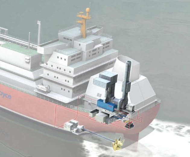
By comparison with the alternative propulsion systems being proposed for future LNG carriers, steam installations are inefficient, large and heavy. Using gas as the primary fuel and diesel only as back-up fuel provides an economic advantage. The dual fuel electric concept, be it powered by either dual fuel gas turbines or dual fuel diesel engines derives an advantage from the bulkiness of either steam or slow speed diesel powered ships. The vast reduction in volume required to accommodate the machinery and electric drive propulsion system allow cargo capacities to be increased for a given hull, or a reduction in displacement for a given cargo volume. Thus the key characteristic is power density and the MT30 is the most power dense marine engine available. A graphic of the proposed gas turbine machinery aboard an LNG carrier is shown in Figure 1.
The gas turbine electric concept
Electric propulsion is a key factor in maximising the overall system flexibility and reliability. By employing an integrated power and propulsion system, any prime mover can provide power to any electrical consumer from navigation lights to propulsion motors. Prime movers are arranged in a power station configuration with the most appropriate engine or engines engaged to match the load requirements of the vessel across its operational profile. Equally important to the economic evaluation of the concept is the reliability of the gas turbine generators. Modern aero engine technology has evolved over the last 30 years to the point where Rolls-Royce has achieved a dispatch reliability of at least 99,9 % for its highly rated aero engines.
In an LNG carrier application, the MT30 will operate predominantly on gas and at powers significantly less than the aero parent. This operation will return unparalleled levels of reliability and longevity, supporting the concept of single engine operation at sea, albeit with appropriate system redundancy. The maintenance of modern gas turbines is a feature that can easily be misunderstood, as the support regime required is inherently different to that of diesel engines. Aero derivative gas turbines are by definition designed to operate with minimum attention between defined operating periods, and their continual development has progressively extended the operating periods to many years of operation.
Simple cycle or coges
In many industrial applications, waste heat recovery in a combined cycle system is used to boost thermal efficiency from about 40 % to over 50 %. Similar systems are used on some cruise ships and known as COGES (Combined Gas Turbine Electric and Steam) systems. Clearly the 10 % thermal efficiency advantage of COGES systems over a simple cycle gas turbine system in an LNG carrier installation is compelling, but perhaps the choice is not as clear-cut as it seems. Comparing propulsion system efficacy to various alternatives can be complex and include many initial and through-life considerations. A comprehensive comparison demonstrates that the COGES system has much merit but that simple cycle systems have three major advantages which either “narrow the gap” or reverse the relative positions between them. One further consideration is that the LNG carrier will rely on the additional COGES system’s functionality to perform the service condition (19,5 knots), which will degrade the overall propulsion system availability.
Ultimately, the propulsion system decision can only be made as part of a techno-economic study by the end user, when specific (rather than generic) project profiles, prices and requirements can be analysed. A considerable variation in financial results is gained by using different values for the boil off gas, which is specific to each project, route and end user.
From both an operational and efficiency point of view it is preferable to have at least two prime movers in a combined configuration to match the different power levels required by ship operations. Thus the developed systems include at least two gas turbine alternators.
In a COGES system, the exhaust heat recovery system with its incorporated turbo generator serves as a further means of powering the ship, however it is only operational when the main gas turbine is in use. The incorporation of an auxiliary boiler, capable of supplying steam to the turbo generator at times when the main engine is not operational, will add the overall flexibility and redundancy of the system without a large impact on initial cost and weight.
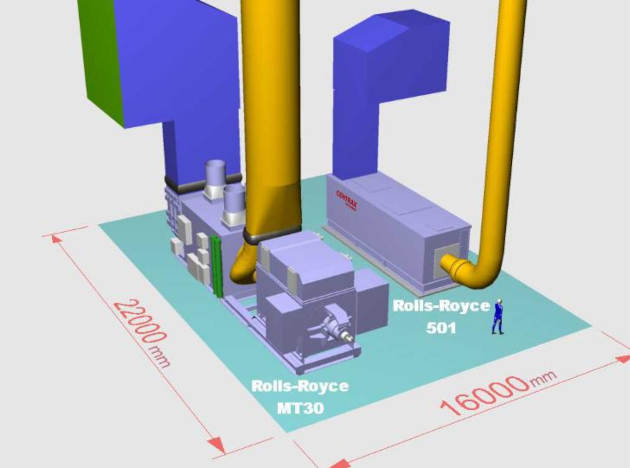
Simple cycle system
Dependent upon vessel size and requirement, power is provided under all normal operations by two simple cycle gas turbines. The main propulsion engine is the Rolls-Royce MT30, rated at 36 MWe in dual fuel form, used for all sea going operations. The auxiliary engine is the Rolls-Royce 501, packaged by Centrax in dual fuel form and rated at 5,5 MWe for all port operations, and as a reserve engine to the MT30. Included in this generic system design is a 1,5 MWe diesel harbour generator, and an emergency diesel which provides additional redundancy and “black start” capability.
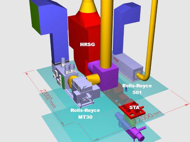
Combined cycle system
Power is provided under all normal operations by a single gas turbine equipped with a heat recovery system, steam turbine alternator and an auxiliary simple cycle small gas turbine. The main propulsion engine is the Rolls-Royce MT30, rated at 36 MWe in dual fuel form, connected to a Heat Recovery Steam Generator (HRSG) supplying steam to a turbo generator sized up to 10,5 MW dependent on vessel size. The auxiliary engine is the Rolls-Royce 501, packaged by Centrax in dual fuel form and rated at 5,5 MWe for port operations, and as a reserve engine to the MT30. An auxiliary boiler is also included to power the steam turbine when the main engine in not in operation. The Rolls-Royce 501 in this application is capable of self-starting (i. e. black start) in addition to the emergency diesel.
Although capable of dual fuel operation (gas and liquid fuel), the gas turbine alternators are primarily fuelled by gas fuel. Two methods of gas fuelling (natural boil off gas, and vaporized LNG) are provided. The natural boil off gas is compressed using a tandem screw compressor, and the forced boil off gas is vaporized at the required pressure through a shell and tube vaporizer. Liquid fuel (Marine Gas Oil) is consumed only in an emergency or when there is no gas on board, as when the vessel is newly built or during transit into or out of refit.
Prime mover description
MT30 gas turbine
The MT30 gas turbine has been marinised to meet the growing demand for higher powers and efficiency, whilst driving down the cost of ownership of propulsion systems within the Naval and Commercial marine markets.
The engine development programme began in June 2000 continuing the Rolls-Royce strategy of developing its core gas turbine technology expertise across a range of markets. The aim was to The New Generation of Liquefied Natural Gas Carriers – Basic Design Philosophydesign an efficient, cost effective and reliable marine prime mover that can be configured for both mechanical and electrical drive.
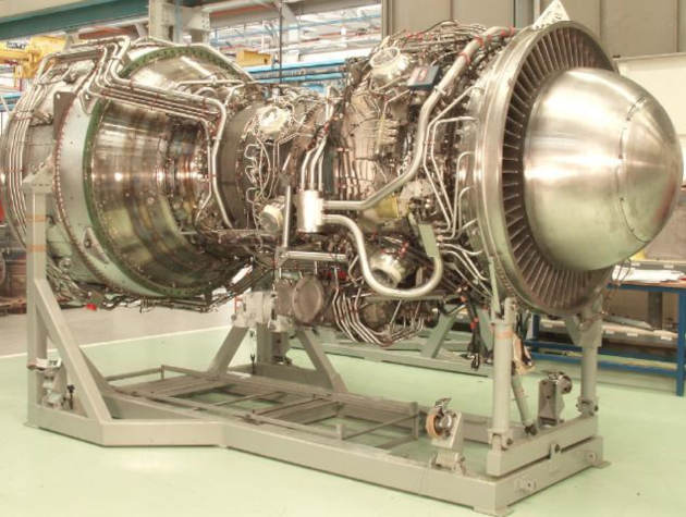
The design of MT30 maximises retention of the aero engine power density and reliability to ensure trouble free operation. The design change from aero parent engine is strictly limited to what is necessary to adapt the engine to its new environment resulting in 80 % commonality with the parent Trent engine. The MT30 gas turbine was introduced to the marine industry in September 2002 and ordered by the US Navy later the same year. In the last 12 months, the MT30 has achieved DNV (Det Norske Veritas) type approval and has completed 1 500 hrs of endurance running for US Navy certification under the auspices of the ABS (American Bureau of Shipping) at the naval rating of 36 MW at 100 °F (38 °C).
The first MT30 engine, prior to despatch, is shown in Figure 4.
1 Dual Fuel Operation
Building on 20 years of experience with dual fuelled gas turbines for the Oil & Gas industry, the dual fuel MT30 will use fuel system hardware derived from the industrial Trent product.
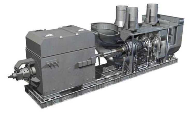
The core dual fuel engine will be packaged in an acoustic enclosure incorporating all ventilation and gas safety systems, to be installed with an alternator on a common baseplate to form an MT30 Dual Fuel Gas Turbine Alternator (GTA) set. The packaged GTA set is shown in Figure 5.
The dual fuel MT30 uses 24 dual passage fuel injectors derived from the industrial Trent to supply both fuels to the combustion chamber.
The use of a two passage fuel injector (one for diesel and the other for gas) allows both fuels to be burnt simultaneously in the engines combustion chamber, enabling the engine to maintain power output whilst changing fuels or burning a mixture of gas and liquid. The engine electronic controller governs the fuel admitted to the engine via electronic metering valves ensure safe operation in all fuelling modes.
The dual fuel GTA package contains all required ancillary systems including:
- Ventilation System.
- Package Coolers.
- Lubricating Oil System.
- Fire Detection & Protection System.
- Gas Detection.
- Compressor Wash System.
2 Performance
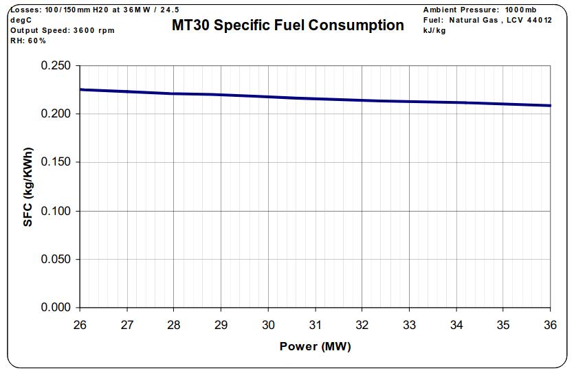
A maximum continuous installed rating of 36 MW is available from the MT30, flat rated with air inlet temperatures up to 26 °C. MT30 will maintain this power running either on gas or liquid fuels, however running on gas is the normal operation as this clean fuel has no harmful contaminants, prolonging the interval between engine overhauls.
On gas fuel the MT30 delivers a thermal efficiency of 42 % at 36 MW and retains market leading fuel consumption characteristics over its optimal power band from 26 to 36 MW. The specific fuel consumption (sfc) characteristic over this power range including generic installation losses is shown in Figure 6.
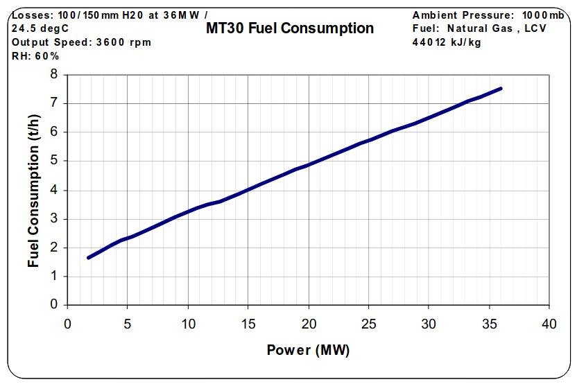
Fuel consumption across the entire operating range of the MT30 is shown in Figure 7.
3 Maintenance
Modern gas turbines require very little routine and periodic maintenance but are removed from the vessel at extended intervals for hot section replacement or complete engine overhaul. As a result on board spares holdings needed for the MT30 are minimal. Most of the onboard maintenance work is limited to visual inspection, safety items and checking fluid levels. Condition Based Maintenance (CBM) is a feature of the engine design, internal condition sensors enable the unit to be serviced on an “on condition” basis, thus minimising maintenance and costs.
MT30 operating predominantly on gas in LNG carrier applications has a design life of 48 000 hours between overhauls with a hot section replacement overhaul required approximately every 24 000 hours.
The MT30 core engine comprises of a gas generator and power turbine unit, weighing approximately six tonnes. The compactness of this change unit requires only a small onboard crane or load carrying beam overhead to transfer the change unit from the enclosure to a transport cradle.
Mounting the gas turbine on the quarterdeck facilitates simple replacement of the core engine owing to the ease of access to the machinery space. Whilst engine replacements are usually scheduled for docking and ship maintenance periods, the ability to exchange engines within a few hours enables replacement to be achieved with minimum disruption during operational periods.
501 Auxiliary Gas Turbine
The Rolls-Royce 501 gas turbine is packaged as a dual fuel gas turbine alternator set by Centrax. The 501 is an aero derivative engine from a successful series of engines that have been in production since 1963. Due to its demonstrated reliability, low routine maintenance and extended time between overhauls, it is ideal for driving electric generators, either for prime power or standby installations.
Total production of this family of engines exceeds eighteen thousand units and includes many hundreds of marine and industrial applications, such as power generation for prime power and stand by, marine propulsion, gas compression and re-injection, etc. Total operating time is in excess of two hundred million hours.
The fuel economy and length of time between overhauls results in very low operating costs (501 gas turbines have typically operated in excess of 35 000 hours between overhauls).
1 Dual Fuel Operation
501 GTA sets have been supplied to many customers in dual fuel format for use in applications where continuous running on either liquid or gaseous fuel with the ability to rapidly change between the two is a requirement. Duties relevant to LNG carriers include power supply aboard offshore units, desert situated power generation and as standby units for nuclear power stations.
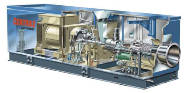
The 501 GTA is supplied packaged in an acoustic enclosure including an alternator, gearbox and all ancillary equipment. The 501 GTA set is shown in Figure 8.
The dual fuel 501 uses 6 dual passage fuel injectors to supply both fuels to the combustion chamber similar to the MT30.
The engine electronic controller governs the fuel admitted to the engine via electronic metering valves ensure safe operation in all fuelling modes.
The dual fuel gas turbine alternator package contains all required ancillary systems including:
- Reduction Gearbox.
- Ventilation System.
- Package Coolers.
- Lubricating Oil System.
- Fire Detection & Protection System.
- Gas Detection.
- Compressor Wash System.
- Starting System.
2 Performance
A maximum continuous rating of 5,5 MW is available from the 501 Gas turbine at ISO Conditions. The 501 will maintain this power running either on gas or liquid fuel, although running on gas will be the norm.
Additionally the 501 includes the capability for use as an emergency power supply allowing consecutive starts with no cool down or restart limitations.
3 Maintenance
Employed as the auxiliary engine, predominantly for port operations, the 501 will usually run only for short periods of the LNG operating cycle. Operating mainly on gas fuel the 501 has a predicted overhaul life of 32 000 hours, which on current operating profiles would not be required in over 40 years of operation. Should the engine require removal the package is designed to allow replacement within a 12-hour period as for the MT30.
Combined cycle machinery
Should a LNG project or shipowner select or prefer a COGES system to benefit from the thermal efficiency gains, a gas turbine alternator with a simple single pressure HRSG and Steam Turbo Alternator (STA) are recommended. Many such installations have successfully featured in offshore, industrial and marine (cruise ship) applications.
The HRSG should consist of a horizontal water tube type heat exchanger arranged in the gas turbine exhaust for either horizontal or vertical gas flow, associated steam processing plant and a steam turbo alternator package. The capacity of the combined cycle generator can be tailored to suit the ship size and corresponding power requirements. Making full use of the energy in the MT30 exhaust can provide a combined output of 46 MW at thermal efficiencies around 50 %.
1 Dual Power operations
As MT30 power output increases the temperature and flow rate of the exhaust gas increases. This exhaust gas flows through the HRSG, increasing the amount of steam generated and raising the output of the STA. The steam system is a closed loop system thereby STA output varies according to GT output power.
To maximize system flexibility, an auxiliary boiler may be fitted, capable of raising steam for supply to the STA at times when MT30 is not in operation. It is specified that this boiler be dual fired (i. e. by liquid and gas fuel) such that it can be used for power generation during port operations.
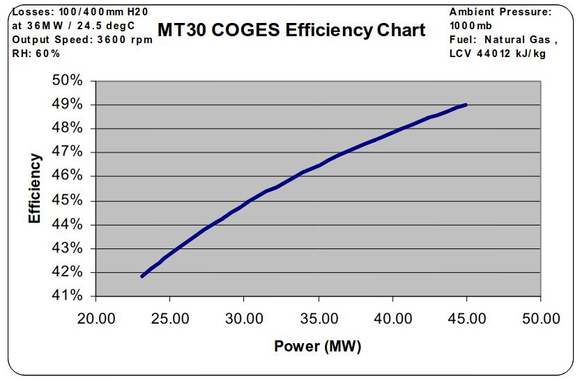
2 Performance
Employing combined cycle generation can achieve large thermal efficiency gains. Figure 9 shows the efficiency of an MT30 COGES system optimized for 46 MW of power generation. Optimization of the combined cycle plant at lower powers will further increase the thermal efficiency lower down the power range.
3 Maintenance
By keeping the combined cycle system as simple as possible the maintenance and reliability of the system are maximized. Onboard spares will be used to repair the system or components at sea for all but major failures. The increased onboard spares holding and the requirement for trained maintenance staff is one drawback of a COGES system.
Realising the benefits
Cargo capacity
The power density of the gas turbines allows them to be mounted on the rear quarterdeck behind the superstructure, and over the mooring deck, as shown in Figure 10.
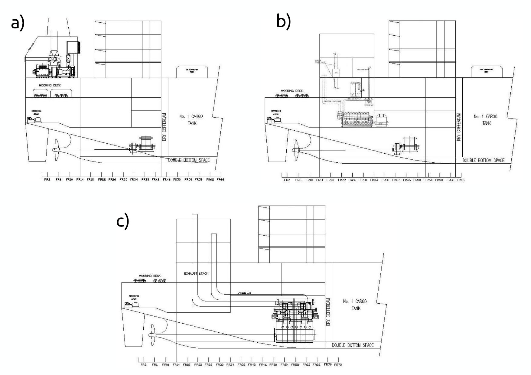
a) Gas Turbine Powered LNG Carrier;
b) Dual Fuel Diesel Powered LNG Carrier;
c) Slow Speed Diesel Powered LNG Carrier
The power station (simple cycle or COGES) is then located away from the traditional machinery spaces with only the shaft line and electric drive components located in the bottom of the vessel. The power distribution system is equally flexible with the switchboards and bulk of electrical equipment conveniently located under the superstructure.
Removing machinery and systems from within the hull to this extent obviously offers the theoretical opportunity to utilise freed space for cargo. However, exploiting this space in an LNG carrier is not straightforward. The part of the ship where this space is now available is aft of the parallel midsection. Here the ship has complex hull geometry necessitating a complex tank design, which in turn has a cost implication. The dimensions of LNG tanks are only flexible within strict limits set by specialist containment system designers and ultimately approved by them in accordance with classification rules. Without the design validation of the ships tank arrangement, any concept is unfeasible.
One solution may be to use the approved dimensions of the existing fore tank in a reverse position to become the new aft tank of a 5 tank ship. However arranged, it is certain that full utilisation of the freed machinery space cannot be achieved – but a large proportion of it can be – and this is where the principal advantages are realised.
Whilst the design of tank system and propulsion system have to be finalised to meet exacting specifications, the concept to utilise freed space is valid, and has been demonstrated in the innovative ships being built at Chantiers De L’Atlantique for Gaz De France. In particular, the largest of these ships are reported to incorporate the dual fuel concept by including Wartsila dual fuel diesel engines with an electric drive propulsion system. Combined with an optimised tank design, the capacity of the ship has been increased from 145 000 m3 to 153 500 m3, thus realising the potential to lower freight rates by increasing capacity as a function of reducing the machinery volume.
It is this higher utilisation of space, and incorporation of the proven advances in modern technology that form the basis for not only a robust technical, but an economically compelling solution using modern aero derivative gas turbines.
By comparing a gas turbine powered LNG carrier with competing slow speed and dual fuel diesel powered carriers, the benefits of power density are immediately obvious. Figure 10 show the three competing vessel profiles based on the dimensional constraints of a vessel carrying ~200 000 m3 with standard steam turbine propulsion. (315 m × 50 m × 12 m).
Installation
Installing a gas turbine power station on the quarterdeck of the LNG carrier has clear benefits from an installation perspective; steam turbines are large heavy and labour intensive to install. Their size and location in bottom of the vessel dictates that they must be installed early in the build process. For the gas turbine based systems, the electric drive components are the only items that need to be installed at this early stage.
The packaged single lift GTA sets can be installed on the quarterdeck of the vessel towards the end of construction. With self contained subsystems as described above the GTA sets can be effectively “plugged in” to their ship interfaces and ready to produce power in a very short time. As well as reducing ship build time, increasing yard productivity and reducing labour cost there is the potential advantage to reduce vessel finance costs. Main engines are a significant portion of the overall vessel cost, by installing the GTA sets late in the build process the purchase cost is moved as close as possible to the time that the vessel starts generating revenue, facilitating more attractive finance terms.
Environment
The issue of environmental impact should be a key driver for any History and Future Predictions of the Liquefied Natural Gas Shippingfuture shipping activity especially as the proposed LNG trains are transporting the clean fuel to improve the environment of the importing countries. It would be preposterous for the world’s clean fuel to be transported across the oceans in vessels burning residual fuel. Gas turbines are more environmentally friendly than diesels. Burning LNG, gas turbines provide a robust solution with very low harmful emissions (NOx and SOx). With oil majors and shipping companies facing increasing financial penalties for polluting the environment in the form of carbon accounting etc. (penalties paid per amount of CO2 released) the gas turbine solution, yet again, serves to reduce shipping cost.
Economics
To demonstrate the economic benefits of the gas turbine powered vessels, a comprehensive economic model has been built to compare all competing propulsion systems currently being offered. The competing propulsion systems are:
- COGES (Combined Gas Turbine Electric System).
- Dual-fuel Medium Speed Diesel Electric.
- Traditional Steam Turbine Mechanical.
- Slow Speed Diesel with Reliquefaction.
The output of the economic model compares relative freight rates and vessel profitability for each propulsion system. Most usefully, the model allows the investigation of sensitivities of various inputs such as fuel costs and maintenance costs to overall vessel economics. The economic model is very comprehensive and includes the listed factors:
- The standard (variable) assumptions common to all propulsion systems.
- Currency conversions.
- Boil off rates (Laden and Ballast voyages).
- Percentage cargo capacity carried and heel.
- Fuel Costs:
- LNG loading price.
- LNG onboard price.
- LNG selling price.
- MDO price.
- HFO price.
- Insurance rate.
- Cost of crew members.
- Selected voyage details (exporting port, importing port including time manoeuvring, waiting, at sea, transiting canals etc.).
- Service time per annum.
- Time out of service per annum (refits and maintenance periods amortised over each year).
- The power required under all operating conditions of the propulsion/power system including all system efficiencies, losses, and auxiliaries.
- The boil off gas (BOG) available under laden and ballast conditions.
- The total fuel burn for each propulsion/power system.
- The income generated by transporting gas.
- LNG carrier fixed costs:
- Admin.
- Crew.
- Insurance.
- LNG carrier variable costs:
- Port costs.
- Maintenance costs.
- Dry Dock costs.
- Spares and Stores cost.
- Propulsion/power system initial cost including all auxiliaries.
- Total vessel cost (based upon a fixed cost for the vessel excluding the propulsion system).
- Shipyard Installation costs.
- Finance costs.
An output from the economic model is shown below for a typical route between Qatar and the UK with a c. 200 000 m3 vessel.
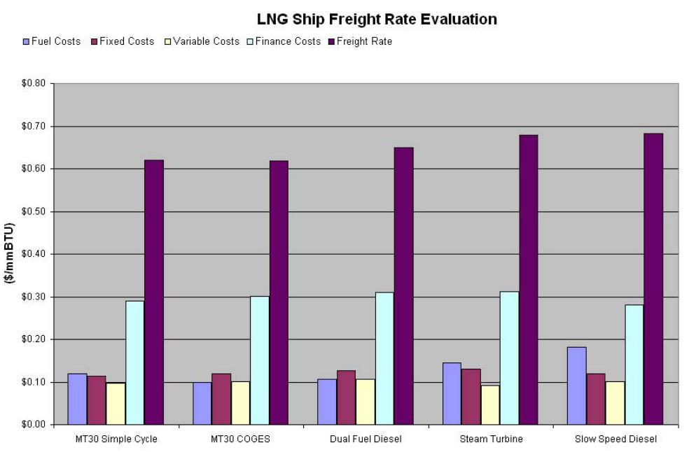
The economic model demonstrates the clear competitive advantage of the MT30 based simple cycle gas turbine and COGES systems against the alternatives. This economic advantage is maintained throughout the range of vessels considered (145 000 m3 to 250 000 m3). Interestingly, the economic advantage predicted for large LNG carriers on long routes is surpassed by “standard” vessels on short routes, which is explained by the “capacity advantage” being used more frequently.
Conclusions
It has been said that the LNG shipping industry is the most reliable and well organised of all shipping operations. Moving this structured industry through a period of expansion and change must not compromise the high standards achieved and indeed should look to reduce freight rates while improving reliability and environmental impact. Through developing relationships with shipyards, ship operators and owners Rolls-Royce have developed a number of innovative LNG carrier propulsion systems based upon the modern MT30 gas turbine that demonstrate the compelling technical and economic advantages for all parties involved.
These advantages can be summarised as follows:
Shipowner/Operator:
- Reduced Freight Rate.
- Improved Reliability.
- Improved Efficiency.
- Lower Capital Cost of Vessel.
- Low Routine Maintenance.
- Environmentally Friendly.
- Reduced Manning.
Shipyard:
- Lower labour costs.
- Shorter Build time.
- Reduced Risk.
In developing the powering solutions for LNG carriers, close attention has been paid to understanding the particular requirements and complexities of an LNG carrier and produce technical solutions for auxiliary systems, such as the gas fuel system, where traditional systems must be up rated.
These generic gas turbine propulsion systems are now fully developed and have been specifically applied to future projects where detailed design work has been undertaken with shipyards.
Outside of the marine shipping sector, the gas turbine has become firmly established as the prime mover of choice for the oil and gas industry, powering facilities and pipelines. The use of a fleet of gas turbines powering pipelines, liquefaction and regasification facilities (electrically driven power station concept), gas distribution and LNG carriers would yield exceptional savings but market complexities would make realisation extremely difficult.
As with the rest of the gas industry, the modern aero- derivative gas turbine is the ideal solution for powering LNG carriers.