This article will talk about different propulsion systems, what can be used on LNG carrier.
The concept of carrying a cryogenic liquid natural gas (LNG) by sea at temperatures of minus 160 °C is both fascinating and challenging. LNG ships have created great interest since the early experimental voyages in the late 1950’s.
- Summary
- Introduction
- A Brief History of LNG Shipping
- What are the Special Requirements of an LNG Carrier?
- Propulsion Alternatives for LNG Carriers
- Future Considerations Patterns for LNGC’s
- What Alternative Arrangements Have Been Tried in the Past?
- Propulsion Alternatives for Liquefied Natural Gas Carriers
- Alternative 1; Slow Speed Diesel with BOG Reliquefaction
- Alternative 2: Dual Fuel Diesel-Electric Propulsion
- Technical Comparison of the Propulsion Alternatives
- Economic Comparison of the Propulsion Alternatives
- Results
- Conclusions
Much of the attention has been on the extremely demanding job of designing a cargo containment system to keep this cold cargo away from the ship’s hull.
Summary
But LNG ships are also unique in that they still adopt steam propulsion – as this is an ideal way to dispose of the cargo vapour that inevitably “boils off” from the cargo tanks.
While steam plant is well proven, of late there have been a number of innovations – especially the development of shipboard reliquefaction systems and medium speed diesels that can burn natural gas as an alternative fuel to oil. These developments offer significant fuel cost savings in future LNG designs, and DML has studies the alternatives. This article will review the technical aspects of the most promising alternative LNG propulsion layouts now available.
Introduction
After a long period of steady expansion, the LNG shipping industry is in a phase of rapid growth. LNG Ships are currently being built at an unprecedented rate to carry the increasing volumes of cargo being produced by LNG liquefaction plants around the world.
LNG has been a commercial cargo for some 40 years now, during which time the trade has expanded “slowly but surely”. Environmental considerations have created increased interest in this “clean & green” fuel, and the awareness of the reduced long-term availability of oil has increased the emphasis on natural gas as a primary energy source.
Furthermore, several major markets – notably the USA and the UK – are also experiencing significant reductions in natural gas availability from “local” sources, and are looking to LNG to make up the shortfall.
LNG shipping has an exemplary record of safety, and the gas industry has always taken a very careful approach to risk management. One area of study has always been ship reliability, because the ships are normally built to provide secure, long-term supplies to Utility Companies – and reliable deliveries are essential.
A key part of ship reliability studies has been the choice of propulsion. In the International trade of Liquefied Natural Gas in maritime industryearly days of the trade, it was natural to adopt steam propulsion. Technical advances elsewhere now mean that alternatives are available that offer similar reliability – if not better.
Dorchester Maritime Ltd (DML) is very actively involved in the crew and technical management of all types of liquefied gas carriers including LPG, Ethylene and LNG ships. Some time ago we started to look seriously at options for LNG designs as part of our studies on the future of this industry. We set out to investigate the alternatives now available to the traditional layouts based on steam propulsion – including the use of cargo reliquefaction.
A Brief History of LNG Shipping
The first commercial cargo of LNG was loaded in Arzew, Algeria and delivered to Canvey Island, UK some 40 years ago.
The trade started after successful initial trials with LNG on a converted WW2 “C1” standard vessel which made several trans-Atlantic crossings from Lake Charles, USA to Canvey Island from 1959. These trails were conducted by an Anglo-American consortium. Similar trials were conducted by a French team in 1961 using a converted “Liberty” ship.
The positive outcome of the LNG trials lead to orders for 2 LNGC’s by British Gas for the UK imports and 1 ship to bring LNG to Spain. These ships entered service in 1964/65 and the French-built vessel is still in operation at the age of 39 years!
The original 3 ships were small by today’s standards – between 27 500 and 29 000 m3 cargo capacity. Incidentally, LNGC’s are usually quoted in “m3 cargo capacity” rather than “deadweight tonnes” because the density of an LNG is very low at about 0,45 mt/m3.
The designers of the original ships faced numerous problems, the most fundamental of which was “what to do with the cargo boil-off”. The Laws of Physics dictate that if the cargo is at about – 160 °C and the ambient temperature is some 180 – 200 °C above that, the result will be some evaporation of the cargo regardless how efficient is the insulation system fitted to the cargo tanks.
It was acceptable for the experimental ships simply to “vent” the cargo boil-off. But this was clearly unacceptable for a commercial ship.
The cargo tanks of the early ships had a relatively large surface-to-volume area because the tanks were quite small. This fact – combined with the quality of the insulation adopted – gave a “boil-off rate” of over 0,3 % per day. This is the measure of insulation efficiency used in the LNG business, and relates to the daily volumetric loss of cargo from the Coupling Between Liquefied Gas and Vessel’s Motion for Partially Filled Tanks Effect on Seakeepingfull tanks on the loaded passage. In other words, a 10 day passage would mean a cargo loss in excess of 3 %. For this reason, a high service speed was adopted – simply to minimise the boil-off losses.
But this boil-off was a potential fuel for the ship. After much discussion with the Class and Regulatory Authorities, safety systems were agreed to permit the burning of the boil-off gas (BOG) in the main machinery of the commercial LNG carriers.
Ships delivered in 1964/65 were obviously designed at the time when about half of the world’s merchant fleet was steam-propelled. So it was no surprise that the LNG pioneers adopted this system. Steam propulsion had the added advantage that the main boilers could be adapted readily to burn either heavy fuel oil or cargo boil-off in virtually any proportion – though for safety the Class rules required a minimum of 10 % oil at all times (to act as a “pilot light” and prevent any furnace explosions with gas). It was also forbidden to manoeuvre on gas, so the “boil off” had to be contained during pilotage or vented in a controlled manner.
The high service speed adopted for the early LNG carriers also enabled the boil-off gas to be burned completely, as the power required for full speed exceeded the energy available from the boil-off. A very elegant solution to the “boil-off” issue.
The development of LNGC’s is well documented, and need not be repeated here. Suffice it to say that within 10 years the LNG business had changed dramatically. Gas discoveries in the North Sea stunted the intended growth of LNG imports to the UK, and the trade had focussed on the Far East. Ship size had increased to 125 000 m3 and the new terminals were built to suit this size of ship. Merchant ships had increasingly adopted diesel propulsion – especially after the bunker price rises of 1973. But LNG remained the exception – steam propulsion was still the “norm”. And so it still is today.
What are the Special Requirements of an LNG Carrier?
Before discussing alternative arrangements, it is essential to review precisely what is required of an LNG carrier. The ship is an essential link in the supply chain, so the emphasis on safe and reliable service is over-riding.
The requirements for an LNGC can be summarised as follows:
- Highest standards of safety;
- Exceptionally high reliability & availability;
- Long service life;
- High service speed;
- Fast turn-around in port.
Until recently, the number of LNG ships was quite modest. Even today – as the recent crop of orders translates into ships delivered – there are only about 170 LNGC’s in service. The relative rarity of LNGC’s is a marked contrast to all other types of tankers – including LPG carriers. This led to another distinctive aspect of the LNG industry, namely to build ships for specific projects and dedicated routes. The project could not operate without the ships, hence the emphasis on reliability.
This “link-in-the-chain” perspective on LNGC’s also highlights another fundamental difference between LNGC’s and more conventional ships. Namely that if a normal ship has a breakdown for say 24 hours, the penalty is one day “off hire” at the daily charter rate of the ship. With an LNGC, any outage during service could mean that the exporting liquefaction plant may have to shut down if there was no storage available for LNG production until the next ship arrived. So the “out of service” cost of an LNGC was calculated as an “opportunity loss” for the LNG production plant rather than in terms of ship charter hire.
Read also: Condition Assessment Program for Liquefied Gas Carriers (CAP LNG)
The final point to recognise when considering LNGC’s is that for many years these ships had a very unusual double-hull construction. Which made them relatively expensive from the outset. For example, in 1973 a “standard” VLCC cost some 7 M US $ compared with the 50 M US $ quoted for an LNGC at that time. A factor of 7:1. Whereas now the VLCC:LNGC cost ratio is nearer 2:1.
Propulsion Alternatives for LNG Carriers
The steam system design seen in modern LNGC’s is very similar in outline to the layout on the early ships. The plant usually comprises two boilers supplying steam to the high and low pressure turbines, which in turn drive a single screw via a gearbox. Electrical power is typically provided by two steam turbo-alternators and one diesel genset.
This arrangement is a proven means of propulsion for gas carriers. Its advantages are low maintenance and practically non-existent lubricating costs, plus the ability to burn HFO and BOG in any proportion. Furthermore, the steam plant offers an easy method to dispose of excess BOG – by burning it to raise steam, which is then condensed.
The major drawbacks of the steam system are the low efficiency of the turbine plant with the inevitable high fuel costs and consequent excessive CO2 emissions. The space required for the engine room is larger than for a motor ship, and the layout offers very limited propulsion redundancy.
A further drawback is the long delivery time for turbines and the very limited production versus demand. This can cause major problems due to “off hire” and delays in case of a turbine or gearbox failure when the ship is in service.
It is hardly surprising that the LNG industry has been slow to move from steam propulsion, given the background outlined above. Reliable deliveries are of paramount importance, and steam propulsion has been regarded as more reliable than diesel machinery. However this perception has been disturbed by recent well-publicised gearbox failures and the realisation that major spare parts for turbine systems are not available “off the shelf”.
Two recent developments offer the prospect of change for LNG designs. First is the development of high-efficiency medium-speed diesels that can run on gas or oil – and that can change between fuels while running.
Second is the experimental LNG reliquefaction plant fitted aboard a Japanese ship “LNG JAMAL” – which is reported to operate to the design criteria after some minor “teething troubles”. It is important to understand that the low thermal efficiency of steam systems precludes the economic use of cargo boil-off reliquefaction on existing LNGC’s; it would simply cost too much fuel to generate the electricity needed to run this plant.
Future Considerations Patterns for LNGC’s
Today, most LNGC’s are still fixed to specific long-term “projects”. However the “short term trade” in LNG is increasing – which is another commercial reason to review propulsion alternatives.
Short term trading totals only about 5 – 10 % of LNG transportation at the moment. However, when viewed in the longer term, this proportion is likely to increase.
The increase in short term LNG trades – often involving single voyages – will mean that future LNG ship designs will have to offer greater flexibility. Furthermore, several of the new projects under discussion involve “offshore” facilities. Steamships have very limited manoeuvring characteristics – especially in the “astern” mode. This limitation will pose problems if existing LNGC’s are asked to load or discharge at these planned “offshore” facilities.
Future requirements regarding safety and the environment are likely to become stricter. Which means we must also look to an ecologically friendly propulsion installation with minimised emissions. Furthermore, the future propulsion systems for LNGC’s must be of a proven, easy-to-operate design. The shortage of experienced steam engineers is already a concern, together with the diminishing range of opportunities for steam training. The range of makers & suppliers of steam equipment has also diminished rapidly over recent years – which must be of concern to operators who are looking to a 40 year life for their LNGC’s.
We can foresee that in the future, propulsion systems will have to offer:
- Improved efficiency;
- Increased redundancy;
- More familiar machinery to ensure the availability of trained staff;
- Improved availability of spare parts & service support;
- Better manoeunvrability;
- Reduced engine room dimensions.
What Alternative Arrangements Have Been Tried in the Past?
Before we look into the future, we should always look back and see if anyone has tried any alternatives in the past. It should come as no surprise that most of the options we are looking into today have been tried at various times in the past.
It is instructive to look into the experiences.
- Slow-speed diesel propulsion with high-pressure gas injection. One of the early prototype Moss spherical LNGC’s (capacity 29 000 m3) was equipped to burn boil-off in the main engine, a 7RND90 Sulzer machine. For most of its trading life, the ship did not carry LNG but was in the LPG business. So the high-pressure injection system was taken out of Class and de-commissioned.
- Gas turbines burning boil-off. A second prototype Moss ship (also 29 000 m3 capacity) was fitted with a GE MM5212R gas turbine designed to burn oil or natural gas. Again this ship did not carry LNG, and it is understood the gas turbine received unsuitable oil fuel – which caused major deterioration to the combustion system and the exhaust heat recovery exchanger. The system was beyond economic repair; so the Owners fitted a 7RND90 Sulzer engine – but without gas burning facilities as again the ship was in the LPG trades.
- At least one small ship of 2 500 m3 capacity was built for a short-sea LNG trade in the Mediterranean which did not materialise. The ship had a medium- speed MWM main engine, which was converted specially to burn oil or natural gas. The trails on gas were reported as partially successful, but the Owners did not proceed further as the ship was re-Classed as an Ethylene carrier and the gas-burning facilities were removed.
- An Algerian ship of about 125 000 m3 capacity was retro-fitted with a boil-off reliquefaction plant that could recondense part of the daily cargo evaporation losses. The plant was reported to work successfully, but the extra cost of fuel to operate it outweighed the value of the gas recovered. So the experiment was abandoned for economic reasons. It is understood that the plant aboard LNG JAMAL has also been “mothballed” for the same reasons.
Propulsion Alternatives for Liquefied Natural Gas Carriers
A variety of propulsion alternatives are available, notably:
- Slow speed diesel burning HFO with BOG reliquefaction;
- Dual fuel diesel-electric propulsion;
- Combined cycle (gas turbine + steam) electric propulsion;
- Slow speed diesel burning high-pressure BOG.
The authors have limited the detailed evaluation to the first two systems as being the most immediate options. However, we are continuing to evaluate gas turbine installations for specific cases, and the alternative of high-pressure gas injection to a slow-speed diesel. The latter offers the possibility of cheap alternative fuel, namely HFO, but much of the advantage in fuel economy is lost by the power required to compress the gas up to pressures suitable for injection systems.
Alternative 1; Slow Speed Diesel with BOG Reliquefaction
Most merchant ships today are driven by a single diesel engine; this is a proven and highly reliable propulsion system. Major advantages of the diesel system are the high overall fuel efficiency – which is about 60 % higher than for steam plants, the reduced engine room space required and considerable lower initial costs.
Diesel propulsion is perceived as offering less redundancy than existing steam systems, which we do not completely accept. In any case, redundancy could be achieved by installing a combined power take off, power take in (PTO/PTI). In the case of a main engine failure, the e-motor on the shaft line would be driven by the diesel gensets, which would allow the ship to sail at a safe manoeuvring speed. This is a proven design which has been installed on several shuttle tankers.
Another consideration with diesel propulsion is that amount of LNG delivered is higher because the BOG is being reliquefied. One negative point is the potential increase in NOx, and SOx emissions as the engines burn HFO; however the amount of CO2 released into the atmosphere could be reduced by approximately 100 000 mt/ship/year compared to a steam ship.
For our analysis, the system shown in Pic. 1 was adopted.
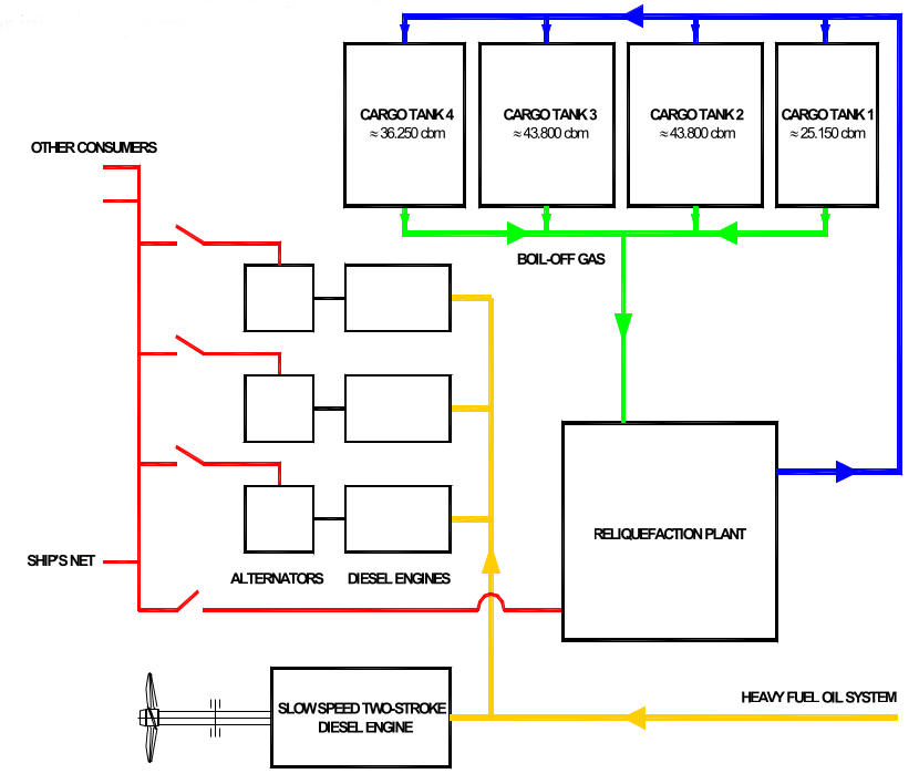
The Birth of the Reliquefaction, Design and Operation of the Reliquefaction LPG Plantreliquefaction plant is a closed Brayton cycle. The BOG is removed from the tanks, compressed and cooled and condensed to LNG in a cryogenic heat exchanger. Non-condensibles, mainly nitrogen, are removed in a separator and exited to the vent. The LNG is returned to the tanks. The cryogenic temperature in the heat exchanger is produced by means of a nitrogen compression – expansion cycle. The plant requires about 3,5 MW electrical power.
Alternative 2: Dual Fuel Diesel-Electric Propulsion
The second propulsion alternative is the dual fuel diesel electric system. The dual fuel engine is basically a normal 4-stroke diesel which can utilise natural gas as fuel. The gas is injected into the air intake and a small amount of diesel is added in the combustion chamber to ignite the gas/air mixture. The engine is also capable of only running on MDO, switching from gas to diesel mode is possible within one revolution of the engine.
The system is extremely environment friendly. When using LNG as fuel there is very little NOx, no SOx and no particle emissions. The reduction of CO2 emissions totals approximately 100 000 mt per year compared to a standard steam-driven LNG carrier.
The diagram of the system is shown in Pic. 2.
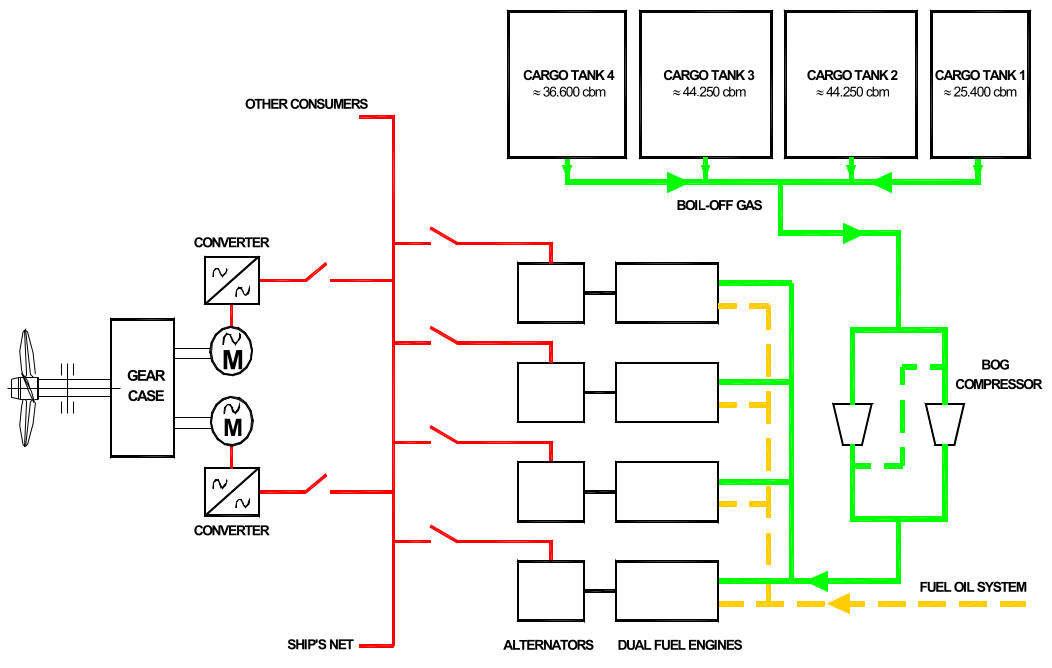
Four diesels provide electrical power for the main propulsion motors and the other electrical consumers. This gives a high flexibility between different operating modes. The total power installed is less than for any other propulsion alternative because of this flexibility.
As the diesels are producing electricity, an in-line arrangement of shaft/gearbox/engine is not necessary. So the diesels can be arranged on a higher deck, thus reducing engine room space demand. The layout offers multiple redundancy, apart from the shafting and the gearbox. Even in the event that two diesels should fail, or one electric motor is out of use, the ship would be able to sail at about 75 % of its design speed. An LNGC of about 145,00 m3 with diesel-electric propulsion will be able to take about 5 000 m3 more cargo than a steam-driven ship with same overall dimensions.
The main disadvantages of this system compared to the alternatives are the slightly higher initial costs and the small efficiency loss in the power generation process.
Technical Comparison of the Propulsion Alternatives
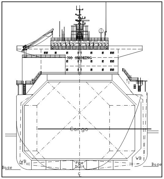
A state-of-the-art 145 000 m3 LNG carrier, with main particulars as shown in picture 4. was used as the basis for the technical and economical evaluation.
Picture 3 shows the predicted power requirements, efficiency figures and initial costs of the different propulsion options.
The difference in required power is merely due to different efficiency losses between the propeller and the engine or turbine. Since the diesel- electric version is producing electrical power, the loss of efficiency is greater than for the mechanically driven propeller.
| Comparison of Propulsion Efficiency Figures | |||||
|---|---|---|---|---|---|
| Steam Turbine (Single Screw) | DF Diesel Electric (Single Screw) | 2-Stroke Diesel Engine (Single Screw) | |||
| Fuel/Boil-off Gas | 1,00 | Fuel/Boil-off Gas | 1,00 | Fuel | 1,00 |
| Boiler | 0,88 | DF-Diesel Engines | 0,46 In gas mode 0,48x | 2 Stroke Engine | 0,49 |
| Steam Turbine | 0,35 | Alternators | 0,97 | Shafting | 0,99 |
| Gearbox | 0,98 | Converters | 0,98 | ||
| Shafting | 0,99 | E-Motors | 0,96 | ||
| Gearbox | 0,98 | ||||
| Shafting | 0,99 | ||||
| Total Efficiency | 0,30 | Total Efficiency | 0,41 In gas mode 0,43x | Total Efficiency | 0,48 |
We also considered the changes in cost for the different propulsion systems, both in terms of equipment purchase cost and shipyard installation.
The result was an estimate that a dual-fuel diesel electric ship would cost 4,1 M US $ more to build than a conventional steam ship, while an HFO-burning slow-speed diesel ship with reliquefaction plant would cost some 5 M US $ less than a conventional (steam) LNGC.
Pic. 4 shows the different cargo capacities than can be achieved with the various propulsion alternatives, while maintaining the same main ship particulars. These additional volumes are considered to be very conservative, but it could also be argued that the project could simply lengthen a steam ship at modest cost if more capacity was required.
Economic Comparison of the Propulsion Alternatives
The following five options were compared:
- “Benchmark” ship: steam propulsion using natural BOG and HFO for propulsion;
- Slow speed diesel with BOG reliquefaction;
- Diesel-electric completely fired by LNG (natural BOG and forced BOG);
- Diesel-electric fired by natural BOG and additional MDO;
- Diesel-electric HFO fired with BOG reliquefaction.
The options were calculated for 3 different trades:
- Arabian Gulf to Boston:
- 345 sea days, 20 port days, 36 sailing days.
- Trans-Atlantic:
- 328 sea days, 37 port days, 18 sailing days.
- Trans-Caribbean:
- 279 sea days, 86 port days, 6,5 sailing days.
The economic assumptions are as follows:
- “Benchmark” ship contract price: 185 M US $;
- The costs for different propulsion systems as shown earlier were taken into account;
- Financing over 20 years at 7,5 % interest rate;
- BOG-reliquefaction system (redundant) 6 M US $ extra investment and 3 500 kW extra power;
- Additional maintenance & lubrication cost for DE and slow speed diesel included;
- The costs difference of the various propulsions systems shown above included.
Further economic basis were:
* Efficiencies:
- Steam: 0,30;
- Diesel electric: 0,41 (on MDO)/0,43 (burning gas) 2-stroke-Diesel: 0,48.
* Fuel Price:
- HFO: 185,50 USD/t;
- MDO: 380,00 USD/t;
- LNG (FOB): 104,00 USD/t (2 USD/mmbtu);
- LNG (CIF): 156,0 USD/t (3 USD/mmbtu).
* Lower heating values:
- HFO: 40,4 MJ/kg;
- MDO: 41,8 MJ/kg;
- LNG: 49,2 MJ/kg.
The fuel prices used are initial values. To allow for future fuel price increases we assumed that the HFO and MDO prices increase in linear fashion to the LNG CIF price. The LNG FOB price was assumed to increase by only 50 % of the CIF price increase.
Results
Pic. 5 shows fuel costs as a percentage compared to the “benchmark” steam-powered LNG ship, which represent 100 %.
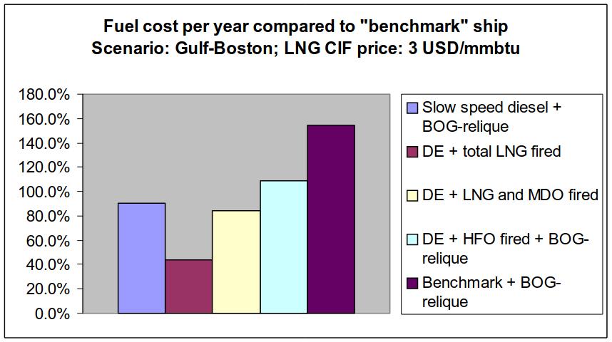
The fuel costs are shown for current fuel prices for the Gulf to Boston trade. Although the slow speed diesel with BOG reliquefaction has the best efficiency, it is evident from the graph that the propulsion options burning LNG have greater cost savings. The higher heat values and lower fuel prices of the LNG overcompensate the slightly lower efficiency.
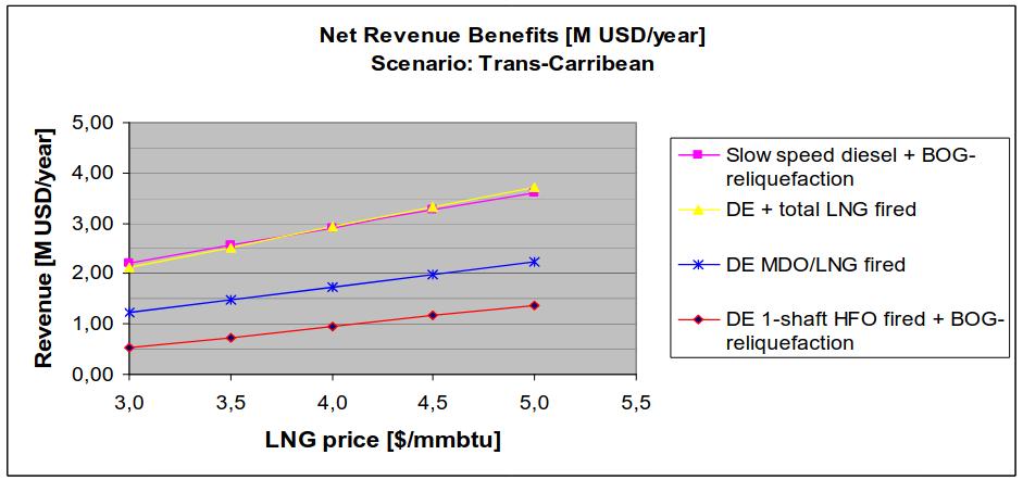
The net revenue in M USD/year for increasing LNG prices is shown in pictures 6 to 8 for the different trade scenarios. The X-axis, or zero (0) revenue presents the benchmark ship.

It is clear that all options achieve considerable revenue with increased benefits for rising LNG prices. Longer trades also allow higher savings.
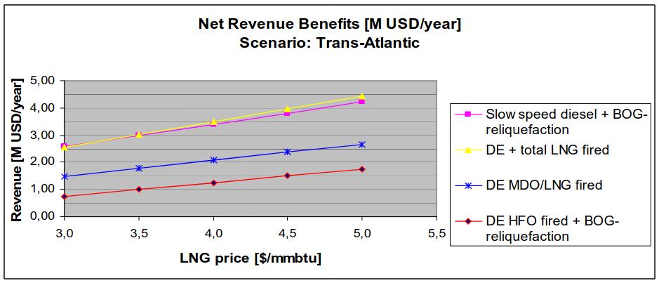
At current LNG and fuel prices the max. achievable annual revenue benefit for the Gulf to Boston trade totals abt. 2,8 M USD for the slow speed diesel with BOG reliquefaction as well as for the diesel electric version utilising only LNG as fuel.
One remarkable result is that the benefits can still be achieved with the diesel electric version firing HFO, considering the lower heat value & higher price of HFO as well as the additional investment and power consumption of the reliquefaction plant.
This result demonstrates that a reliquefaction plant can be a viable option even for the diesel electric version, not only if HFO is the fuel, but also for dual fuel engines burning LNG, especially when involved in the spot cargo trade. The spot market will make it essential for vessels to be flexible and to operate efficiently at varying speeds, which will be encountered on different routes.
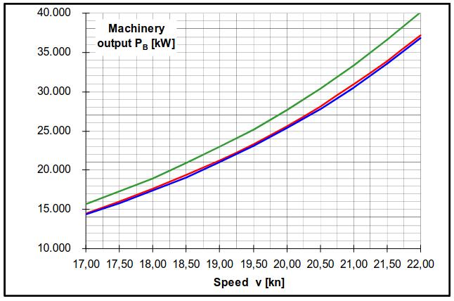
Picture 9 gives an example for the viability of the reliquefaction system. The curve shows the LNG consumption for the diesel-electric version for the given speed.
The boil-off-rate is more or less constant at 0,15 %/day which is about. 100 mt/day for a 142 000 m3 ship. The shaded area above the curve indicates excessive boil off. If, for example, the ship was on a trade where it has to sail at only 18,0 knots, then 25 t of excessive boil off would be lost every day without a reliquefaction plant. The slower the sailing speed the more beneficial a reliquefaction plant can become. Additionally a reliquefaction plant makes the ship more flexible regarding the choice of fuel in the future in the case of non-linear fuel price increases.
Conclusions
The evaluation has shown that there are clear arguments to move forward from steam propulsion for LNG ships. The slow speed diesel and the dual fuel diesel-electric are equivalent in terms of economic benefits. They both offer higher redundancy, increased flexibility as well as greater cargo capacity than steam ships. Installation of a cargo reliquefaction plant also offers a promising solution for current and future demands on LNG’s.
New LNG ship designs must look at propulsion alternatives, especially considering the reduced emissions of NOx, SOx and CO2 together with future trading patterns and fuel choice flexibility.