Safety System integration is crucial for ensuring the safe operation of LNG (Liquefied Natural Gas) facilities. A well-designed safety system can help prevent accidents, safeguard personnel and protect the environment. Safety system components must be seamlessly integrated to provide comprehensive monitoring and control capabilities. This integration ensures that all systems, including alarms, sensors and communication devices, function cohesively, contributing to the overall safety of LNG operations. The Safety system should be continuously tested and updated to adapt to new challenges and adhere to evolving industry standards.
- Nitrogen Control System
- General Cosideration
- Control System
- Gas Detection System
- Infrared Gas Analyser System – Cargo Area Locations
- Catalytic Combustion Analyzer System
- Gas Detection System General Arrangement
- Fire Detection System
- General Feature
- Central Unit Panel
- Led Indicators
- Fire Alarm
- Prewarning
- Water Detection System in Interbarrier Space
Furthermore, compliance with safety system regulations is paramount for LNG operations. Regulatory bodies require that safety systems are robust, ensuring that they can withstand various pressures and hazards associated with LNG. Regular audits and inspections are conducted to verify that the safety system meets all necessary standards and guidelines. Stakeholders must collaborate to ensure that the safety system is not only compliant but also contributes to enhancing safety culture within the company. This commitment to a robust safety system elevates safety standards, reduces risk and ultimately prevents costly incidents in the LNG industry.
Nitrogen Control System
General Cosideration
The nitrogen is produced by a nitrogen generator supplying a buffer tank. The nitrogen is then supplied to the primary and secondary barrier. The nitrogen is supplied at the liquid dome and exhaust at the gas dome.
Low and high-pressure alarms are provided for the both barriers. There is also an alarm for the barrier differential pressure. In normal operation the barrier pressure is set and the inlet and exhaust valves are controlled to keep the set pressure. As ultimate safety measure, each barrier spaces is fitted with two pressure relief valves.
Control System
A typical control panel permits fully automated unmanned operation of the units. The following alarms and controls are mounted on the control panels:
- Pushbuttons for start/stop operation.
- System status indications.
- Pushbutton for audible alarm acknowledgement.
- Continuous N2 delivery pressure.
- Continuous O2 content reading.
- Dew point analyzer.
- Electrical heater temperature control.
- Emergency stop pushbutton.
Gas Detection System
There are typically two independent gas detection systems installed on Rules and Regulations for LNGCLNGC’s, which cover the cargo, machinery and accommodation areas (Alarm indication is shown in the CACC on the IAS system):
- Infra-red gas analyzing.
- Catalytic combustion analyzing.
Infrared Gas Analyser System – Cargo Area Locations
This type of system is used primarily in the cargo and boiler burner hood areas. In the cargo area, the primary and secondary insulation spaces and vent masts of each Independent Cargo Tankscargo tank have sampling points.
Additionally, the port & starboard side passageways, duct keel, cargo compressor room, motor room and escape trunk are all monitored.
In the machinery space, the P/S boiler double-walled boil-off gas pipe, engine room vent fans ducting, boil-off gas room (burner hood), and inert gas line after the dryers are included in the coverage.
The analyzer works on the principle the infra-red light is absorbed by methane gas. Samples are drawn past an analyzer and compared with reference sample of air. Except the primary insulation space(s), if a sample reaches 30 % LEL then an audible alarm is sounded. For the primary insulation space(s) the concentration must reach 30 % of volume before an audible is sounded.
Points which are related to ventilation, such as the side passageways, are monitored up to 60 % LEL. At that point, the ventilation fan involved will be stopped and indication thereof given.
The boil-off gas piping in way of double wall space is monitored continuously by its own separate sampling analyzer. At 30 % LEL, an audible alarm is sounded and at 60 % LEL, the Master Gas Fuel Valve is closed.
Catalytic Combustion Analyzer System
This type of system continuously monitors the atmosphere in the vicinity of the sensing heads.
The sensing heads are fitted in areas where gas, if leaked, would be likely to accumulate.
The heads generate an electrical signal, directly proportional to the amount of gas present, to alarm and indicating units in the W/H, CCR, ECR, and FCR. Spaces monitored include:
- Bosun stores, BT room, Forward Pump Room.
- EDG room, Incinerator room, ECR, ER 1st deck.
- W/h, CCR, Lift space, Accomodation entrances, Crew & Officers’ Rec.rooms, Galley, Fresh Air Inlet to A/C, Cargo SB room, Conference Rm, and Ship’s office.
- All of the above alarm at 30 % LEL, exc. A/C, which alarms at 60 % LEL and shuts fan(s) down.
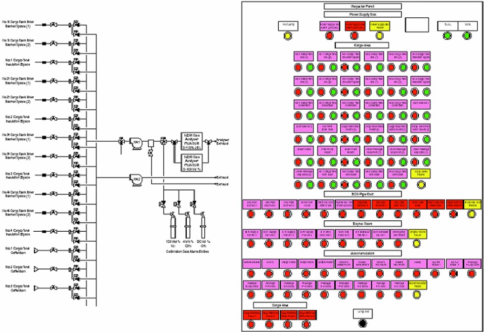
Gas Detection System General Arrangement
Figure 1 shows a typical arrangement of gas detection system diagram and control panel.
Fire Detection System
General Feature
The fire detection system is a complete fire detection and alarm system, including combined fire alarm and operating panels, control units and power supply units, all contained in single cabinets. The master panel is fitted on the bridge with three remote repeater panels included in the system. These are fitted in the CACC room, ECR and fire control station. Fire and smoke detectors and manual call points are connected to the system in loop configurations.
There are a wide range of fire detectors and sensors fitted to suit different requirements and conditions, such as smoke, heat and flames, watertight, non-watertight and explosion proof detectors. Manual call points, short circuit isolators and timers are connected to the loop where required. A fault in the system or a false alarm is detected immediately, since the function of the detectors and other installed loop units are automatically and continuously tested. The relay outputs of the system can be used to control doors and ventilation systems.The fire alarm indications and alarm are activated when there is a fire alarm on the system.
Central Unit Panel
The operator verifies and supervises the system by using the different keys and the display on the operating panel.The operating panel consists of a text display information window, indication lamps, operating buttons and numerical keypad. These control items enable the entire fire detection and alarm system to be controlled. See Figure 2 for a typical example.
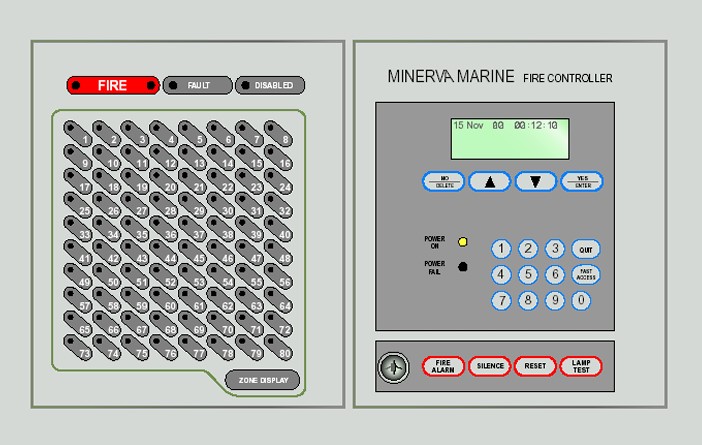
Led Indicators
- POWER ON: Indicates the presence of system electrical power.
- POWER FAIL: Indicates the failure of all system electrical power.
- FIRE: Indicates the presence of a fire condition.
- FAULT: Indicates the presence of a fire condition.
- DISABLED: Indicates the disabling of a circuit/detector (eg, isolation).
- FIRE ZONES: Indicate an alarm in the relevant zone.
Fire Alarm
The following indications appear on the control panel in the event of a fire alarm:
- The red FIRE indication LED’s flash and the alarm sounds.
- The red ZONE(S) indication LED’s flash.
- The text display indicates the address(es) of the detector(s), which initiated the first fire alarm.
- All sounders/fire doors/alarms/fan stops are activated (as connected – programmed).
Prewarning
In certain conditions, such as a rise in the detector ionization level, a detector may trigger a pre-warning alarm. This may be a prelude to an actual fire alarm as smoke may be building up but the level has not reached the alarm threshold, so the alarm should be thoroughly investigated.
- The following indications appear on the display in the event of a pre-warning.
- The text display indicates the address(es) of the detector(s), which are in the in pre-warning mode.
- The internal buzzer sounds.
- The event is logged and must be accepted.
If the detector, which activated the pre-warning event, subsequently goes into alarm, then a full alarm is raised regardless of whether or not the pre-warning event has been acknowledged.
Water Detection System in Interbarrier Space
At the bottom of each cofferdam there are two bilge wells serving the forward and aft ends of each Best Practices for Gas Tank Installation and Cargo Tank Insulationtank insulating space. Each of these wells is fitted with two water detection units, one working and one spare.
Each detector is of the conductivity cell type, which causes a change in resistance due to the presence of humidity from ingress of seawater and activates an alarm. The tank insulation space is connected to each of the fore and aft bilge wells by means of a 150 mm drain pipe. The aft bilge well serves as the inlet for the nitrogen 50 mm supply pipe to the insulation space. This supply pipe also acts as a manual sounding pipe to the bilge well.
The forward bilge well has a manual 50 mm sounding pipe, which can also be connected to a portable liquid level gauge (bubbling type) and also serves as a gas sample line.

- The Society of International Gas Tanker and Terminal Operators (SIGTTO). Liquefied Gas Handling Principles on Ships and in Terminals (LGHP4) / 4th Edition: 2021.
- The international group of liquefied natural gas importers (GIIGNL). LNG custody transfer handbook / 6th Edition: 2020-2021.
- American Gas Association, Gas Supply Review, 5 (February 1977).
- ©Witherby Publishing Group Ltd. LNG Shipping Knowledge / 3rd Edition: 2008-2020.
- CBS Publishers & Distributors Pvt Ltd. Design of LPG and LNG Jetties with Navigation and Risk Analysis / 4th Edition.
- NATURAL GAS PROCESSING & ITS ENERGY TRANSITION ROLE: LNG, CNG, LPG & NGL Paperback – Large Print, November 14, 2023.
- American Gas Association, Gas Supply Review, 5 (February 1977).
- The Society of International Gas Tanker and Terminal Operators (SIGTTO). Ship/Shore Interface / 1st Edition, 2018.
- Department of Transportation, US Coast Guard, Liquefied Natural Gas, Views and Practices Policy and Safety, p. IV-3.
- Department of Transportation, US Coast Guard, Liquefied Natural Gas, Views and Practices Policy and Safety, p. IV-4.
- Federal Power commission, Trunkline LNG Company et al., Opinion No. 796-A, Docket No s. CP74-138-140 (Washington, D. C.: Federal Power Commission, June 30, 1977).
- Federal Power Commission, Final Environmental Impact Statement Calcasieu LNG Project Trunkline LNG Company Docket No. CP74-138 et al., (Washington, D. C.: Federal Power Commission, September 1976).
- Federal Power Commission, «FPC Judge Approves Importation of Indonesia LNG».
- OCIMF, ICS, SIGTTO & CDI. Ship to Ship Transfer Guide for Petroleum, Chemicals and Liquefied Gases / 1st Edition, 2013.
- Federal Power Commission, «Table of LNG imports and exports for 1976», News Release, June 3, 1977, and Federal Energy Administration, Monthly Energy Review, March 1977.
- Office of Technology Assessment LNG panel meeting, Washington, D. C., June 23, 1977.
- Socio-Economic Systems, Inc., Environmental Impact Report for the Proposed Oxnard LNG Facilities, Safety, Appendix B (Los Angeles, Ca.: Socio-Economic Systems, 1976).
- «LNG Scorecard», Pipeline and Gas Journal 203 (June 1976): 20.
- Dean Hale, «Cold Winter Spurs LNG Activity»: 30.