Search and Rescue Transponders (SARTs) are critical safety devices used in maritime emergencies to aid in the location of distressed vessels or individuals. A key factor in the reliable operation of a SART is its power supply.
- Search and Rescue Transponders
- Positioning of the SART
- SART Operatiion
- Location Distances
- Power Supplies
- Maintenance Free Batteries
- Lead Acid Batteries
- Battery Construction (courtesy of Battery Council International)
- Battery Connection
- Battery Hazards
- Essential Battery Maintenance
- Battery Cleanliness
- Electrolyte Level
- Correct Charging
- Measuring the Specific Gravity
- Measuring the On-Load Terminal Voltage
- Loss of Capacity
- Connection of Batteries During Emergencies
This article delves into the various aspects of SART power supplies, including the different types of batteries used, their construction, maintenance requirements, and safety considerations. Understanding these elements is essential for ensuring that SARTs function effectively when needed most.
Search and Rescue Transponders
A Search and Rescue Transponder, or SART, is a battery-powered portable device, which may be used by a survival craft to indicate its position to searching aircraft and vessels.
The SART operates in the 9,3 to 9,5 GHz band and will respond only to radar equipment operating on those frequencies (X band, 3 Centimetre radar). The SART will not respond to 3 GHz (S band, 10 Centimetre) radar. The SART should operate in the standby mode for a minimum of 96 hours with a further eight hours of transmission once activated.
Positioning of the SART
Under no circumstances should the SART be placed in the water. The SART should be mounted at least one metre above the water line. When in the survival craft, survivors should position the SART as high as possible with the aid of an oar or the lifeboat mast. Some manufacturers will supply the SART – Search and Rescue Transponders – Portable VHF TransceiversSART with a short telescopic type mast of approximately one metre in length.
SART Operatiion
Once switched on the SART will scan the X band of radar frequencies. When a searching radar is detected, the SART will lock onto that particular radar frequency and commence to transmit on the entire X band, thus enabling all vessels in the vicinity to receive an indication of the SART transmission.
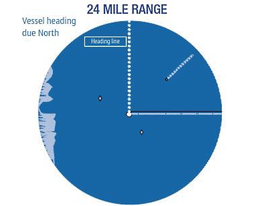
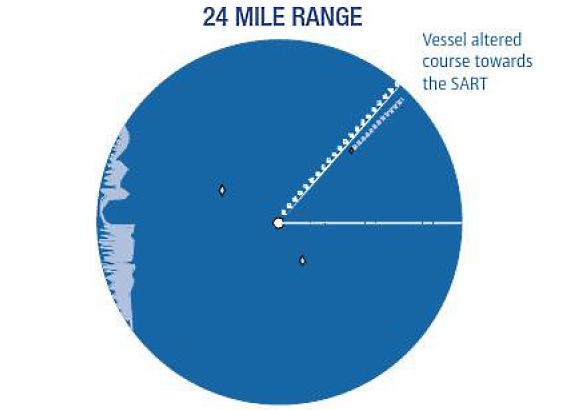
On detecting signals from distant radar equipment, an activated SART will generate a series of response signals of twelve blips which will be displayed on the receiving radar screen, extending in a line, approx 5 to 8 nautical miles in length, outward from the SART position, along its line of bearing. This unique radar signal is easily recognised and the rescue vessel or aircraft can locate the survivors. (See Fig. 1 & 2).
An interrogated SART will provide proof to survivors that it is operating, by means of an audible and/or visible flashing light.
Location Distances
A SART should respond to a ship’s radar with a scanner height of 15 metres at a distance of at least 5 nautical miles.
Read also: Satellite Technology Advances: Electric Propulsion and Launch Platforms
Once locked on to a searching radar there will be a slight delay in the changeover from the SART’s standby or receive mode to transmit mode. This slight delay may cause a small position error of up to 150 metres on the radar screen of the blip associated with the position of the SART. Subsequent radar sweeps will confirm the actual location of the SART.
Power Supplies
Maintenance Free Batteries
Maintenance free lead-acid or gel type batteries are becoming increasingly more popular and available to mariners. Users of these types of batteries are recommended to follow the manufacturer’s guidelines in ascertaining the condition of the battery regarding replacement. On vessels where it is mandatory to carry an List of the Emergency Situations which can happen on the Liquefied Gas Carrierindependent emergency means of electrical supply, for communications equipment, it may also be a requirement to replace maintenance free batteries after a short operational period of 1 year.
Lead Acid Batteries
Many marine batteries used on boats are still of the lead-acid variety. Lead-acid cells consist of a combination of lead and lead peroxide plates. These plates are kept in a solution of sulphuric acid and water (the electrolyte) which produces a potential difference between the plates, and current can flow when a load, such as a Marine VHF Radio – Communication and Emergencymarine radio, is connected. During this “discharge” cycle, the sulphuric acid or the material in the plates is used up. The potential difference no longer exists and current can no longer flow. This process is reversed by passing a current through the cell in the opposite direction and this is known as “charging“.
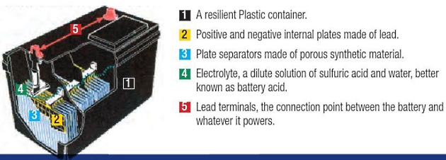
Battery Construction (courtesy of Battery Council International)
Batteries are made of five basic components:
Cell Voltage
Each lead-acid cell has a nominal voltage of 2 volts. A physically larger cell does not supply a higher voltage (Volts).
Cells in a battery are combined to give a total battery voltage, i. e. three cells to produce a 6 volt battery, or six cells to produce a 12 volt battery. Each cell will have a filler cap to enable topping up of the electrolyte by distilled or demineralised water. Three filler caps indicate a 6 volt battery.
Cell Capacity
Electrical current is measured in amperes (amps). Each lead-acid battery has the capacity to supply an amount of current over a specific time and this is known as its Ampere Hour Capacity (AHC). A large cell has the ability to provide a higher AHC over a short period of time or a low current over a longer period of time. Manufacturers will specify the AHC of an individual battery type.
Battery Connection
Batteries can be connected to each other, in order to provide a total operating voltage.
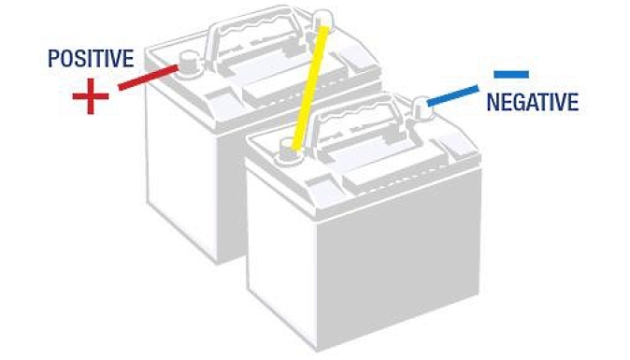
SERIES connections where the negative terminal of one battery is connected to the positive terminal of another battery, i. e. two 6 volt batteries of equal AHC connected together in order to produce a 12 volt operating voltage with an AHC of each battery.
PARALLEL connections, whereby all the positive terminals, of a bank of batteries, are connected together, and all the negative terminals are connected together. In the following Figure two 6 volt batteries with equal AHC connected together in parallel will produce a total of 6 volts with an AHC of the sum of the AHC of each battery, therefore following a longer period overall for the current to flow.
Battery Hazards
There are two hazards associated with lead-acid batteries that ship station operators should be aware of:
- the risk of explosion; and
- the risk of chemical burns.
As a result of the chemical process occurring within the cells of a battery during charging, Hydrogen gas is produced. When mixed with air, this can form a highly explosive mixture which can be ignited by a naked flame, a lighted cigarette, or a spark.
The spark caused by making or breaking an electrical connection in the vicinity of the charging battery may be sufficient to ignite the hydrogen-air mixture. Batteries should be located as close to the radio equipment as possible, and placed in a well-ventilated container or locker. If using metal tools to work on battery connections, extreme care must be taken to ensure that terminals are not short-circuited.
The electrolyte in battery cells consists of a mixture of waler and Sulphuric acid. It is sufficiently concentrated, particularly after charging, to damage eyes, skin or clothes if spilt or splashed. Immediate and prolonged application of running water is recommended to minimise its effect.
It is recommended that eye protection, gloves, etc. be worn when carrying out maintenance on batteries. Batteries should not be topped-up whilst on charge.
Essential Battery Maintenance
The functioning of Inmarsat-A: Equipment, Procedures, and Distress Communicationradio equipment is dependent on power supplied by the battery. If it is to provide adequate performance in the event of an emergency, regular and careful maintenance is required.
A battery’s service life also depends on the manner in which it is treated. To ensure the best performance from a battery it is important that a battery:
- is kept clean, dry and free from terminal corrosion;
- has the electrolyte kept at the correct level; and
- is kept correctly charged.
Battery Cleanliness
A battery top should be kept clean. A dirty battery top may hold spilt electrolyte on its surface, thereby providing a path for the electrical current to leak away. It is important to keep the outside surfaces of a battery dry and free of contamination.
Corrosion forming on terminal clamps may seriously affect, or even prevent, the ability of the battery to supply current. Corrosion will be evident by the formation of a white-green powder between the battery terminals and the terminal clamps. In this situation, the terminal clamp should be removed and both it and the terminal post cleaned.
To minimise the likelihood of corrosion, terminal posts and clamps should be lightly smeared with Vaseline™ or petroleum jelly. A battery which is nearly flat, is defective or has corrosion of on its terminals may be able to provide sufficient current to operate the receiver, but not the transmitter. Should the transmitter fail to operate and the dial lights or channel display lights dim significantly when the transmit button is operated, the battery should be suspected.
Electrolyte Level
The level of electrolyte inside a battery is important. As a result of the chemical action inside a battery, water is lost.
This should be replaced with distilled or demineralised water. Seawater must not be used under any circumstances. The level of the electrolyte should be maintained at approximately 10 mm above the plates unless otherwise specified by the manufacturer. If the electrolyte level is too high, it may overflow during charging providing an unwanted discharge path. If the electrolyte is too low, the plates are exposed to the air and permanent damage and loss of capacity may result.
It may be noticed that a battery that is nearing the end of its useful life will require more frequent topping-up than has been previously necessary. Low-maintenance batteries will require infrequent topping-up. Maintenance-free batteries may require none at all.
Correct Charging
To provide the best service, a battery must be correctly charged. Both overcharging and undercharging can seriously affect its performance.
On small vessels, the usual means of charging the radio battery will be an alternator or generator attached to the vessel’s engine. An associated regulator, which reduces the charging current as necessary, should prevent overcharging.
Vessels that are used frequently (say, several times each week) should have no problem maintaining a fully charged radio battery. However, on vessels that are used relatively infrequently (say, once every few weeks), it is likely that, during storage, even a battery that starts as fully charged will self-discharge and go flat.
For safety reasons, it is important that a small boat owner is able to determine the general condition of a battery and its ability to supply current over a period of time (its capacity). An indication of the level of charge in a battery may be obtained by either:
- measuring the specific gravity of the electrolyte; or
- measuring the on-load terminal voltage.
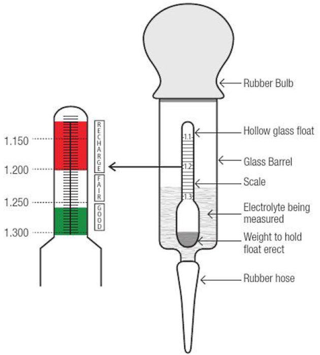
Measuring the Specific Gravity
The specific gravity, also called the relative density, of the electrolyte (the liquid inside the battery) varies proportionally with the amount of charge in the battery.
It is highest when the battery is fully charged and lowest when the battery is fully discharged or flat. It follows that the amount of charge in a battery can be determined by measuring the specific gravity of the electrolyte. A simple, inexpensive device called a hydrometer is used to measure specific gravity.
In general, for a fully charged battery, the specific gravity should measure about 1,250. Half charge will be indicated by a reading of 1,200 and fully discharged by 1,150 All cells in a battery should indicate a similar specific gravity.
A variation of more than about 0,025 will indicate a faulty cell and the battery should be replaced.
Specific gravity readings should not be taken immediately after topping-up a cell as the added water will float towards the top of the cell and give a false reading. Charging for thirty minutes or more after topping-up will mix the electrolyte and allow accurate readings. Top up the battery before charging as the pouring of cold distilled water onto hot acid in the battery will cause splatter. Batteries which have cells where specific gravity readings fail to rise, or respond poorly to adequate charging, should be replaced.
Measuring the On-Load Terminal Voltage
Measurement of the terminal voltage when a battery is supplying current to a load, such as a transmitting radio, will also provide an indication of the amount of charge in a battery. This measurement is known as the on-load terminal voltage.
It will be interesting: Radio Calling Procedures Improving Clarity and Efficiency in Radio Transmissions
For a 12 volt battery, the on-load terminal voltage should not fall below approximately 11,4 volts while transmitting.
If the voltage does fall significantly below this figure, the battery requires charging. If after charging, the on-load terminal voltage still falls significantly below 11,4 volts, it is an indication of a faulty cell and the battery should be replaced. Measurement of the off-load (when the battery is idle) terminal voltage of a battery is a poor indication of its condition.
Loss of Capacity
A battery will suffer a gradual loss of capacity during its life. This is inevitable and the battery should be replaced when the capacity loss becomes significant.
Many lead-acid batteries have a commercial life of only two to three years. However, the useful life of a battery can be considerably shortened by:
- operating a battery in a low state of charge for long periods;
- allowing a battery to stand in a discharged state for long periods;
- leaving a charged battery for long periods without periodic charging; and
- overcharging.
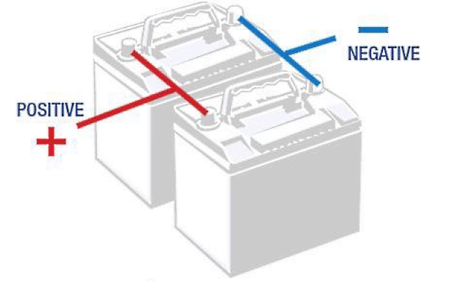
Connection of Batteries During Emergencies
For a vessel with more than a single bank of batteries, it is highly recommended to connect the batteries in parallel during emergency situations. The battery on/off or interchange switch will indicate if this is possible.

- International Maritime Organization. (2017). SOLAS consolidated edition 2017: Consolidated text of the International Convention for the Safety of Life at Sea, 1974, and its Protocol of 1988: articles, annexes and certificates. London: International Maritime Organization.
- International Telecommunication Union. (2020). Radio Regulations. Geneva: International Telecommunication Union.
- International Electrotechnical Commission. (2019). IEC 61162-1:2016 Maritime navigation and radiocommunication equipment and systems – Digital interfaces – Part 1: Single talker and multiple listeners. Geneva: International Electrotechnical Commission.
- International Electrotechnical Commission. (2016). IEC 61162-2:1998 Maritime navigation and radiocommunication equipment and systems – Digital interfaces – Part 2: Single talker and multiple listeners, high-speed transmission. Geneva: International Electrotechnical Commission.
- International Electrotechnical Commission. (2016). IEC 61162-3:2008 Maritime navigation and radiocommunication equipment and systems – Digital interfaces – Part 3: Serial data instrument network. Geneva: International Electrotechnical Commission.
- International Electrotechnical Commission. (2016). IEC 61162-450:2018 Maritime navigation and radiocommunication equipment and systems – Digital interfaces – Part 450: Multiple talkers and multiple listeners – Ethernet interconnection. Geneva: International Electrotechnical Commission.
- International Maritime Organization. (2017). IAMSAR Manual, Volume III: Mobile Facilities. London: International Maritime Organization.
- International Telecommunication Union. (2020). Recommendation ITU-R M.1084-5: Interim solutions for improved efficiency in the use of the band 156-174 MHz by maritime mobile service. Geneva: International Telecommunication Union.
- International Telecommunication Union. (2020). Recommendation ITU-R M.1371-5: Technical characteristics for an automatic identification system using time-division multiple access in the VHF maritime mobile band. Geneva: International Telecommunication Union.
- International Telecommunication Union. (2020). Recommendation ITU-R M.493-15: Digital selective-calling system for use in the maritime mobile service. Geneva: International Telecommunication Union.