This article provides an overview of Inmarsat-A, a satellite communication system that revolutionized maritime communication. We will explore the key components of Inmarsat-A equipment, including both above-deck and below-deck units.
- Communication services – Inmarsat-A
- Inmarsat-A SES equipment
- Above deck equipment
- Below deck equipment
- Antenna direction/tracking
- The Ship’s Plotted Position
- The Ship’s heading (Gyro course)
- Azimuth angle
- Azimuth angle map
- Elevation angle
- Elevation angle map
- Distress Communication
- Distress priority
- How to send a Distress call by telex or telephone
- Urgency and Safety priority
- Making a telephone call
- Sending a telex
- Making a fax or data call
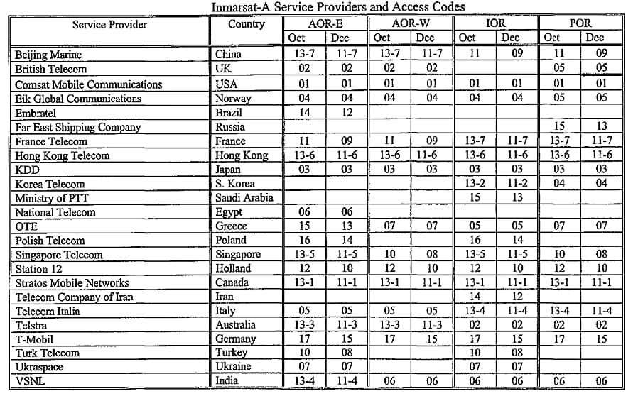
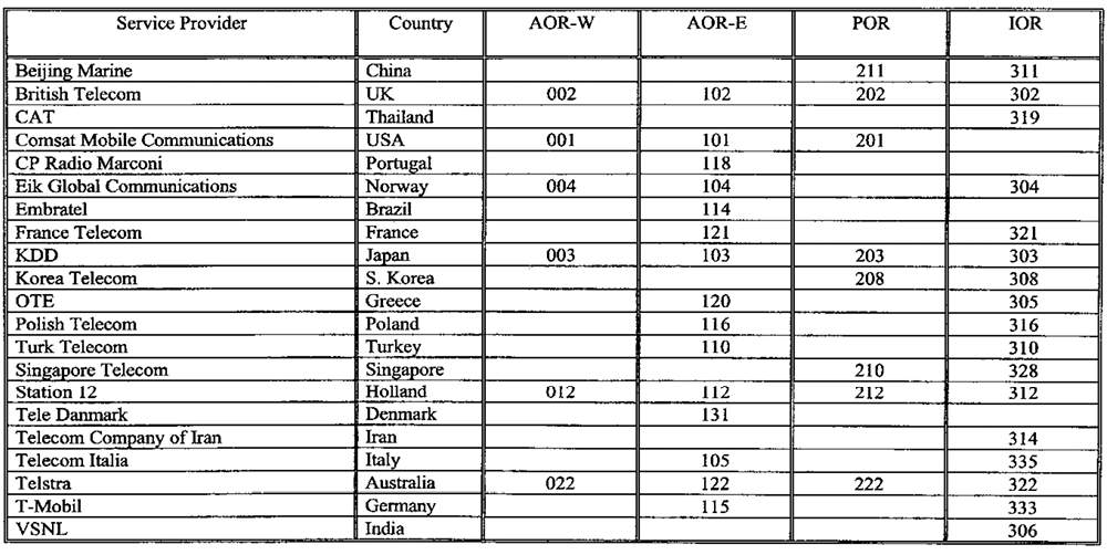
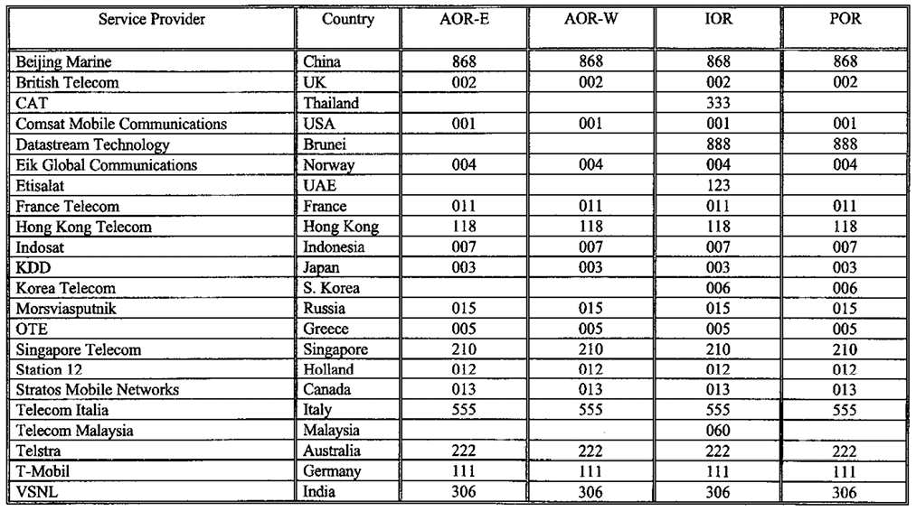
- Inmarsat Service Providers and Access Codes
Furthermore, we will delve into crucial aspects of antenna direction and tracking, including the significance of the ship’s plotted position, heading, azimuth, and elevation angles.
Communication services – Inmarsat-A
The communication services available depend on the type of terminal used. However, the following is a representative selection of services available on Inmarsat-A:
- distress communication;
- automatic dial-up telephone calls;
- automatic dial-up telex calls;
- automatic dial-up facsimile calls.
In addition, there are other services available, such as:
- medium speed data (2,4-9,6 kilobits per second);
- high speed data (56 or 64 kbps);
- slow-scan television;
- voice/data group call;
- international packet switching;
- different services using 2 digit codes, such as: collect calls, credit card calls, time and charge information at the end of communication, technical assistance, maritime assistance, medical assistance, to mention only a few.
You will find details of these function services in the Inmarsat Maritime Communications Handbook.
Inmarsat-A SES equipment
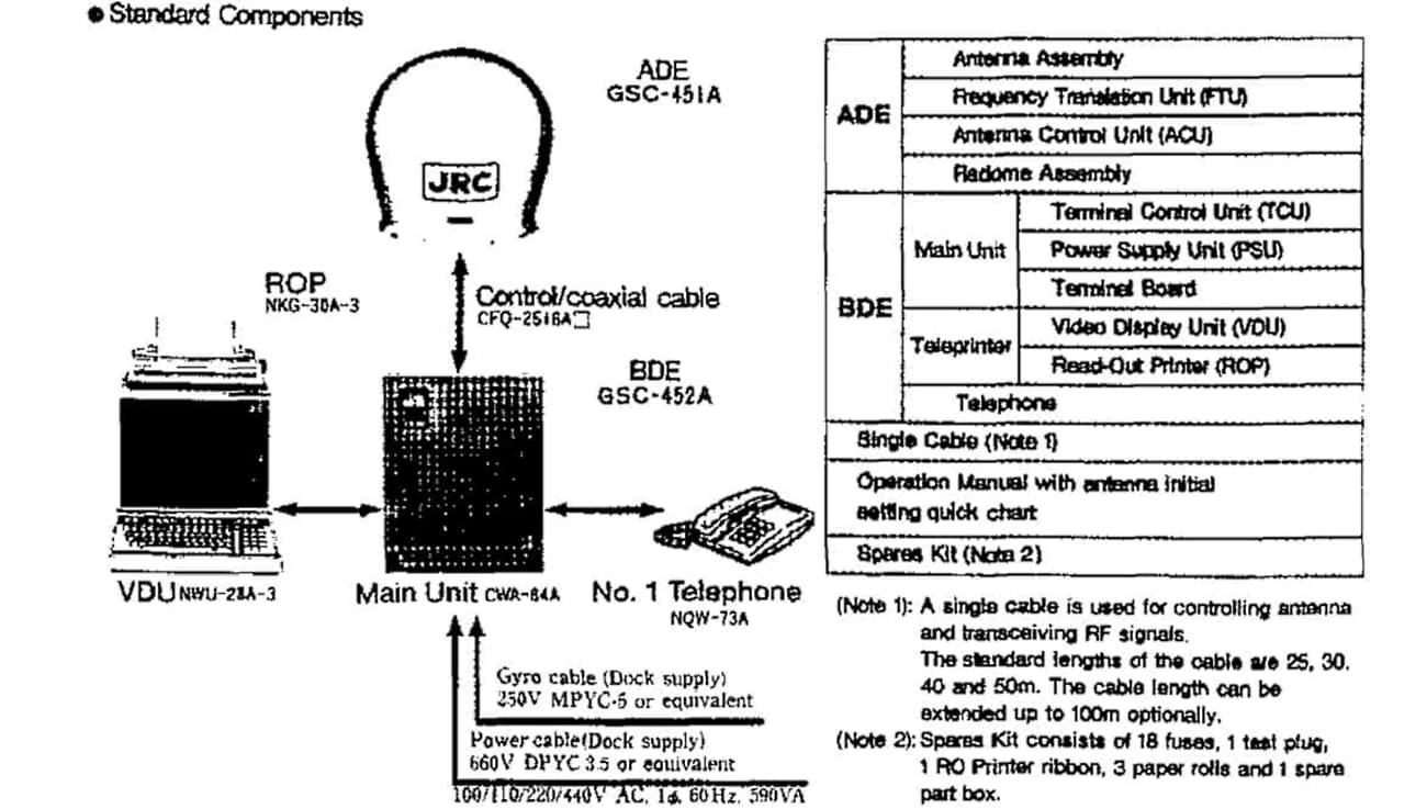
The complete Inmarsat-A station consists of two parts:
- Above deck equipment (ADE).
- Below deck equipment (BDE).
Above deck equipment
Above deck equipment includes a parabolic antenna with a diameter of 0,8 to 1,2 metres.
The large size and weight of the Inmarsat-A antenna has meant that Inmarsat-A SESs have generally been fitted on Fatigue Assessment of Typical Details of Very Large Gas Carriers (LPG)large ships such as oil tankers and trading vessels.
The antenna is mounted on a platform and stabilised so that it remains pointing towards the satellite regardless of the ships’s motion or change of course. It also includes an RF unit (Basic transmitters and receivers in shippingtransmitter and receiver) and a power control unit.
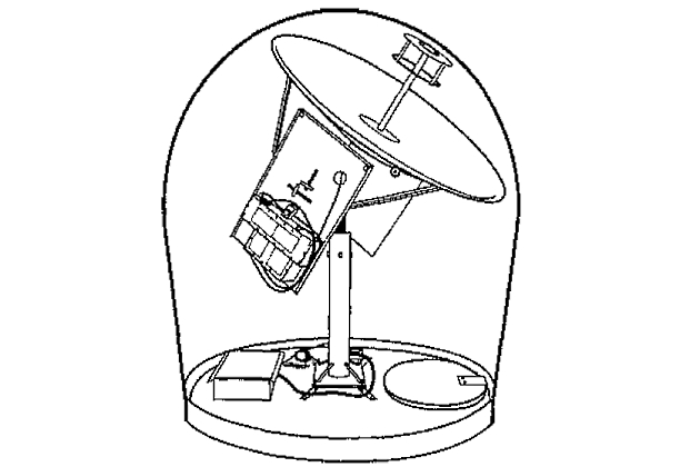
It is highly recommended that one should keep clear o f the SES antenna. When the SES is being used to send or receive a call, the antenna transmits a powerful electro-magnetic field towards the satellite. This field, in the vicinity o f the antenna, could be harmful, and it is therefore important always to keep at a safe distance from the antenna
Stabilised antenna with RF-unit, power supply and control unit. The antenna is protected with an Inmarsat-A gyro radome. Ideally the antenna must have free visibility in all directions over an elevation of 5 degrees. The antenna must therefore be placed as high as possible to avoid blind sectors.
Below deck equipment
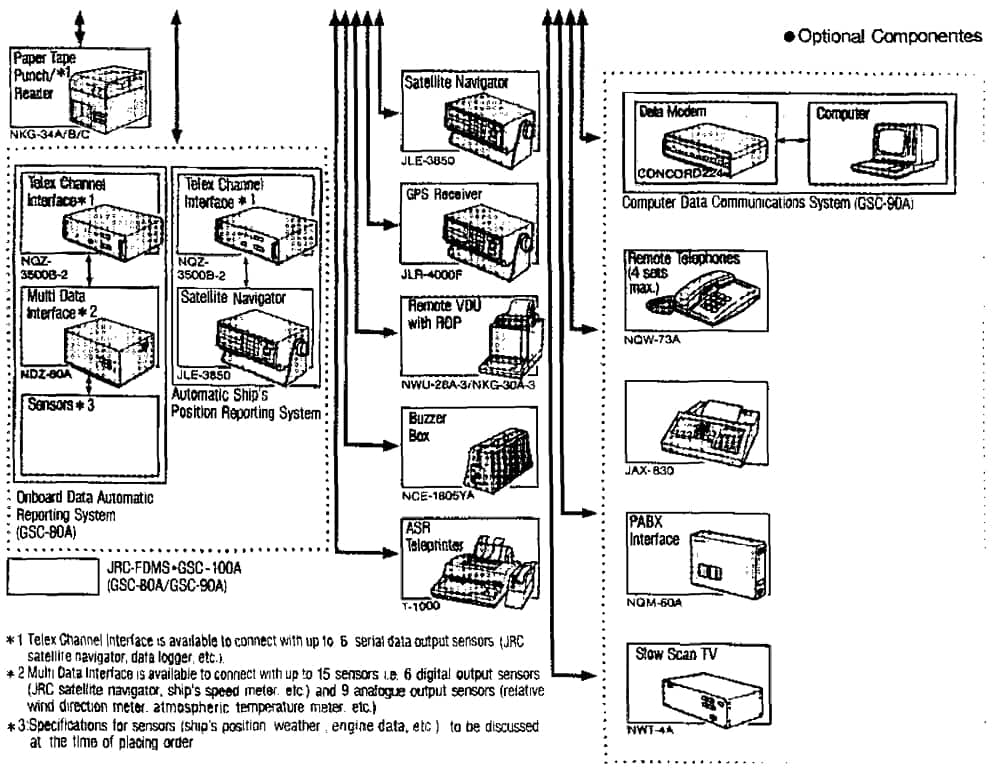
Below deck equipment consists of an antenna control unit, communication electronics for transmission and reception, access control and signalling, and telephone and telex equipment.
Ordinary TELEX (Narrow Band Direct Printing – NBDP) Procedurestelex equipment consists of a CRT screen, a hard copy printer and a keyboard.
By means of this equipment, messages can be edited and transmitted directly to the telex subscriber, or the message can be stored for later transmission.
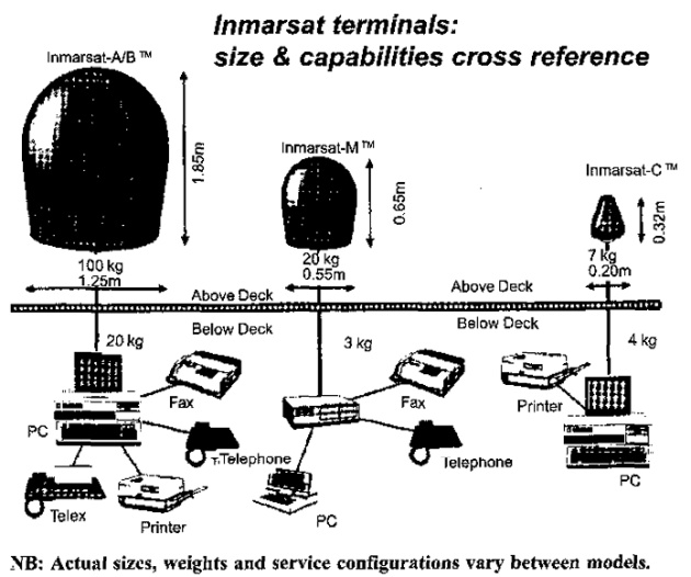
Note that the Inmarsat-A station is continuously updated by the gyro. The antenna will therefore keep contact with the satellites, even if the ship changes its course
Antenna direction/tracking
The antenna is very sensitive, and must be pointed directly towards the satellite in order to obtain maximum reception and transmitting conditions.
During normal operations, the antenna is locked to the satellite automatically (auto tracking).
Read also: Inmarsat: A Guide to Satellite Communication
Today, new terminals are fitted with automatic antenna scanning, allowing the equipment to automatically search for and find the TDM signal from the satellite, thereby eliminating the need for manual input of the azimuth and elevation angles for antenna pointing. Even if the signal is temporarily blocked, (mast, stack, etc.) the system will automatically recover.
When searching manually for the satellite, the following informations is needed:
- The ship‘s plotted position;
- The ship‘s heading (Gyro);
- Azimuth angle for the plotted position;
- Elevation angle for the plotted position.
The following items (“The Ship’s Plotted Position” to “Elevation angle” provide examples of how to direct the antenna.
The Ship’s Plotted Position
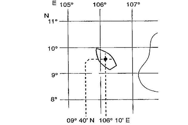
The ships plotted position is needed to decide which satellite can be used.
The Ship’s heading (Gyro course)
The ship‘s heading is necessary for the antennas auto tracking system.

Azimuth angle
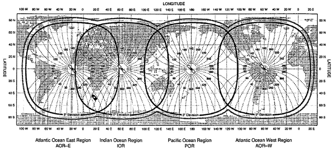
The azimuth angle is the angle between north and the horizontal direction of the satellite, as seen from the ship.

Azimuth angle map
Elevation angle
The elevation angle is the height of the satellite over the horizon, as seen from the ship.
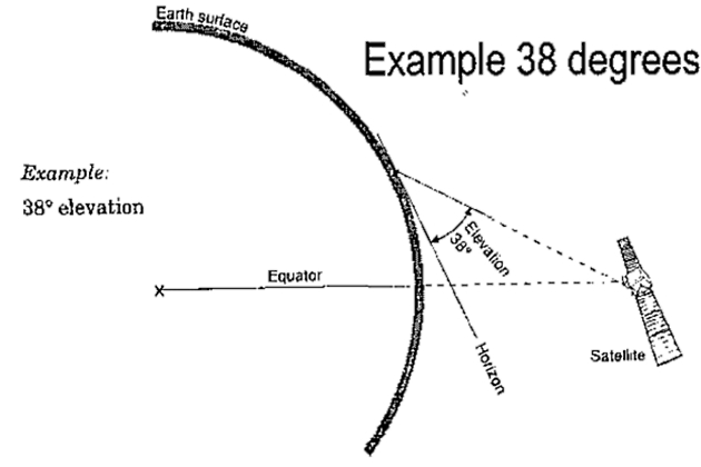
Elevation angle map

Distress Communication
The Distress, Urgency and Safety services are provided to aid the Safety Equipment for Safeguarding Life at Seasafety of life at sea, and should be used in strict accordance with the ITU Radio Regulations. Calls and messages should only be transmitted on the authority of the master or the person responsible for the ship.
Telex mode should be used to avoid any misunderstanding that might arise from misinterpreted voice communications. The English language must be used for all distress communications.
Distress priority
The Inmarsat system, gives Distress Signals And Distress Trafficdistress calls priority 3. This priority should only be used for:
- Making a distress call by telex or telephone (MAYDAY).
- Making a call by telex or telephone when life is in imminent danger.
NOTE! Some CESs will automatically route all calls directly to any associated Rescue Co-ordination Centre (RCC), while with others it is necessary to dial (phone) or type in (telex) the required RCC number.
CESs in the USA will provide operator intercept and assistance for distress message handling if the dialling is incomplete.
Furthermore, the NCS in your Ocean region will intercept the call if you have incorrectly specified a CES (e. g. selected a CES not operating in your Ocean Region) or will direct the call to an associated RCC.
How to send a Distress call by telex or telephone
If the ship is threatened by grave and imminent danger, one can use the SES to send a distress alert.
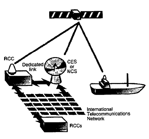
The alert is routed automatically through a CES to a Rescue Coordination Centre.
The procedure for sending a distress alert.
- Select telex or telephone mode of operation.
- Select distress priority.
- Select the required CES.
- Initiate the request in accordance with the equipment manufacturers instructions.
- If no reply within 15 seconds, repeat the distress alert.
- When contact is established, the distress message must be transmitted as follows, in compliance with the ITU Radio regulations:
- The distress signal MAYDAY for telephone/telex.
- The name, call sign or other identification of the Transmission of Urgency and Safety Signals from a Vesselvessel in distress.
- Inmarsat Mobile Number and Ocean region.
- The position in latitude and longitude.
- The nature o f distress.
- Type o f assistance required.
- Any other information which might help the rescue authorities.
Urgency and Safety priority
The priority used for urgency and safety telex/telephone calls is priority 0 (zero). Medical advice, medical assistance and maritime assistance can be obtained from some CESs by using the two-digit codes for these services.
If the CES selected does not support the two-digit code, ask for advice from the CES or select a different CES.
The procedure for sending an urgency or a safety call.
- Select telex or telephone mode of operation.
- Select Routine priority (Priority 0).
- Select the required CES.
- Call the CES. On receipt of the PTS (Proceed to Select) tone, dial in the appropriate two-digit code. On telex, wait for the CES header to be printed on your printer (or VDU), followed by GA+. Then type the two-digit code followed by a + sign.
Medical Advice
When using the two-digit code 32, some CESs will automatically connect the call to a local hospital so that advice may be quickly obtained.
Information required:
- The word MEDICO.
- Name of the ship, call-sign and IMN.
- Position in longitude and latitude.
- The condition of the ill or injured person.
- Any other relevant information.
Medical assistance
When using the two-digit code 38, some of the CESs will connect the calls directly to associated RCC’s so they can be dealt with immediately.
This code should only be used when immediate medical assistance, such as the evacuation of a sick or injured person, is required.
Information required:
- Name of the ship, call-sign and IMN.
- Position in latitude and longitude.
- The condition of the ill or injured person.
- Any other relevant information.
Maritime assistance
When using the two-digit code 39, some CESs will connect the call directly to associated RCC’s. This code should only be used when immediate assistance is required for such things as steering gear failure, man-over-board, oil pollution etc.
This code should also be used when sending a request for towage.
Information required:
- Name of the ship, call-sign and IMN.
- The position in latitude and longitude.
- Particulars of the incidence.
- Any other relevant information.
Making a telephone call
- Select the CES Access Code for the CES through which you want to communicate.
- Initiate a telephone request in accordance with the manufacturers instructions.
- On receipt of the PTS (Proceed to select) tone, type in the following digits using the telephone keypad:
- 00 – is the two-digit code for automatic call request.
- # – is the key for ending the calling sequence.
Sending a telex
- Select the CES Access Code for the CES through which you want to communicate.
- Initiate a telex request in accordance with the manufacturers instructions. Within 12 seconds your SES should have received a Telex channel assignment, and completed the “handshake” with the CES.
- When the CES header is printed on your printer (or VDU), followed by GA+ type in the following digits using the telex key board:
- 00 – is the two-digit code for making an automatic call.
- + – is the key to end the calling sequence.
Making a fax or data call
- Select the CES Access Code.
- Initiate a telephone request for an uncompanded channel in accordance with the manufacturers instructions.
- On receipt of the PTS tone, type in the following digits on your fax machine:
Data or fax (group 3 fax machine) should preferably be installed on the Second IMN of the SES, with the SES in auto-answer mode.
Furthermore, it is recommended that the SESs, when engaged in sending facsimile or data traffic, specify an uncompanded channel in their request burst.
It will be interesting: The Global Maritime Distress and Safety System – Principles & Practice
Shore-originated calls can be set up using uncompanded channels. This is accomplished by placing the digits 81 after the ocean region code and before the ship‘s IMN when calling the ship.
Inmarsat Service Providers and Access Codes
