The SART is a radar transponder designed for search and rescue operations, helping to localize life rafts and lifeboats after damage at sea or shipwreck. It is designed to be put on stand-by on the removal of a switch block, and to automatically respond only when interrogated from a 9 GHz radar (x-band radar or 3 cm radar).
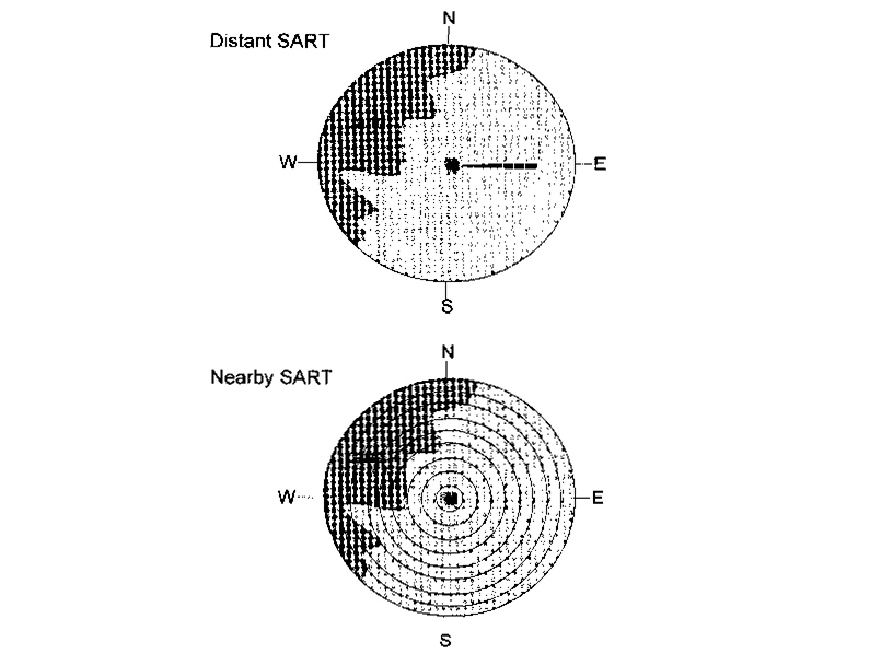
When activated by a radar, the SART transmits 12 swept frequency signals, which are displayed as a line of 12 blips on the radar screen. The blip line extends over 8 nautical miles outward from SART position, clearly identifying the survival craft.
Range performance
A SART mounted 1 meter above sea level will operate correctly when interrogated by The Structure, Functions and Details of Professional Marine Radio Communicationnavigational radars with an antenna height of 15 meters, at a distance of at least 5 nautical miles. When interrogated by airborne radars with peak power of at least 10 Kw and an altitude of 3 000 feet, the distance is increased to 30 nautical miles.
On board the survival craft, the survivors will receive an audible and visual signal from the SART, indicating that their SART signals have been received by an approaching vessel.
| Detection range of SART | |
|---|---|
| SART lying flat on the floor | Range 1,8 nautical miles |
| SART standing upright on the floor | Range 2,5 nautical miles |
| Sart floating in the water | Range 2,0 nautical miles |
Categories of SART
Radar transponders are grouped into three categories:
A. SART for fixed installation in lifeboat, raft or own vessel.
B. Portable SART
C. SART mounted in release mechanism and/or combined with float-free EPIRB.
Test procedure
- Set radar range to approx. 10 nautical miles.
- Observe the radar screen.
- Activate the radar transponder by switching to “TEST” position.
- Check the radar display to ensure that 12 or 24 rings are observed.
The transponder responds with a continual tone and the LED indicator shines continuously.
Specifications
The SART must be designed to conform to all applicable regulations and standards including IMO performance standards, Regulations and Traffic ProceduresRadio Regulations, CCIR Recommendations and IEC standards.
| Frequency range: | 9 200 – 9 500 MHz. |
| Battery capacity: | 96 hours in stand-by, and 8 hours in transpond mode. |
| Polarization: | Horizontal. |
| Response signal: | 12 sweeps. |
| Output power (EIRP): | Not less than 400 mW. |
Labels and marking
The SART must be permanently marked with make, type and serial number.

The markings must also include operation instructions, battery expiry date and vessel identification.

Source: Depositphotos
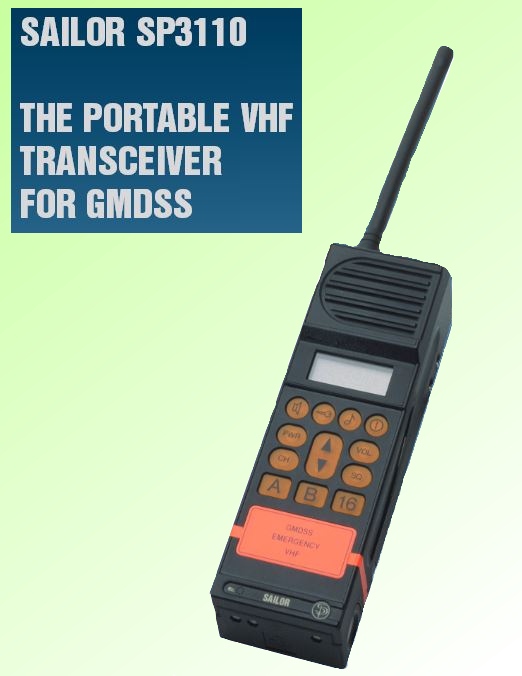
Portable VHF Transceivers
Portable VHF transceivers are designed to take care of “on-scene” (short range) communication needs after a shipwreck. GMDSS approved transceivers must comply with IMO Resolution A.605 (15), “Performance Standards for Survival Craft Two-way VHF radiotelephone apparatus, with regard to functional requirements and watertightness.”
Requirements:
- Ships between 300 and 500 gross tons: 2 pieces.
- Ships of 500 gross tons and upwards: 3 pieces.
The obligatory portable VHF’s shall, when not in use for on-board communication, be kept in charging brackets on the navigating bridge, and be kept fully charged at all times.
Read also: Maritime Safety Information Under the GMDSS (The Global Maritime Distress and Safety System)
If the equipment is used for GMDSS Distress and Safety Communicationson-board communication, an additional set of emergency batteries (i. e. Lithium batteries) must be kept fully charged on the bridge.
The ship’s call sign must be water resistantly marked on the transceiver. Also all channel numbers must be indicated on the equipment.
Technical specifications:
- Power output: 0,25 – 1,0 watt.
- Channels: channel 16 and international simplex channels.
- Battery capacity: Approximately 8 hours.
VHF Emergency Communication Set
The VHF The Essential Guide to Emergency Radio Beaconsemergency communication set is a battery operated transceiver that works on the 121,5 MHz and 123,1 MHz frequencies. The purpose of this transceiver is to maintain communication with aircraft and vessel in distress/rescue vessel. 121,5 MHz is the civil aviation emergency frequency, whereas 123,1 MHz is a priority frequency used by the rescue services and participating units in a rescue operation. The transceiver is mandatory on board passenger ships sailing in international waters in accordance with specific regulations. The equipment must be waterproof, easy to operate when wearing a survival suit (gloves) and fulfil certain other requirements, e. g. with a view to battery capacity and colour.
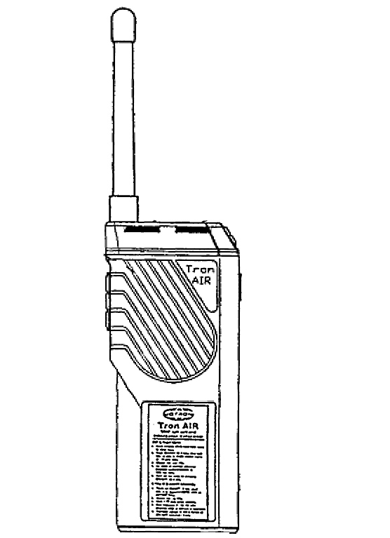
Technical specifications of a TRONAir:
- Output: 50 – 200 mW.
- Frequencies: 121,5 – 123,1 MHz.
- Battery capacity: Approx. 8 hours with the following ratio 1:1:8, i. e. 1 part transmitting, 1 part receiving and 8 parts on standby.

- Global Maritime Distress and Safety System: IMO 1987.
- Manual for use by The Maritime Mobile and Maritime Mobile- Satellite Services: ITU 1992.
- Radio Regulations 1-2-3: ITU 1990.
- Manual for Norwegian Mobile Radiotelephone Stations: The Norwegian Telecom 1992.
- Modem Electronic Communication: Gary M. Miller 1978.
- Brochures and data sheets from manufacturers of GMDSS Equipment.
- Inmarsat: Inmarsat-A User’s Manual, Inmarsat-C User’s Manual.
- Nodposisjonering: Bjomar Augdal, 1992.
- Skipsantenner: Bjomar Augdal 1991.
- COSPAS-SARSAT Secretariat: COSPAS-SARSAT System Data Documents.
- Admiralty List of Radio Signals.