Manoeuvring and ship handling has always been a challenge for ship designers and naval architects. To have an adequate understanding and an anticipated knowledge about the vessel’s manoeuvring characteristics and behaviour in confined waters, is an important aspect of the marine safety and protection of the marine environment. In addition, the safety of the crew and staff operating the vessel needs to be maintained.
- Manoeuvring characteristics
- IMO Standard manoeuvring tests and criteria
- Turning circle manoeuvre
- Zig-zag manoeuvre
- Stopping test
- Test conditions
- Test criteria
- Comments to the IMO Standards
- Additional manoeuvres
- Low speed manoeuvres
- Manoeuvring prediction methods
- Database method
- Model tests
- Mathematical and empirical methods
As long as travelling at sea has been possible and trading across continents have been a sustainable development of countries, there have always been a need for a standardization of ship design and operational safety aspects. Developing international regulations for improving safety at sea that is followed by all shipping nations have been adapted several times from the mid-19th century. After the accident of the Titanic in 1912, the first convention addressing the safety of life at sea (SOLAS) was held. Which is the most important treaty addressing marine safety.
It was first in the year 1948 that such a convention was adopted. In Geneva, the formal establishment of the International Maritime Organization (IMO) was conducted. Ten years later, in 1958 the convention entered into force. The IMO is a United Nations agency regulating manoeuvring performances of ships to ensure safety, which is the key driving force of the organization. Its main purpose is related to security and safety of shipping and the prevention of marine pollution.
IMO’s mission statement:
“The mission of the International Maritime Organization (IMO) as a United Nations specialized agency is to promote safe, secure, environmentally sound, efficient and sustainable shipping through cooperation. This will be accomplished by adopting the highest practicable standards of maritime safety and security, Conversion of the Vessel in LPG Carrier to River-Sea Navigation on Danube Riverefficiency of navigation and prevention and control of pollution from ships, as well as through consideration of the related legal matters and effective implementation of IMO’s instruments with a view to their universal and uniform application.”
To confirm the vessel’s compliance with the Standards, full-scale trials must be conducted. The full-scale trials must also be performed according to the Standards. The Standards refers to IMO’s three required manoeuvring tests, presented below in IMO Standard manoeuvring tests and criteria. Some of the parameters influencing the manoeuvrability are the main dimensions of the vessel, its hull shape, speed and propulsion system. These are all decided and calculated in the design stage.
Manoeuvring characteristics
IMO addresses the Standard manoeuvrability characteristics for a ship by typical measurements of the vessel’s performance quality and handling ability.
Inherent dynamic stability/straight line stability
If a vessel on a straight course is exposed to a small disturbance, which sets it off course, and soon after settles a new straight course, without needing to correct with a rudder, the vessel is said to be dynamically stable. The degree of inherent stability and the magnitude and duration of the disturbance will affect the resulting deviation.
Course-keeping ability
The course-keeping ability is a measure of the steered vessel’s ability to maintain a straight predetermined path direction without having to use corrective rudder. If the vessel suffers from small inherent dynamic stability, reasonable course control is allowed.
Initial turning/course-changing ability
The change-of-heading response to a moderate helm is defined as the the vessel’s initial turning ability. This can be measured in terms of either heading deviation per unit distance sailed, or in terms of the distance sailed before a certain heading deviation (e. g. time to second execute in a zig-zag manoeuvre) is reached.
Yaw checking ability
The measure of the counter-rudder applied in a certain state of turning is called the yaw checking ability of the vessel. E. g. for a zig-zag manoeuvre, this can be the heading overshoot reached before the yawing tendency has been cancelled by the counter-rudder.
Turning ability
The measure of the vessel’s ability to turn using the hard-over rudder is called the turning ability. The results may be given by either minimum advance or tactical diameter, where both can be determined by a turning circle manoeuvre.
Stopping ability
The measured “track reach” and “time to dead in water” is the vessel’s stopping ability. This can be measured in a stop engine-full astern manoeuvre, executed in the end of a steady approach at full test speed.
IMO Standard manoeuvring tests and criteria
Three required manoeuvring tests has been defined by IMO to help assist in design, construction and operation of ships. These tests are used in evaluating the ship’s manoeuvring performance according to the Standard. The tests are hence referred to as the Standard manoeuvring tests. These tests will measure the manoeuvrability of the vessel and evaluate its characteristics based on the conventional trial manoeuvres.
The three manoeuvring tests are the turning circle manoeuvre, the zig-zag manoeuvre and the stopping test manoeuvre. By executing a turning circle, the turning ability of the vessel can be determined. The course-keeping and initial turning/course-changing ability can be determined by a zig-zag manoeuvre. Finally, the vessel’s stopping ability can be found from the stopping test manoeuvre. The following sections describe the three manoeuvres in more detail.
Turning circle manoeuvre
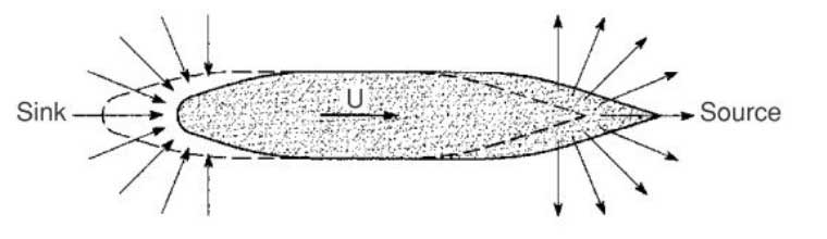
The turning circle manoeuvre is performed to both starboard and port. The vessel is set to a fixed heading with no measured yaw rate. When heading and test speed is achieved, the rudder is set to a 35° angle or maximum design rudder angle permissible at the test speed. When the vessel has preformed a 360° change of heading, the test is complete. The essential information extracted from this manoeuvre are tactical diameter, advance and transfer, see Picture 1.
Transfer is the transfer (deviation perpendicular to the original heading) at a 90° change of heading. Tactical diameter is the transfer at a 180° change of heading. Advance is the distance travelled by the vessel along the original course until a 90° change of heading is achieved. The distance is measured from the point where the rudder is put over.
Zig-zag manoeuvre
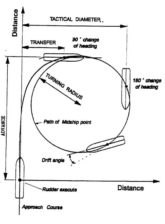
The zig-zag manoeuvre is also executed to both starboard and port. When the vessel is on a straight course, a specific amount of rudder angle is applied (“first execute”). When the specific course alteration from the original heading is achieved, the rudder is alternately shifted to either side (“second execute” and so on). There are two types of zig-zag manoeuvres described in the Standards. The 10°/10° and the 20°/20° zig-zag test. The 10°/10° zig-zag test uses a 10° rudder angle until a course change of 10° from the original heading is achieved. The 20°/20° zig-zag test is executed correspondingly with 20°.
Read also: Regulations and Rules for Vessels to Carry Liquefied Gas
The desired information to extract from this test are the overshoot angles, initial turning time to second execute and the time to check yaw (the time between the rudder execute and the time of the maximum heading change in the original direction). The overshoot angle is the difference in angle between the rudder execute and the continuous turning of the vessel until it changes its direction (corresponding to the yaw checking ability). The first and second overshoot angle corresponds to the second and third rudder execute, respectively. See Picture 2.
Stopping test
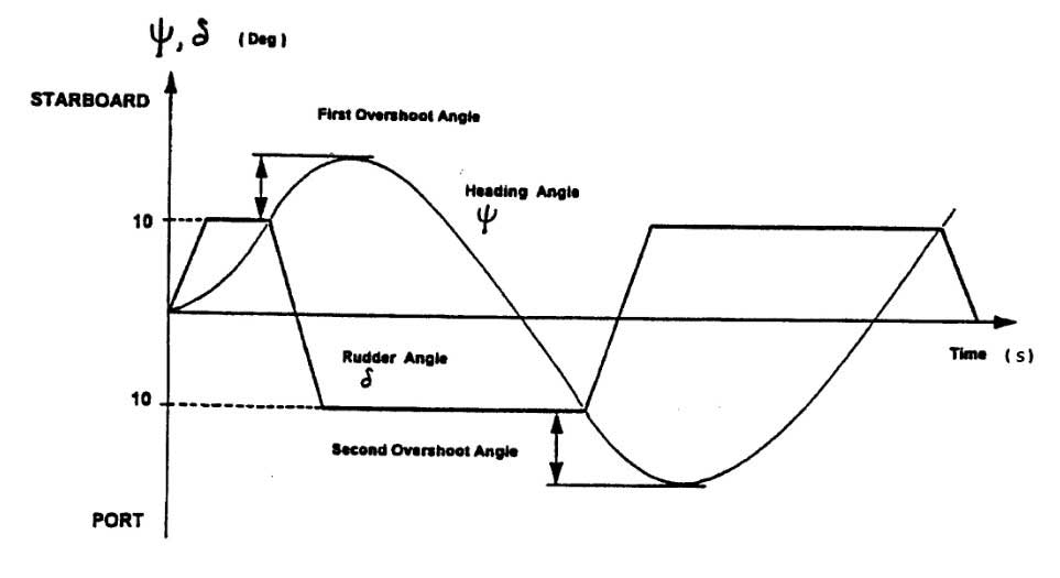
The stopping test is performed when the vessel is at full ahead speed. At this moment, the full astern power command is given and the ship’s speed reduces until a zero value of the speed is achieved. During the trial, the rudder should be placed in midship position. The parameters of interest are the head reach, track reach and the lateral deviation. The head reach is the distance travelled along the ship’s original course from the astern order command is given, until the ship is “dead in water”. The track reach is the total distance sailed in the ship’s path. Lateral deviation is the distance to either starboard or port, perpendicular to the ship’s initial course. See Picture 3.
Test conditions
In order to evaluate the manoeuvring tests and characteristics properly, the manoeuvring tests should be conducted to both starboard and port under the following conditions:
- Deep, unrestricted water: more than 4 times the draught;
- Calm environment;
- Full load, even keel condition;
- Steady approach at the test speed, and;
- The test speed is at least 90 % of the ship’s speed, corresponding to 85 % of the maximum engine output.
Test criteria
The test criteria defined by the IMO are explained as follows:
* Turning ability
- Tactical diameter should not exceed 5 ship lengths in the turning circle manoeuvre.
* Initial turning ability
- With the application of a 10° rudder angle to port/starboard, the ship should not travel more than 2,5 ship lengths by the time the heading has changed by 10◦ from the original heading.
* Yaw checking abilities and Course keeping ability
- the value of the first overshoot angle in the 10°/10° zig-zag test should not exceed:
- 10°, if L/V is less than 10 seconds (L = ship length, V = test speed);
- 20°, if L/V is 30 seconds or more;
- degrees, if L/V is 10 seconds or more but less than 30 seconds.
- The value of the second overshoot angle in the 10°/10° zig-zag test should not exceed the above criterion values for the first overshoot by more than 15°.
- The value of the first overshoot angle in the 20° 20° zig-zag test should not exceed 25°.
Nomenclature for all the formulas you can see here: Nomenclature and Greek Symbols
* Stopping ability
- The track reach in the full astern stopping test should not exceed 15 ship lengths.
Comments to the IMO Standards
Since the IMO resolution A751(18) was accepted in 1993, compliance of these standards have been the foundation in design of ships. The standards are focused on conventional vessels such as displacement ships, like bulk carriers and tankers, propelled by standard propulsion (propellers and rudders). Sailing in restricted waters and impact of environment (i. e. wind, waves and other vessels) are not a part of the standards, with an exception of current in the turning circle manoeuvre. As a consequence of this, ships are constructed to “only” fulfil the design criteria given by the IMO resolution A751(18). Some vessels should, in addition to the IMO requirements, fulfil specific “mission-related” requirements. Which could be specific low speed manoeuvres for determining the manoeuvring abilities in quay areas.
Such performance qualities would not be needed for other vessels such as bulk carriers and tankers, as they are guided by tugs near port. In the wide se- lection of different ship designs and special purpose vessels available to this date, the IMO requirements relate to only a small portion of what is considered as safe manoeuvring. The standards should be viewed as a minimum requirement to fulfil and several more tests, especially mission-related tests, should be conducted and reviewed before letting a vessel sail.
Additional manoeuvres
In addition to the mandatory manoeuvring tests listed in IMO’s standards there are several other tests recommended by various organizations. These tests are however not examined in this thesis and will not be explained in detail. For further information about the different tests, it is referred to the ITTC – Recommended Procedures.
An overview of some different manoeuvring tests is listed below:
- Modified zig-zag manoeuvre test;
- Zig-zag manoeuvre at low speed test;
- Direct spiral test;
- Reverse spiral test;
- Pull-out test;
- Stopping inertia test;
- Parallel course manoeuvre test;
- Thruster turning test;
- Accelerating turn test.
Low speed manoeuvres
The thruster turning test and the accelerating turn test are considered low speed manoeuvres. As MF Landegode needs to perform turning manoeuvres in the quay area, these tests have been conducted during sea trials and will be explained in the following.
Thruster turning manoeuvre
The thruster turning test is not specified in the “IMO MSC Circ. 1053” and is not viewed as a standard manoeuvring test. The manoeuvre is explained in the “International Standard ISO 13643-2 Ships and marine technology – Manoeuvring of ships”.
The vessel is turned by means of its thrusters to starboard by 60° from its initial heading (into the wind). The time measured at heading changes of 15°, 30° and 60° are to be obtained. When a heading change of 60° is reached, the thrusters are reversed and the overshoot angle and time are recorded. The test is then performed to port. The test should be performed with all possible combinations of bow and stern thrusters. The results of the thruster turning test at zero speed can be presented as shown in Picture 4.
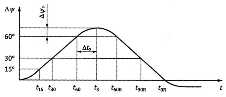
The data to be obtained from the thruster turning test are:
- Time to turn 15° – t15;
- Time to turn 30° – t30;
- Time to turn 60° – t60;
- Time to return turn 60° – t60R;
- Time to return turn 30° – t30R;
- Time to return turn 0° – t0R;
- Overshoot time – Δts;
- Overshoot angle – Ψs;
- Threshold speed – VL.
Accelerating turn test
The accelerating turn test is, as the thruster turning test, not described by the “IMO MSC Circ. 1053” standards. A description of the manoeuvre can be found in the “International Standard ISO 13643-2”, with guidelines of what to obtain from the measured data.
The manoeuvre starts with zero speed and the main propulsion unit set at half MCR. At the same time, the rudder is applied hard over, or the desired degree of interest, in the specific direction as quickly as possible. The settings are kept in these conditions until the vessel achieves a steady turn and the manoeuvre is complete, i. e. the vessel has performed a turn of at least 180°. Picture 5 depicts the trajectory of the manoeuvre and the data to be obtained.

The key 1 denotes the point, where the manoeuvre commences and 2 denotes the trajectory.
The data to be obtained from the accelerating turn test are:
- Advance – x090;
- Maximum advance – xMAX;
- Maximum opposite transfer – y0OPP;
- Transfer – y090;
- Tactical diameter – y0180;
- Maximum transfer – y0MAX;
- Time to turn 90° – t90;
- Time to turn 180° – t180;
- Speed at 90° of heading – V90;
- Speed at 180° of heading – V180.
Manoeuvring prediction methods
To be able to predict a vessel’s manoeuvring behaviour at the design stage is very useful in means of detecting errors and characteristics that need alteration or modification. It is then easy to do changes on the model to get the preferred results. The predictions must be made on the basis of the vessel’s main dimensions, line drawings and other relevant information available at the design stage. There are a variety of manoeuvring predictions available, varying in accuracy and cost.
There are mainly three basic methods:
- Database method;
- Model test, and;
- Mathematical and empirical methods.
Database method
The database method uses predictions and experience from existing data. When using the database method, the existing ships must preferably have similar manoeuvring characteristics as that which are intended for the new ship. The manoeuvring performance of the new ship is then predicted without having to do simulations or model tests. The predictions are based on the vessel’s main dimensions, line drawings and relevant information available at design stage. Typical ranges for the main parameters of the ships are set so that there is a form of similarity requirement between the investigated ship and the ships in the database. Typical parameters and ranges can be viewed below.
Model tests
Predictions made on the basis of model tests are considered to be the most reliable method. However, the lack of full-scale trials and manoeuvring standards has made this prediction method less accurate than other model test areas. All though, more and more full-scale trials are being conducted, and manoeuvring standards for the vessels have been introduced. This will result in a need of more accurate validation of model tests. There are mainly two model test methods used in manoeuvring prediction. The free-running model test, which duplicates the full-scale manoeuvring tests and provide a direct result to the manoeuvring characteristics. The other, a captive model test that measures the forces which are needed to excite the model in a specific manner. The manoeuvring coefficients are provided and used for the prediction of the response.
1 Free-running model
The same model that is used for resistance and self-propulsion tests can be used when doing a free-running model test. This will reduce the cost, since a separate model for manoeuvring tests won’t be needed. The large model is also beneficial regarding scale effects. The free-running test can be conducted in a towing tank, if the tank is wide enough to perform a 10°/10° zig-zag manoeuvre. Large ocean basins are also well suited for free-running tests. Manoeuvring tests with a free-running model will always suffer from scale effects.
The most common free-running model tests are turning circle, zig-zag manoeuvre and spiral test. The results can be directly compared with the Standards for manoeuvrability. Deriving the manoeuvring coefficients from free-running model tests has recently become more frequent. The coefficients are used in mathematical models predicting the manoeuvring characteristics. Oblique towing and propulsion tests have been combined with parameter identification to provide the coefficients.
2 Captive model
Captive model tests are preformed using oblique towing, rotating-arm facilities and Planar Motion Mechanism (PMM) systems.
PMM systems are the most commonly used methods for captive model tests. By combining static or oscillatory modes of drift and yaw, the PMM system can simulate any kind of motion. Captive model tests will also suffer from scale effects. The intention of the motion simulation is to retrieve information on specific parts of the larger complete manoeuvres. The forces measured on the model are used to derive its Introduction to the Standard Simulation Tests and Requirements for Naval Hydrodynamicshydrodynamic coefficients.
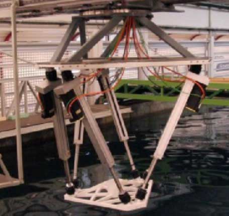
The hydrodynamic coefficients are then used in mathematical models to predict the manoeuvring characteristics. The PMM system is mainly used in long and narrow towing tanks. The PMM tests conducted at MARINTEK are executed using a multi-purpose carriage with a 6 DOF hexapod motion platform in the towing tank. With a maximum carriage speed of 5 m/s, the hexapod is free to move in all DOF.
The rotating-arm facility is in principal a basin with an arm in the centre. The model is mounted on the arm, which rotates in circles while varying the diameter for each test. The coefficients related to turning and the combination of turning and drift, are determined as the hydrodynamic coefficients. The results are, as in the PMM test, used in a mathematical model predicting the manoeuvring characteristics.
Mathematical and empirical methods
The dynamics of a manoeuvring ship can be described by numerical simulations. A set of equations are used in prediction at the design stage. This can be helpful in order to obtain a quick prediction of the manoeuvring characteristics at an early stage of design. The hydrodynamic forces used in the equations are found by empirical methods or theoretical methods. Empirical methods are low cost methods that provide quick results.
The empirical methods have a restriction regarding the similarity needed between the vessels that they are based upon.
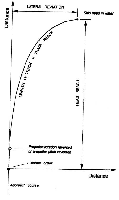
Often used theoretical methods are slender body theory and viscous flow methods using computational fluid dynamics (CFD). The CFD methods are mainly used with Reynolds averaged Navier Stokes (RANS) calculations. The limitations of using CFD-methods are high computational time and large computer resources, like supercomputers, to achieve better results and calculate larger operations. Sink/source models can be used to represent the flow caused by a ship as a source (sink) distribution along the ship’s hull. Velocity vectors are generated and the forces acting from the ship can be calculated. MARINTEK uses such models in their calculation programs VeRes and WAMIT. The sink/source principle is depicted in Picture 7.