Welcome to the forefront of LNG tank level gauging technology. In this article, we delve into the intricacies of various gauge systems designed to optimize efficiency and safety in LNG storage. From traditional float-type gauges to cutting-edge radar systems, explore the evolution of level monitoring and high-level protection devices, revolutionizing the management of LNG reserves.
Reference: SIGTTO “LNG Shipping Suggested Competency Standards”, Sections:
1 Have an awareness of the purpose and operating principles:
- level gauging system;
- high-high level protection devices.
2 Know and understand their principles, operating requirements, likely problems and maintenance procedures:
- float type;
- capacitance type;
- radar type;
- sighting board type.
Level gauging system
All level gauging equipment, used for measuring the liquid levels in cargo tanks during load and discharge, must be designed and developed specifically for the cryogenic low temperatures on LNG carriers. There are several different types of system.
The radar type system has become the most common in use. The values are continually updated and relayed to the operator in the CCR.
The level gauge type is float that employs a tensator spring as a counter balancing mechanism to maintain a constant tape tension at the float. This ensures that the float remains at the same level of immersion, regardless of the amount and weight of the tape paid out.
The accuracy of a Volume measurement methods of LNG transferredgauging system depends on the tank construction and the operating conditions, but tests show that the gauge accuracy should remain within 1 cm.
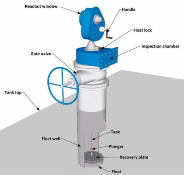
Float type gauge
Perforated invar tape transmits float movement to a sprocket wheel, which in turn drives a counter mechanism that provides local mechanical readout. This is visible through a window in the counter housing.
Level gauge assembly
The level gauge is comprised of the gauge head and the float assembly. The float is clamped to:
- an accurately perforated tape manufactured from invar;
- a viscous damper to control the rate of descent of the float to the cargo level;
- a crank for raising the float to the storage position;
- a mechanical read out that is observed through the counter window.
A float lock-up arrangement provides isolation of the level gauge from the tank when in the stored position. It also provides a gauge datum reference and a means of locking the float in the storage position.
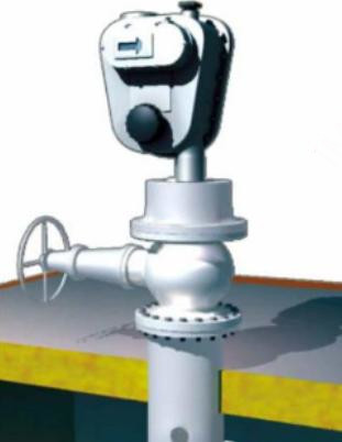
Operating a “Whessoe” level gauge
To obtain the liquid level, the float is released from its stowage position using the release lever located at the base of the gauge head. In the event of a viscous damper failure the float should be lowered to the liquid surface by hand.
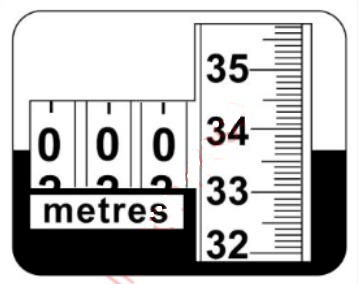
The tank sounding may then be taken, by observation of the local mechanical read-outs, to provide level indication.
The Whessoe gauges should be checked against the custody transfer system (CTMS) during each loading. Cargo tanks must be fitted with a primary and secondary level gauging system. Until recently the back-up system was a mechanical one, such as Whessoe. However, on recent builds both the primary and secondary gauging systems are radar based.
Returning the Gauge to the Stored Position
- turn the crank handle in the “wind up” position;
- raise the float steadily, at a rate of 1,5 m/sec, in an anti-clockwise direction. This is indicated by the arrow on the main cover inspection plate;
- watch the read out counter, which will indicate when the float nears the top. At approximately 2 m from the top, slow down the rate to allow the float to pass through the isolating valve;
- when resistance is felt by the float touching the cushion spring, continue cranking until the plunger is seated, which seals the gauge from the tank, and the automatic float lock-up and datum plunger spring fully inward, which secures the float;
- check that the counter reads exactly the same before and after use.
Move the crank handle to its “storage” position (inboard).
The crank handle is designed to drive in one direction only and is spring loaded by a cam arrangement so that it is not in motion during normal gauging.
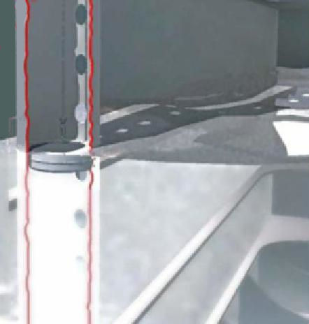
Innage measurement
Zeroing of the gauge counter must be carried out when the float is resting on the anchor bar.
In the image shown, if the tank datum is the bottom of the tank, the level gauge counter must be set to the value of the distance from the bottom of the tank to the flotation line on the float (based on the float immersion from the specific gravity/immersion table).
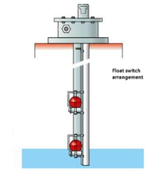
High-high level protection devices
In addition to the cargo level gauging system, there are at least two independent devices fitted on the tank domes that provide alarms when the cargo level reaches a certain value.
There are 3 levels of alarm. The CTMS alarm settings will be as approved by the flag State/Classification Society. In this example, the settings are based on a filling level of 98 %:
- A high level alarm at 95 % of the tank volume (audio-visual warning). This early warning alarm can be activated by the tank level measuring system or by an independent sensor;
The percentage level settings for the high, high-high and extremely high level alarms can only be adjusted if overseen by Class.
- a high-high level alarm at 98,5 % of the tank volume (an audio-visual warning that differs in sight but not in sound from the 95 % alarm). The isolation of the overfilled tank will automatically take place when the tank loading valve is shut. If the high level warning alarm is activated by the tank level measuring system, the high-high level alarm must be activated by an independent sensor;
- an extremely high level alarm at 99 % of the tank volume (audio-visual warning that differs in sight from the 95 % and 98,5 % alarms). The ESDS will be automatically activated. If the high level alarm is activated by the tank level measuring system, then the extremely high level alarm must be activated by an independent sensor.
During Preparation of loading and unloading operations for LNG/LPG carrierscargo loading there is a danger of generating a significant surge pressure if the valves close against the shore pumping system. For this reason the closing times of the valves, together with the valve characteristics, must be available to the terminal so that loading rates can be adjusted.
The float gauge is a “closed” gauging device, which means that no cargo vapour is released to the atmosphere during gauging. Float gauges are used on many LNG carriers but, generally, fulfil the role of back up gauging devices to the CTMS.
Level gauges, such as “Whessoe” gauges, are fitted with transmitters for remote monitoring.
Float type gauge
A float level gauge is generally inaccurate when recording the bottom 10-15 cm of liquid in a tank.
When not in use, float gauges should be housed or the sloshing effect of the cargo will damage the tape-tensioning device and the float may be parted from the tape.
It is important, when using the float gauge, that it should be lowered into the tank for a minimum of 15 minutes before measurement to allow the tape to cool to the temperature in the tank.
The “average level” reading is the mean of five readings from the float gauge at 30 second intervals, with each reading being to the nearest 1 mm.
Twelve inch float well
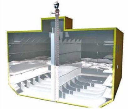
The float gauge is sheathed in a tubular 12′ (305 mm) well tube installed vertically within the cargo pump tower. The upper end of the float well penetrates the top of the tank dome, where it terminates in a flange.
The lower end extends to within 75 mm of the bottom of the tank, where it is closed by a perforated plate. The lower end of the float well is provided with a bolted inspection cover. Expansion is allowed for by a sliding connection that is just below the dome penetration.
To avoid level errors, there is a 25 mm diameter hole spaced at 300 mm intervals throughout the height of the tank.
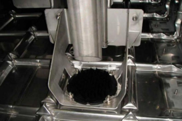
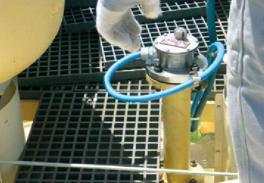
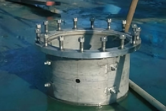
Isolating valve and float inspection chamber
There is a 300 mm gate valve, bolted to the top of the float well, that allows the gauge head to be isolated for maintenance.
An inspection chamber constructed of stainless steel is mounted above the isolating valve to allow access to the float and connection of the float recovery tools.
Maintenance
The level gauge system must be operated at regular intervals to ensure that the system is available in the event of any failure of the primary CTMS.
The housed reading difference between the level gauge system and the CTMS should be recorded at each operation. It is recommended that spare key components are carried.
Read also: Mastering LNG Measurement – Essential Practices and Operational Insights
The gauge head is sealed with locking wire and lead seals by the Classification Society and it is important to avoid damaging them. In the event of the seals being damaged or broken, arrangements should be made for a Class surveyor to check and re-seal the gauges.
When the gauges are not in use, the float must be raised and secured.
Tape breakage
In the event of tape breakage, notify the company or a manager because maintenance that requires the opening of a level gauge demands the attendance of a Class surveyor to oversee the re-calibration and then seal the gauge.
Detailed instructions for the recovery and replacement of the float assembly/tape, using the float recovery equipment (magnetic link float), will be included in the operating manual.
Renewal of tape
Tape length must always suit the tensator spring range and not the individual tank height measurements.
| Gauge Head Range | Tape Length |
| Up to 21 m (70 ft) | 21,2 m (70 ft) |
| Over 41,5 and up to 44,2 m (145 ft) | 45,1 m (148 ft) |
| Over 44 m and up to 54 m (145-175) | 54,2 m (175 ft) |
The springs can be extremely dangerous if they are not kept under control.
Tape can be renewed at any time provided it is permissible to release the small volume of vapour within the gauge head and inspection housing. If the tape has broken and the float is at the tank bottom or at the liquid level, it may be possible to retrieve the float without the need for anyone to enter the cargo tank.
The example that follows describes the tape renewal of a Whessoe system:
- close the isolation valve;
- remove the covers from the inspection housing and the gauge head;
- remove the split pins and washers from the tape and storage drum shafts and then remove both drums together from their shafts. Remove the damaged tape from the drum;
- place the two drums on a flat surface, with the tape drum uppermost and the tensator spring drums below. Enter the end of the new tape through the rectangular hole in the tread of the tape drum and pass the nearest sprocket hole to the end of the tape over a hook that is under the tread of the tape drum;
- rotate the coil of new tape around the tape drum in a clockwise direction so that when the tape is pulled it will rotate the tape drum in a clockwise direction. Continue until all of the tape is wound onto the tape drum and secure the end with some self adhesive tape;
- replace drums onto their shafts, together with the washers and split pins;
- turn the tape drum clockwise two full turns and hold (the number of turns of the spring can be seen through viewing holes on the tape drum and on the power drum);
- remove the binding from the tape and remove two wraps of approximately 1,3 m (4 ft) of tape from the tape drum.
It is important that you do not rotate the tape drum to remove the two wraps of tape.
- pass the tape over the sprocket and under the tape retainer. Pull the tape from the sprocket down through the mounting flange and into the inspection housing;
- attach the magnetic float recovery link to the tape. This is a lead weight with three magnets and tape clamp, usually found in the spares box. The attachment of the magnetic float recovery link is similar to the attachment of the tape to the plunger shaft assembly;
- replace the covers on the inspection hatch and gauge head;
- using the crank handle, lift the float recovery link off of the closure valve and hold;
- open the 10° isolation valve. Carefully let the float recovery link descend into the tank by holding the crank handle to support the weight and control the rate of descent.
When the float recovery link has secured itself to the pick-up plate on the float, the extra weight will be noticeable. Very carefully crank up the float until it is in the inspection housing. Care must be taken to get the float well up into inspection housing to keep it clear of the isolation valve. Note that the top of the lead weight on the float recovery link will not pass through the gauge head mounting flange.
- close the 10° isolation valve and remove the cover from the inspection housing;
- remove the main cover from the gauge head. Maintain a firm hold of the tape, and remove the float recovery link (returning it to spares box) and then fit the float to the tape with two screws;
- raise the float to the stowed position;
- adjust the counter as previously described;
- adjust the tape retainer so that there is a 0,5/0,75 mm gap between the tape and the retainer;
- replace the gauge head main cover and replace the cover on the inspection hatch.
The above is for example only. Manufacturer’s instructions should always be followed for the specific system used.
Precautions when using float level gauges:
- never leave a float level gauge on the liquid when it is not in use;
- when stowed, check the automatic lock is in place and the stowed reading is as expected.
- close the gate valve when the level gauge is stowed.
Capacitance type
This type of device operates using the variation, or electrical capacitance, between two probes when a liquid level changes. This is based on a coaxial sensor installed within the tank. The sensor is constructed of individual segments where the number of segments varies according to the height of the tank. As the liquid level in the tank changes the segment’s capacitance varies, generating a linear variation in each input sensing channel.
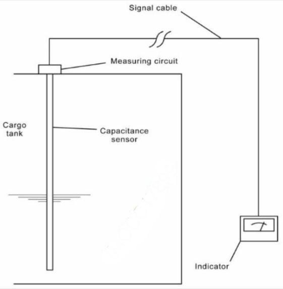
The level within the tank is determined by detecting the number of immersed segments, where the height of each segment (or partially immersed segment) is known.
Radar type
The electronic box generates and transmits radar waves into the cone antenna, which provides a smooth transition for the waves into the still pipe. Because the still pipe guides the radar waves very little signal energy is lost, which results in a strong echo from the liquid surface.
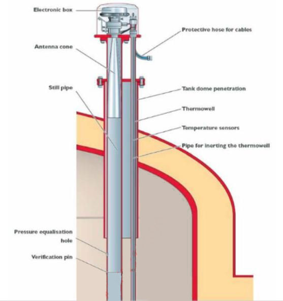
The tank radar system is based on the same principle as the ship radar. If the speed of the radar waves is known, the time needed by the signal to reach the cargo liquid level, bounce back and be picked up by the antenna can be accurately measured.
Together with the pressure sensor signal and the signals of the various temperature sensors at different levels in the tank, the tank ullage signal is sent to the CCR (cargo control room), via an intrinsically safe circuit. Using these parameters, the cargo volume can be calculated.
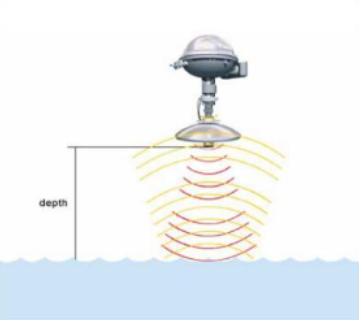
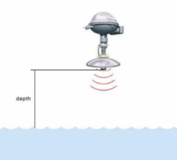
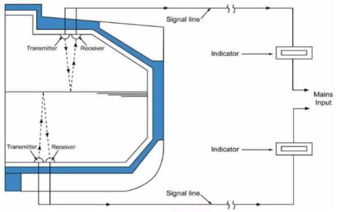
Ultrasonic gauge
An ultrasonic level gauge operates in a similar manner to an echo sounder, where the time taken for a sound wave to be reflected back through the liquid is measured and then used to calculate the liquid level.
Figure 16 shows the principle of the ultrasonic gauge.
All of these devices are classed as “closed” devices as, under normal circumstances, no cargo will be released during measurement.