Bunker Manifold Specifications are crucial for ensuring safe and efficient fuel transfer in marine operations. These specifications detail the essential components, such as fittings, reducers, and spool pieces, which must meet stringent safety standards. Proper design and arrangement of bunker manifolds play a vital role in preventing spills and leaks during transfers. Additionally, considerations for the size and location of the manifold help optimize operational efficiency.
Adhering to these specifications minimizes risks and enhances the reliability of the bunkering process, making it vital for maritime safety and environmental protection. Ultimately, well-defined bunker manifold specifications contribute to smoother and safer fuel transfers in the marine industry.
Manifold Specification and Fittings
Manifold Flanges. It is recommended that the gas carrier should have manifold flanges, as specified in either Understanding Liquefied Gas Manifolds – Size Categories, Positioning, and Specific Designs for LPG & LNG“LPG manifold size and horizontal distance”, on each side of the ship.
Further, the manifold Ranges should:
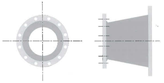
- Be «welded neck» type.
- Be «raised face» type.
- Conform to ASME B16.5 (Reference 11) pressure class 150 or 300.
- Be vertically aligned with the ship’s vertical axis.
- All be in line with the ship’s horizontal axis.
Presentation Flang
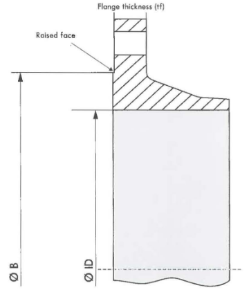
Presentation flanges should comply with the requirements for flanges in the manifold area. Particular attention should be paid to ensure that the presentation flange dimensions and face finish conforms to ASME B16.5 (Reference 11). As an example of some of the features to check for on a DN400/dass 150 Range are provided below with the relevant ASME Bl6.5 reference:
- 6.4.1: Raised face – 2 mm (Over and above Range thickness).
- 6.4.5.3: Raised face finish – Serrated concentric or serrated spiral finish.
- 6.4.5.3: Raised face finish – Average roughness 3,2 μm to 6,3 μm.
- Table 9: ∅ ID – 387 mm.
- Table 4: ∅ B – 469,9 mm.
- Table 9: Minimum thickness of flange (tf) – 35,0 mm.
- Table 9: Outside diameter – 595 mm.
Marking of Manifolds. It is recommended that the cargo manifold should be permanently and dearly marked, at a suitable location, with its designed safe working loads. The Ship to Ship (STS) Preparation and Manifold Connection for Transfer Operationmanifold arrangement should be marked on the ship side shell.
Distance Pieces. It is recommended that the length of distance pieces should be kept to a minimum and comply with distance «C» shown in Key Considerations for Manifold Design – Load Calculation Assumptions, Deck Protection, and Material Selection“Distance «C»”. Further, the length of the distance pieces should be adequate to provide sufficient room for:
- Ensuring that sufficient space is available for bolt withdrawal from the distance piece/reducer flanges. A minimum of 200 mm should be allowed for this purpose on each flange.
- Placing the manifold support bracket.
- Locating other line connections, including drain lines, pressure relief lines and pressure gauges that may be required by owners. Such lines, when incorporated, should not be fitted outboard of the manifold support.
- Length of cargo strainer.
Reducers and Spool Pieces
It is recommended that reducers and spool pieces should conform with the requirements of Key Considerations for Manifold Design – Load Calculation Assumptions, Deck Protection, and Material Selection“Understanding Calculation Assumptions in Manifolds” The use of a spool piece or reducer is recommended to protect the manifold flange from damage. It is typically significantly more difficult to repair a distance piece, so connecting directly to the manifold flange should be avoided.
If necessary, reducers and spool pieces should be fitted with a lifting lug. This lifting lug should be placed as near as possible to the centre of gravity and at a location that will not interfere with either the operation of the quick connect/disconnect coupler (QC/DC) or with the bolting of flanges.
If the reducer or spool piece flange connection is a solid flange without bolt holes, it is recommended that it should be provided with a blank flange that uses QC/DC fittings for securing the blank on completion of cargo transfer.
The required reducer or spool piece should be bolted directly to the outboard end of the distance piece. It is recommended that no more than one reducer or spool piece should be bolted to the distance piece. This is because, if more than one reducer is fitted, the design criteria defined in Key Considerations for Manifold Design – Load Calculation Assumptions, Deck Protection, and Material Selection“Understanding Calculation Assumptions in Manifolds” could be exceeded.
For LPG carriers, a recommended list of reducers and spool pieces is provided below in Table 1.
| Table 1. Suggested LPG reducers | ||||||
|---|---|---|---|---|---|---|
| Manifold Diameter (DN) (mm) | Reducers and Spool Pieces (DN) (mm) | |||||
| 100 | 100 × 150 only for vapour connectionsx | 100 × 100 only for vapour connectionsx | 100 × 75 only for vapour connectionsx | – | – | – |
| 150 | 150 × 200 | 150 × 150 | 150 × 100 only for vapour connectionsx | 150 × 75 only for vapour connectionsx | – | – |
| 200 | 200 × 250 | 200 × 200 | 200 × 150 | 200 × 100 only for vapour connectionsx | – | – |
| 250 | 250 × 300 | 250 × 250 | 250 × 200 | 250 × 150 | – | – |
| 300 | 300 × 400 | 300 × 350 | 300 × 300 | 300 × 250 | 300 × 200 | 300 × 150 |
| 350 | 350 × 400 | 350 × 300 | 350 × 250 | 350 × 200 | – | – |
| 400 | 400 × 400 | 400 × 350 | 400 × 300 | 400 × 250 | 400 × 200 | – |
Reducers and spool pieces for LNG carriers should be carried in accordance with the requirements of the trade.
Vessels engaged in LNG Ship-to-Ship Transfer Processship to ship transfer (STS) operations should refer additionally to the latest version of «Ship to Ship Transfer Guide for Petroleum, Chemicals and Liquefied Gases» (Reference 17), «The Safe Transfer of Liquefied Gos in on Offshore Environment» (Reference 18) and «Ship to Ship Service Provider Manogement» (Reference 19).
It is recommended that use of «cranked» or offset reducers, «Y» pieces, or additional spool pieces should be avoided unless sufficient engineering studies have been carried out that support safe use. If such equipment is used, certificates that indicate suitability should be available. The orientation of flange bolt holes should be as shown in Figure 2.
It is recommended that blank flanges fitted should be designed to the same pressure rating as the flange it is connected to. Further, blank flanges should be hinged or fitted with handles and a local lifting device, if necessary, to facilitate manual handling.
Additional Requirements
Water and oth er Connections. If drinking water or other similar connections are fitted, these should be placed in the manifold area at an appropriate distance from the cargo and bunker manifolds. These connections should be clearly marked.
Manifold Area Illumination. The levels of illumination in way of the manifold should conform to international or national standards established for working areas. Typically, these would require a light level of not less than 100 lux when measured on a parallel with, and 1 metre above, the deck. It is recommended that this illuminated area should extend over the ship side to the waterline in order to provide illumination for handling hoses at sea berths.
Read also: Ship/Shore Interface in Gas trading
Lifting Equipment and Cargo Hose Support. It is recommended that lifting equipment fitted to serve the cargo manifold area should be designed so as to be able to achieve its safe working load (SWL) along the full length of the cargo, Key Considerations for Manifold Design – Load Calculation Assumptions, Deck Protection, and Material Selectionbunkering and service manifolds and across the breadth from over the ship’s side to the manifolds.
For floating hose handling, the SWL of the lifting equipment should take into account the potential for shock loading during such handling. It is recommended that where cargo hose saddles are used they should have an SWL sufficient for their intended purpose.
Typically, an LPG cargo hose saddle will be formed from a curved plate or pipe section fitted at the ship’s side. It is recommended that the top of the hose saddle should not be higher than the bottom of the largest presentation flange that can be used by the ship.
Some designs of LNG cargo hose saddles or targeting devices require ship side railings to be removable or collapsible. It is considered that such a design introduces an additional hazard that should be avoided where possible.
Typically, LNG carriers in category B6 and B7 may be fitted with a simple davit to handle reducers or spool pieces. Where practicable, a cradle arrangement may usefully be provided at the manifold a rea to store spool pieces/reducers.
LPG Vessels Involved in Floating Hose Transfers
It is recommended that LPG carriers involved in floating hose transfers should be fitted with the following to assist with hoisting and hanging off hoses:
- One closed fairlead with a clear opening of appropriate size should be provided at the ship’s side, in the manifold area, for hose chains and hose hoisting. It should have a working load appropriate to the highest loads expected (including shock loads).
- One cruciform bollard should be placed in the deck area between the manifold and the ship’s side, allowing dear area for safe access.
- Deck rings or lugs of 15 tonnes SWL should be fitted on the deck inboard of the Fairlead and approximately 2 metres forward and 2 metres aft from the centre line of the Fairlead.
Access and Exits from the Manifold Area. Safe access is to be provided for the connecting and disconnecting of arms/hoses. It is recommended that there should be two independent means of exit for personnel from the manifold area to enable evacuation in the event of on emergency.
Access during Cargo Transfer. During cargo transfer operations, it is recommended that the need for personnel to access the manifold area should be limited to a minimum through good design.
Accordingly, it is suggested that the design process should consider the following:
- Placing manifold temperature and pressure indicators outside, but in the vicinity of, the manifold area.
- Allowing for the operation of valves required for line displacement and cool-down from outside the manifold area.
- Placing additional ESD buttons outside, but in the vicinity of, the manifold area.
- Avoiding the placing of any telephone booth or similar room within the manifold area.
- Creating a layout that provides on unobstructed view to persons standing outside the manifold area, including the angle of cargo lines and other piping structures.
- Placing dosed-circuit television (CCTV) in an optimal position to cover the manifold connections and valves.
Bunker Manifolds
This section provides recommendations for oil bunker, LNG bunker, and other connections. Owners may choose to fit oil bunker connections, LNG bunker connections or both oil and LNG bunker connections.
It is recognised that small gas carriers (Cat A1/A2 and B1/B2) may not be able to comply with all of the recommendations in this section, but to the extent possible it is anticipated that they will endeavour to do so and, where appropriate, otherwise follow the spirit of such recommendations.
Number and Arrangement
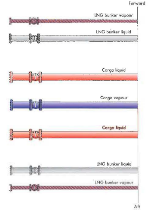
It is recommended that bunker manifolds should be provided forward and aft of the cargo manifolds, on both sides of the ship. If only one bunker manifold is provided, this should be located aft of the cargo manifold on both sides of the ship. Where LNG bunker manifolds are fitted, it is recommended that provision is made for a liquid connection and a vapour connection of the same size.
Where an LNG bunker manifold is placed forward of the cargo manifold, the LNG vapour manifold should be forward of the LNG liquid line and, where an LNG bunker manifold is placed aft of the cargo manifold, the LNG vapour manifold should be aft of the LNG liquid line.
Size and Location of Bunker Manifold
It is recommended that the size and spa cing of the bunker manifold should be as specified in Table 3. Spacing is measured from the centre of the presentation flanges.
| Table 3. Size and spacing of bunker flange | |||
|---|---|---|---|
| Category | Manifold Diameter – DN (mm) | Minimum Distance from Cargo Manifold (m) | |
| LPG | A1, A2, A3, A4 | 150 | 1,5 |
| A5, A6, A7 | 200 | 2,0 | |
| LNG | B1, B2, B3, B4 | 150 | 2,0 |
| B5, B6, B7 | 200 | 2,0 | |
It is recommended that the bunker connections should be located near the cargo manifold and that the base of the bunker connection should be at the same height as the base of the cargo connections. Presentation flanges should be aligned with the cargo manifold presentation flanges. Flanges, reducers and spool pieces should be fitted in accordance with ASME B16.5 and should be of pressure class 150 or 300.
Reducers and Spool Places for Bunkering
The following reducers/spool pieces should be provided for bunkering.
| Table 4. Reducers and spool pieces for bunker line | |||
|---|---|---|---|
| Category | Manifold Diameter – DN (mm) | Reducers/Spool Pieces – DN (mm) | |
| LPG | A1, A2, A3 , A4 | 150 | 150 × 150/150 × 200 |
| A5, A6, A7 | 200 | 200 × 150/200 × 200/200 × 250 | |
| LNG | B1, B2, B3, B4 | 150 | 150 × 150/150 × 200 |
| B5, B6, B7 | 200 | 200 × 150/200 × 200/200 × 250 | |
LNG bunkering will typically require a complete additional set of reducers/spool pieces for vapour connections. Typically, the material used to construct oil bunker reducers/spool pieces is different to LNG bunker reducers/spool pieces. Bunkering reducers/spool pieces should be clearly marked to indicate whether they are suitable for use with fuel oil or LNG bunkers.
Strength. It is recommended that the bunker manifold support, distance pieces, flanges, reducers and spool pieces should be designed according to Key Considerations for Manifold Design – Load Calculation Assumptions, Deck Protection, and Material Selection“Understanding Calculation Assumptions in Manifolds”.
Oil Spifl Containment. It is recommended that the fuel oil bunker connections should be provided with a separate drip tray that is segregated from the LNG/LPG drip trays.
LNG Spill Containment and Protection. It is recommended that LNG bunker connections should be provided with the same protection as recommended for LNG cargo connections (Key Considerations for Manifold Design – Load Calculation Assumptions, Deck Protection, and Material Selectionsee “Understanding Calculation Assumptions in Manifolds”).
Oil Bunker Hose Saddle. It is recommended that fuel oil bunker connections should be provided with a suitable hose saddle. For LNG carriers, it is suggested that the design of the saddle should consider the requirements of LNG STS operations and/or targeting methods.
It is considered that collapsing or removing hose saddles introduces an additional hazard that should be avoided where possible. However, it is recognised that some types of LNG hose saddles or targeting systems may require hose saddles to be removable or collapsible.
Other Connedions. It is recommended that filling connections for nitrogen, lubricating oil and fresh water should be located in close proximity to the cargo and bunker manifolds on both the port and starboard sides.