Get ready for a seamless ship-to-ship (STS) transfer operation on LNG carriers with our detailed preparation guide. Learn about essential safety protocols, necessary equipment, step-by-step procedures, and best practices to ensure efficient and safe LNG transfer operations between vessels.
Optimize your ship-to-ship transfer process with expert insights and comprehensive preparation tips.
Ship to Ship (STS) Preparation and Manifold Connection
Reference: SIGTTO “LNG Shipping Suggested Competency Standards”, Sections:
1 Have an awareness of safety procedures. STS (LNG) safety checklist:
- purpose;
- SIGTTO checklist.
2 Know and understand safety procedures. STS (LNG) safety checklist:
- possible additional ship specific requirements;
- content and agenda for pre-load and discharge meetings;
- purpose.
3 Know and understand manifold requirements prior to connection:
- STS hoses and equipment:
- hose saddles;
- hose couplings, fittings, Y places;
- HPUs;
- MLA (see Comprehensive Guide to Ship and Shore Preparation and Manifold Connection for LNG Cargo Operations“Marine loading arms”).
4 Have an awareness of STS hose connections and equipment:
- type and construction – safe operating parameters (i. e. transfer rates, pressures, etc.);
- purpose of safety devices;
- handling procedures;
- emergency breakout operation;
- cargo transfer hose recovery.
5 Know and understand STS hose connections and equipment:
- type and construction – safe operating parameters;
- purpose of safety devices;
- handling procedures;
- emergency breakout operation;
- cargo transfer hose recovery.
6 Awareness of ship to ship specific emergency shutdown systems:
- STS emergency shutdown system;
- STS vessel separation detection systems;
- STS emergency release systems;
- STS hose fall arrest system.
7 Know and understand ship to ship specific emergency shutdown systems:
- STS emergency shutdown system;
- STS vessel separation detection systems;
- STS emergency release systems;
- STS hose fall arrest system.
Ship to ship (STS) operations will occur for a variety of commercial and/or operational reasons. It is important to be aware that there are a variety of operations, depending on ship type and location.
However, the principle of ensuring that operations are planned and carefully prepared apply to all STS operations.
Safety procedures
The STS (LNG) safety checklists are similar in format to the Ship/Shore Safety Checklist but contain specific details that relate to Ship to Ship Bunkering Operations of the Liquefied Natural GasSTS operations. The STS checklists and useful guidance are found in Appendix E: Operational/safety checklists in the “Ship to Ship Transfer Guide for Petroleum, Chemicals and Liquefied Gases” (the STS Transfer Guide), published by SIGTTO, OCIMF, ICS and CDI.
There are five “at sea” STS checklists. These are:
| STS Safety Checklists | |
|---|---|
| At sea | In port |
| Checklist 1 – Pre-fixture information (for each ship) | Checklist 6 – A pre-transfer checklist |
| Checklist 2 – Before operations commence | Checklist 6a – Check during transfer |
| Checklist 3 – Before run-in and mooring | |
| Checklist 4 – Before cargo transfer | |
| Checklist 5 – Before unmooring | |
Pre-operations
Prior to arrival, a pre-fixture information checklist (Checklist 1) will be completed by both ships and returned to all parties. This will allow the compatibility process to be completed.
Once both ships have been accepted and scheduled for operations, the order of events is typically as follows:
- checklist 1 is exchanged between parties – this confirms that the two ships are compatible and will be able to load/discharge respectively. This may include:
- the size and dimensions of the two ships;
- the mooring arrangements and details of the ship’s side;
- maximum heights of manifolds, equipment, etc.;
- stability considerations;
- crane SWL and outreach, including certification for personnel transfer;
- experience and training of personnel on board.
- a plan of the operations, including mooring plans, are sent to respective parties;
- after any feedback a final joint plan of operations is agreed;
- weather forecasts are checked for the duration of the operation.
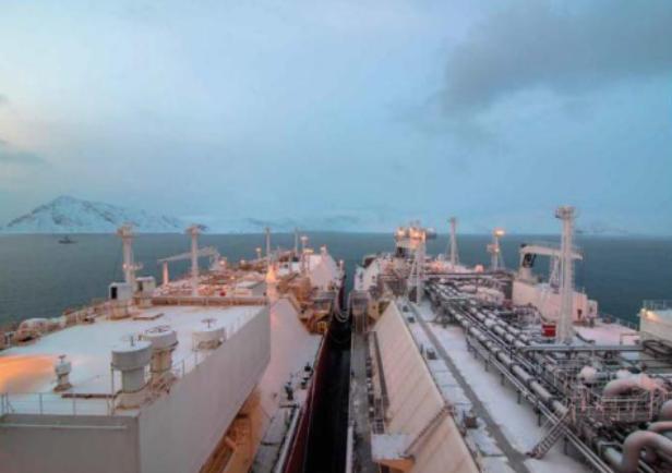
The following generally applies after the final plan of operations is agreed:
- the receiving ship will be at anchor to allow the supply and rigging of all the necessary equipment. There are two types of STS equipment – 8 inch and 10 inch;
- the receiving ship will remain at anchor or may have to move to the designated transfer location, ready to receive the lightering ship;
- the manoeuvring ship will depend on the two ships involved in the STS. It may be the lightering ship and the ships may be manoeuvred with or without the assistance of tugs;
- an STS mooring master is generally on the lightering ship;
- an STS Superintendent will be on board the receiving ship to facilitate communications and ensure safe rigging of STS equipment;
- the primary fenders will be rigged on the receiving ship;
- the secondary fenders will be rigged on the lightering ship.
The deployment of fenders and mooring process will be operationally specific.
Before commencement of operations
Before operations commence checklist (Checklist 2) is jointly completed by each ship. The joint declaration should not be signed until both parties have checked and accepted their assigned responsibilities. The organisers of the STS should notify the local authorities of their intentions and obtain any necessary permissions.
It is usual for additional personnel to join the ships to assist the operation.
For example, an STS superintendent and mooring master.
If the pilot and/or mooring master have any doubts concerning the rendezvous position, due to the weather being experienced or forecast for the time of the operation, they must liaise with both Masters and, if necessary, postpone the operation.
Before run-in and mooring
Checklist 3 should be filled prior to manoeuvring and mooring:
- berthing will normally be conducted with lightering ship at anchor, equipped with STS transhipment equipment and fender guards. The lightering ship will liaise directly with the receiving ship;
- the complete mooring sequence is to be indicated on the final STS Mooring Plan issued and approved by both Masters.
The prevailing environmental conditions should be taken into consideration as these will determine the type and number of fenders and the type of mooring procedure to be used. All parties should be in agreement that conditions are suitable for mooring and cargo transfer before the operation takes place.
Read also: Ship-to-ship LNG transfer operations
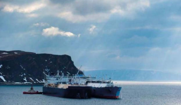
The most successful method of mooring is with both ships underway. One ship, preferably the larger, maintains steerage way on a constant heading as requested by the manoeuvring ship, usually with the wind and sea dead ahead. The manoeuvring ship then comes alongside.
Normally, the lightering ship maintains course and speed. Successful operations on other tankers have taken place with one ship at anchor in fine weather conditions. This is not too difficult if there is an appreciable current and a steady wind from the same direction. Otherwise, tug assistance may be necessary. Mooring should be rapid, efficient and achieved through good planning, including a pre-toolbox talk with all members of the respective mooring parties.
In general, the following points should be noted:
- the wind and sea should be ahead or nearly ahead;
- the angle of approach should not be excessive;
- the two ships should make parallel contact at the same speed with no astern movement being necessary or used;
- the manoeuvring ship should position her manifold in line with that of the constant heading ship and match the speed as near as possible;
- effective communications should be maintained throughout.
All parties should be prepared to abort if necessary. The COLREGS must be complied with at all times.
On completion of mooring, the constant heading ship will proceed to an anchoring position previously agreed. The manoeuvring ship will have its engines stopped and rudder amidships or angled towards the constant heading ship. The constant heading ship should use the anchor on the opposite side to that on which the other ship is berthed. Signals should be displayed and navigation warnings issued as appropriate. From the time that the manoeuvring ship is all fast alongside, to the time the constant heading ship is anchored, the constant heading ship directs the navigation of the two ships.
Contact is then made by the manoeuvring ship, reducing the distance between the two ships by rudder movements, until contact is made by the primary fenders. Engine speeds of both ships should be reduced together.
Before cargo transfer
Checklist 4 should be completed before cargo transfer. The purpose of the STS pre-transfer meeting is to ensure that the persons in charge of cargo operations on board both ships understand and are in agreement regarding how the LNG transfer operation will proceed and to ensure safe cargo transfer practices are followed.
The pre-transfer meeting shall include, as a minimum, discussion of the following:
- safety issues pertinent to the discharge;
- potential weather considerations;
- communications, including primary and secondary means;
- CTMS and all meter readings shall be confirmed;
- cargo specification including temperatures and pressures;
- ordered flow rates, nominations and potential changes;
- maximum flow rates;
- minimum and maximum tank vapour pressure (both ships);
- maximum LNG transfer pressure;
- ramp-up considerations including rates;
- ramp-down considerations including rates;
- identification of measures to be taken in the event of an incident;
- the safety checklists (see below);
- notice required for main engines;
- schedule of persons in charge.
Ship specific requirements should be discussed at the pre-transfer meeting. This should include, as applicable, any requirements due to length of the ships involved, specific personnel transfer requirements and the applicability of the shipboard STS deluge pool.
For further information on the content and agenda for the pre-load and Main Procedures and Best Practices of Liquefied Gas Discharge from LNG Carriersdischarge meetings, refer to “ISGOTT” and the “Ship to Ship Transfer Guide for Petroleum, Chemicals and Liquefied Gases”.
All equipment to be used should be thoroughly prepared and tested and all safety equipment should be checked and ready for use if required.
Cargo equipment to be tested and confirmed as fully operational includes:
- ventilation of compressor, pump and control room;
- gas detection systems;
- emergency shut down system;
- pressure and temperature control units;
- cargo tanks (to be cooled, if necessary);
- manifolds (to be securely blanked);
- cargo hose reducers;
- hose purging equipment.
Additionally confirm:
- the ship’s separation and detection system is tested;
- the ESDS is tested;
- various tests on the HPU have been carried out;
- hoses have been pressure tested to 5 bar;
- prior to commencement of operations, that ERC has been placed in operational mode.
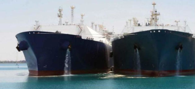
Safety precautions to be observed include:
- fire main tested and kept under pressure;
- water spray system tested and ready;
- manifold water curtain;
- two additional fire hoses connected near the manifold and ready for use;
- dry powder system ready;
- all access doors to the accommodation to be kept closed at all times during transfer;
- switching accommodation A/C to full recirculation;
- impressed current cathodic protection system, if fitted, to be switched off at least 3 hours before transfer.
A full visual inspection of all reducers, hoses and other cargo equipment must be carried out. For details of the cargo transfer procedure, including cooldown, warm-up and transfer, read below.
Manifold requirements and ship to ship hose connections and equipment
As a mini mum, the fol lowing equipment will be provided for the operation:
- suitable flexible cryogenically rated transfer hoses, reducers, saddles and Y-pieces;
- one set of cables to link the ESD systems (note, the ESD systems must be compatible);
- a means to permit the safe transfer of personnel between ships;
- connection to both the cargo and emergency switchboards with one set of electric cables to allow the supply of electrical power from one ship to another for the operation of hydraulic power packs and instrumentation;
- fenders of the required type and size;
- hydraulic power unit (HPU) and hoses;
- emergency release coupling (ERC);
- ship separation detection and trip system.
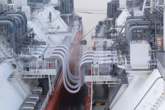
Saddles. The purpose of the saddles is to hold the weight of the hoses over the railing and prevent short radius bending. It incorporates a fall arrestor and retraction system to control the fall of the hose in the event of emergency release. Saddles usually have a “ballast” compartment and a water-glycol mixture should be used in cold weather. The saddles should not touch the railings of the ship.
Hoses, couplings, fittings, Y-pieces, HPUs
Hose couplings, fittings and Y-pieces, etc arrive with the other STS equipment. Equipment is received on board using the ship crane from another ship/barge, along with the other STS equipment.
Hoses are suitably rated for operation and should meet the requirements of the IGC Code. Hoses have a lifting saddle to allow correct movement using the ship’s crane, preventing the bend radius of the hose being exceeded. Note that hoses have a bending radius limit but not the same movement operational envelopes as MLAs.
Connection is performed by lifting the hose vertically to remove twists. Suitable reducers should be secured in position, with gaskets fitted. On each of the reducers, an appropriate ERC is then installed (see the following page for more details on ERC). As the hose flange connections are completed, the hose should be laid out over the saddle and ship’s side. A lifting strop us then used to secure the hose against the ship side, until connection between the two ships is made.
Hoses will have safe operation parameters. These include transfer rates and maximum pressures, usually detailed on a certificate from the Classification Society. Records of testing and inspection should be maintained. Hoses should be stored as per manufacturer’s recommendations.
A hydraulic power unit (HPU) is a dedicated unit for STS operations. It provides hydraulics for emergency release and ship separation and detection system that will activate ESD1/ESD2. The HPU is usually driven by the ship’s control air. Minimum pressure should be 6 bar. The control air should be dry.
Handling procedures
Handling should be accomplished carefully using the ship’s manifold cranes. The hoses are passed via the hose handling cranes and the use of a davit/ropes/buns to assist handling.
Each hose is connected to the ship’s manifold using the ship’s crane. The weight of the hose is supported by the saddle. They are designed so the saddle and manifold are at the same heights.
Cargo transfer hose recovery. This will vary according to the type and system fitted. Within the KLAW system (and other similar manufacturers), the retractor and ships crane/davit are using to bring the hose back on board.
Ship to ship specific emergency shutdown systems
Purpose of safety devices
The two primary safety devices are the emergency release coupling (ERC) and the ship separation and detection system:
- the ERC is only on one ship and, if activated, it will trigger disconnection of the hoses;
- the ship separation and detection system are comprised of 2 weak links, of different lengths, between the two ships:
- the first, shorter link, will trigger the ESD1 if it breaks, stopping the cargo operation;
- the second, longer link, will trigger the ESD2 and ERC if it breaks, disconnecting the two ships. At this point, to avoid spillage and to avoid damage to hoses, the fall arrest system will control the fall of the hoses.
Activation will follow during emergency breakout. The hose fall arrest system is incorporated into the saddle arrangement.
Ship to Ship Transfer of Cargo
Reference: SIGTTO “LNG Shipping Suggested Competency Standards”, Sections:
1 Have an awareness of the procedures and equipment for STS transfer of cargo:
- Hose/MLA operating envelopes;
- Cool-down and Efficient Liquefied Natural Gas Tank Warming Procedureswarm up process;
- transfer rates;
- vapour management;
- communications;
- ESD link.
2 Know and understand the procedures and equipment for STS transfer of cargo:
- Hose/MLA operating envelopes;
- Cool-down and warm up process;
- transfer rates;
- vapour management;
- communications;
- ESD link.
Procedures and equipment for ship to ship transfer of cargo
For details of ship to ship transfer equipment, read above.
Cargo transfer can begin when the two Masters have ensured that all the pre-transfer checks and precautions have been completed and agreed. Both ships should be prepared to disconnect and unmoor at short notice should anything go wrong.
During transfer, ballast operations should be performed to keep the trim and list of both ships constant. Listing of either ship should be avoided except for proper tank draining. Checks should also be kept on the weather, traffic in the area and that all safety equipment is still in a state of readiness.
The most common method of transfer is while the two ships are at anchor. Transfer can also take place while the two ships are underway, although this depends on there being adequate sea room, traffic conditions and the availability of large diameter, high absorption fenders.
Underway transfer – After completion of mooring, the constant heading ship maintains steerage way and the manoeuvring ship adjusts its engine speed and rudder angle to minimise the towing load on the moorings. The course and speed should be agreed by the two Masters and this should result in the minimum movement between the two ships. The Master of the constant heading ship directs the navigation and safety of the two ships.
Drifting transfer – This should only be attempted in ideal conditions (i. e. ships stopped, calm waters).
Communications. Communications are usually between the two ship’s using UHF handheld radios, VHF radios and the “hotline”. Whichever methods are used, these should be tested before transfer commences.
Cooldown and warm-up process
Assuming the receiving ship’s tanks are in a cold (ready to load) condition, cool down will commence at an agreed slow rate to cool down the hoses. This is usually from a spray pump. The time for finish of cooldown will be when the liquid lines on the receiving ship are at the required temperature and they can begin cargo transfer.
To assist the vaporisation, seawater is directed from fire hoses on both ships to the lower bend radius of the cargo hoses (which contain LNG).
For warming up, remaining LNG in the cargo hoses will vaporise when 5 bars is achieved at the manifold and the appropriate valves then open to release the pressure/liquid free of the hoses. This process is repeated until the hoses are liquid free.
The cargo hoses are then purged with nitrogen. When the atmosphere is < 50 % of LEL, the hoses can be disconnected. The hoses are disconnected first from the ship that does not have the ERC fitted.
Transfer rates. Transfer rates are agreed according to BOG management requirements. While hoses can handle high rates of transfer, the maximum transfer rate is dictated by the receiving ship’s BOG management. Rates are agreed and confirmed at the pre-transfer meeting (see above).
Vapour management
To manage excess BOG, gas burning will be allowed without restriction and the GCU will be utilised as necessary. This may not necessarily apply to STS with FSRUs.
It is important that both Masters understand each ship’s BOG burning capacities. Note that the overall vapour load during the Cooldown of Cargo System on the Liquefied Gas Carrierscooldown process can be reduced by pre-cooling liquid headers prior to mooring. However, the manifolds must be isolated by double block valves.
ESD link
The ship’s separation detection system, which will trigger the ESD1 and ESD2, is connected to the HPU. The HPU is then connected to the ERC.
The ESDS must be capable of being activated manually between the two ships and it is usually connected by a pneumatic (air hose) link. The ESDS is tested prior to commencing the operation. For more information, see above.
Completion of transfer
Before unmooring, all hoses should be liquid-free, purged, disconnected and manifolds securely blanked. After cargo transfer is completed, hoses and all other STS equipment are usually tested using manufacturer’s (SIL) recommendations. This may be done ashore.
Equipment has a safety integrity level (SIL), which is either the relative level of risk reduction provided by the safety function, or is a specified target level of risk reduction. SIL certification identifies all process hazards,estimates failure risks and determines how, if a failure occurs,it will fail safely.
The relevant authorities should be informed that transfer is complete.
Unmooring
Checklist 5 should be completed before unmooring. Under normal conditions this procedure will be carried out at anchor. However, if both Masters agree to it, unmooring can take place underway. Before unmooring begins, obstructions from the adjacent sides of both ships should be cleared and the sequence and timing of the event agreed and commenced at the request of the manoeuvring ship.
Mooring lines should be let go as agreed. Neither ship should, at this point, attempt to manoeuvre until their mid lengths are about two cables apart.