Liquefied Gas Manifolds are critical components in the shipping and handling of liquefied petroleum gas (LPG) and liquefied natural gas (LNG). These manifolds facilitate the safe and efficient transfer of gas during loading and unloading operations. They are designed to handle high-pressure conditions while ensuring minimal risk of leaks.
When considering manifold design, size categories play a vital role in determining compatibility with various vessel types. Proper positioning of the manifold is essential for optimal functionality and safety, often placed on the ship’s side or rear.
Introduction
Each type of manifold must meet stringent international regulations to guarantee safe operation. In LPG systems, the manifolds are tailored to manage specific pressures and temperatures unique to the gas. Similarly, LNG Marine Loading Arms and Manifold Draining, Purging and Disconnection ProcedureLNG manifolds have specialized adaptations to handle the cryogenic nature of the fuel. The choice of materials used in the construction of these manifolds is crucial for durability and resistance to corrosion. As advancements in technology continue, the design and efficiency of liquefied gas manifolds are expected to evolve, enhancing safety and operational performance in the maritime industry.
Scope
These recommendations are for liquefied petroleum gas (LPG) carriers and liquefied natural gas (LNG) carriers. For the purposes of this document, the term LPG carrier refers to liquefied gas cargoes carried between the temperature range of 0 °C to -104 °C. These recommendations do not apply to existing ships, and there is no suggestion that existing ships should be altered.
It is recognised that some new gas carrier designs may not be able to conform to all of the recommendations in this document, however, this document is intended to serve as a starting point with a view to minimising differences as much as possible.
Size Categories
For the purpose of this document: LPG carriers are divided into seven size categories that are based on cargo capacity.
| Table 1. LPG carrier categories | ||
|---|---|---|
| Category | LPG Cargo Capacity (m3) | |
| From | To | |
| A1 | – | 6 000 |
| A2 | 6 001 | 15 000 |
| A3 | 15 001 | 25 000 |
| A4 | 25 001 | 50 000 |
| A5 | 50 001 | 70 000 |
| A6 | 70 001 | 85 000 |
| A7 | 85 000+ | – |
LNG carriers are divided into seven size categories that are based on cargo capacity.
| Table 2. LNG carrier categories | ||
|---|---|---|
| Category | LNG Cargo Capacity (m3) | |
| From | To | |
| B1 | – | 6 000 |
| B2 | 6 001 | 15 000 |
| B3 | 15 001 | 25 000 |
| B4 | 25 001 | 50 000 |
| B5 | 50 001 | 70 000 |
| B6 | 70 001 | 200 000 |
| B7 | 200 000+ | – |
Manifold Position
To assist in the safe connection of a facility’s cargo transfer equipment, it is recommended that the location of liquid and vapour manifolds on a gas carrier should be harmonised as described in this part of the article.
Manifold – LPG
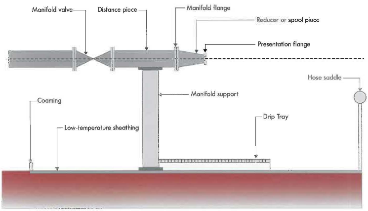
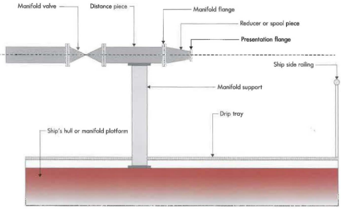
An example of a typical LPG carrier manifold is shown in Figure 1.
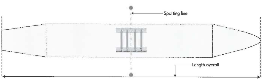
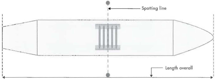
Centre of manifold – LPG. It is recommended that the longitudinal centre of the cargo manifold arrangement (spotting line) should be located at the middle of the ship’s length. Preferably, the centre of the arrangement should not be displaced, forward or aft of the mid -length, by more than 4 metres.
Manifold Strainers
The use of filters in the cargo manifold helps prevent debris from getting into the cargo tanks or shore tanks. Filters may be conical or basket type.
When using filters in the manifold, the pressure differential across the filter should be monitored to check for filter blockage. The ship and terminal should agree on a suitable method to monitor the pressure before commencing cargo operations.
Following points are recommended for cargo filters:
- Bi-directional filters to avoid the possibility of a wrong filter being used.
- The material of construction should be suitable for the intended cargo.
- Comply with ASME B31.3 (Reference 20).
- Max flow resistance should not exceed 0,5 Bar for a clean filter.
- Should be able to withstand the same design pressure as the manifold it is fitted to.
- Should be able to withstand a maximum pressure differential of at least 3 Bar.
For LNG, two types of liquid filters are typically used:
- Filter with a mesh size of ASTM 20 (nominal aperture of 0,84 mm).
- Filter with a mesh size of ASTM 60 (nominal aperture of 0,25 mm).
LPG carriers with pressurised tanks that are unable to comply with the above requirements should preferably ensure that the difference is reduced to a minimum.
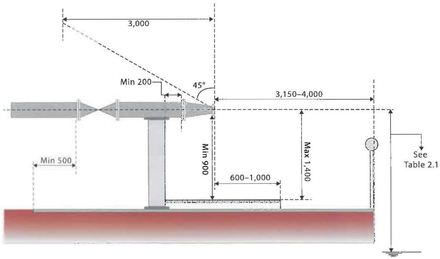
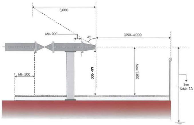
Distanse from ship’s side – LPG. It is recommended that the distance of presentation flanges inboard from the ship’s side should be between 3,15 metres and 4 metres (see Figure 3). Preferably, such flanges should be presented on the same fore and aft line.
For LPG Carriers in category A1 and A2, the minimum distance of presentation flanges inboard from the ship’s side may be reduced, but should preferably not be less than 2 metres.
The manifold area should be clear of any obstructions that may interfere with the automatic release of a marine loading arm (MLA) (see Figure 3). For guidance, 3 000 mm, measured above a 45 degree angle from the centre of the presentation flange, should typically be sufficient.
Height of manifold – LNG. The height of the presentation flange above the working platform is the distance between the bottom edge of the manifold presentation flange and the top of the working platform. It is recommended that this distance should not be less than 900 mm, to ensure sufficient clearance (see Figure 3). The distance should be measured using the largest presentation flange that can be used by the ship.
Further, to allow safe access to bolts, the height of the centre of the manifold, above the working platform, should preferably not be greater than 1 400 mm (see Figure 3). The recommended height, measured from the centre of the manifold flange to the water line , is provided in Table 3.
| Table 3. Height of manifold above water line | ||||
|---|---|---|---|---|
| Category | From (m3) | To (m3) | Not greater than (m) (at minimum operating draught) | Not less than (m) (of maximum operoting drought) |
| A1 | – | 6 000 | 10 | 2 |
| A2 | 6 001 | 15 000 | 10 | 2 |
| A3 | 15 001 | 25 000 | 12 | 4 |
| A4 | 25 001 | 50 000 | 16 | 6 |
| A5 | 50 001 | 70 000 | 16 | 6 |
| A6 | 70 001 | 85 000 | 18 | 8 |
| A7 | 85 001 | – | 18 | 8 |
Spacing and size – LPG. The recommended size of, and horizontal distance (H) between, manifolds is provided in Table 4.
| Table 4. LPG manifold size and horizontal distance | ||||
|---|---|---|---|---|
| LPG Category | Manifold Diameter (DN) | Horizontal Distance (H) | ||
| Liquid (mm) | Vapour (mm) | Minimum (m) | Maximum (m) | |
| A1 | 150 | 100 | 1,25 | 1,75 |
| A2 | 200 | 150 | 1,25 | 1,75 |
| A3 | 250 | 200 | 1,5 | 2,0 |
| A4 | 300 | 200 | 2,0 | 2,5 |
| A5 and A6 | 300/350 | 250 | 2,25 | 2,75 |
| A7 | 400 | 300 | 2,25 | 2,75 |
At exposed locations, targeting devices may need to be fitted to the manifold Range. Consideration should be given to allow for sufficient clearance, around the manifold Range, for such devices to be fitted.
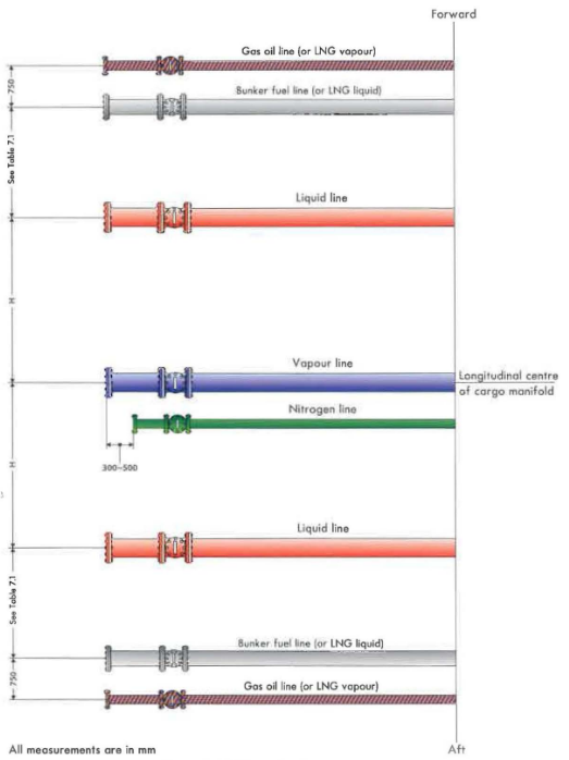
Arrangement – LPG. Two typical manifold arrangements for LPG carriers are shown in Figures 4 and 5.
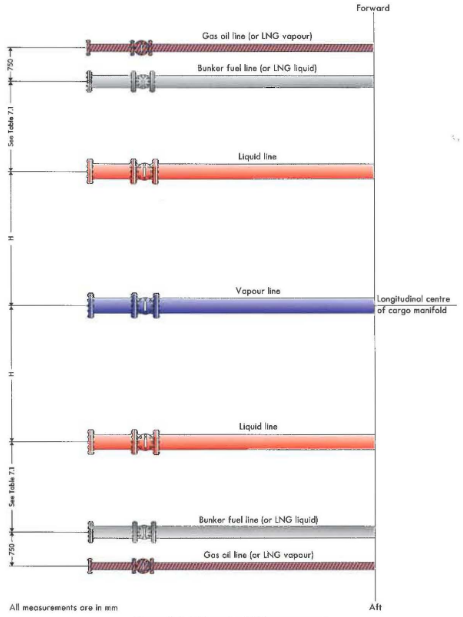
It is recommended that cargo liquid connections (L) should be placed on ei ther side of vapour connections (V). Depending on the size of the Terminal Operations for LNG or LPG Carrier after Arriving in PortLPG carrier, the configuration is either LVVL or LVL.
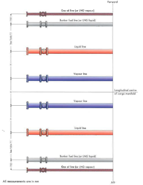
It is worth noting here that in Japanese terminals the arrangement «VLLV» is typically found . In addition, for small gas carriers with only one liquid line, the arrangement «VLV» is typically found as this provides better flexibility.
Depending upon design, bunker fuel or diesel fuel manifolds can be located forward or aft of each other. LNG Security Zones in LNG Bunkering: A Guide to Meaningful Protectionbunkering manifolds may need to be added in addition to, or in lieu of oil bunker manifolds, as per the ship owner’s preference. In any event, it is recommended that minimum spacing from the nearest cargo manifold should be maintained.
Manifold – LNG
An example of a typical LNG carrier manifold is shown in Figure 6.
Centre of manifold LNG. It is recommended that the longitudinal centre of the manifold arrangement (spotting line), should be located at the middle of the ship’s length. Preferably, the centre of the arrangement should not be displaced, forward or aft of the mid-length, by more than 5 metres.
LNG carriers with pressurised (Type C) or spherical tanks (Type B) that are unable to comply with above requirements, should preferably ensure that the difference is reduced to a minimum.
Distance from ship’s side – LNG. It is recommended that the distance of presentation flanges inboard from the ship’s side should be between 3,15 metres and 4 metres (see Figure 8). Preferably, such flanges should be presented on the same fore and oft line.
For LNG carriers in category B1 and B2, the minimum distance of presentation flanges inboard from the ship’s side may be reduced, but preferably should not be less than 2 metres.
The manifold area should be dear of any obstructions that may interfere with the automatic release of a marine loading arm (see Figure 8). For guidance, 3 000 mm, measured above a 45 degree angle from the centre of the presentation flange, should typically be sufficient.
Helght of manifold – LNG. The height of the presentation flange above the working platform is the distance between the bottom edge of the manifold presentation flange and the top of the working platform. It is recommended that this distance should not be less than 900 mm, to ensure sufficient clearance (see Figure 8). The distance should be measured using the largest presentation flange that can be used by the ship.
Read also: Comprehensive Guide to Ship and Shore Preparation and Manifold Connection for LNG Cargo Operations
Further, to allow safe access to bolts, the height of the centre of the manifold, above the working platform, should preferably not be greater than 1 400 mm (see Figure 8). When deciding the height of the manifold, consideration should also be given to Ship to Ship (STS) Preparation and Manifold Connection for Transfer Operationship to ship transfer (STS) requirements which may require the use of portable hose saddles.
The recommended height, measured from the centre of the manifold flange to the water line, is provided in Table 5.
| Table 5. Height of manifold above water line | ||||
|---|---|---|---|---|
| Category | From (m3) | To (m3) | Not greater than (m) (at minimum operating drought) | Not less than (m) (al maximum operating draught) |
| B1 | – | 6 000 | 12 | 4 |
| B2 | 6 001 | 15 000 | 16 | 6 |
| B3 | 15 001 | 25 000 | 18 | 8 |
| B4 | 25 001 | 50 000 | 20 | 10 |
| B5 | 50 001 | 70 000 | 22 | 12 |
| B6 | 70 001 | 200 000 | 22 | 14 |
| B7 | 200 000+ | – | 24 | 14 |
Spacing and size – LNG. The recommended size of, and honzontol distance (H) between, connections 1s provided in Table 6.
| Table 6. LNG manifold size and horizontal distance | ||||
|---|---|---|---|---|
| LNG Category | Manifold Diameter (DN) | Horizontal Distance (H) | ||
| Liquid (mm) | Vapour (mm) | Minimum (m) | Maximum (m) | |
| B1 | 150 | 150 | 1,5 | 2,0 |
| B2 | 200 | 200 | 1,5 | 2,0 |
| B3 | 250 | 250 | 2,0 | 2,5 |
| B4 | 300 | 300 | 2,5 | 3,0 |
| B5 | 300 | 300 | 2,5 | 3,0 |
| B6 | 400 | 400 | 3,0 | 3,5 |
| B7 | 400/500 | 400/500 | 3,5 | 4,0 |
At exposed locations, targeting devices may need to be fitted to the manifold flange. Consideration should be given to allow sufficient clearance, around the manifold Flange, for such devices to be fitted.
Arrangement – LNG. Two typical manifold arrangements for LNG carriers are shown in Figures 9 and 10.
Depending upon design, bunker fuel or diesel fuel manifolds can be located forward or aft of each other.
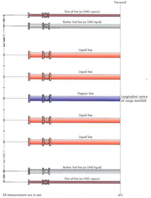
LNG bunkering manifolds may need to be added in addition to, or in lieu of oil bunker manifolds, as per the ship owner’s preference. In any event, it is recommended that minimum spacing from the nearest cargo manifold should be maintained.