Calculation Assumptions in Manifolds play a vital role in ensuring their effectiveness and safety. These assumptions include factors such as material properties, load distributions, and environmental conditions that impact the manifold’s performance. By understanding these key elements, engineers can design manifolds that are both efficient and durable, whether they are constructed from carbon steel or stainless steel.
Additionally, correct assumptions help in calculating the required support structures, enhancing overall reliability. Ultimately, thorough consideration of these assumptions leads to better decision-making in manifold design and application across various industries.
Deck Protection
The deck around the manifold area should be protected from the risk of cargo spillage by:
- being constructed from a suitable material (as specified in the IGC Code (Reference l));
- or (ii) sheathing made from a material that is compatible with low-temperature liquids (LNG and/or LPG, as applicable).
It is recommended that this protection should extend longitudinally for at least 1,5 metres beyond the outermost edge of the outermost cargo manifold flange. Further, this protection should extend transversely from the ship side to at least 0,5 metres inboard of the outermost manifold valve (emergency shutdown (ESD) valve). In addition, in the case of other transfer line layouts, the protection should extend over any other areas that may be subject to spillage.
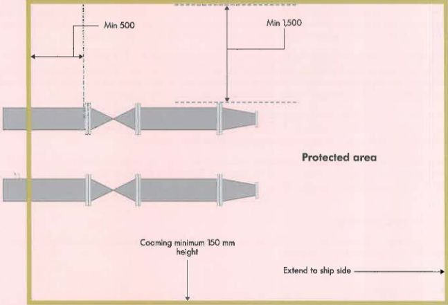
Coaming Requirements
It is recommended that to contain a leak from the cargo manifold, the protected area (shown in Figure 1) Tshould be provided with a coaming with a height of not less than 150 mm.
Drip Trays. The recommendations higher may be achieved by providing a suitable drip tray designed to give the same protected area and capacity. A drip tray should have a min imum depth of 300 mm. For LPG carriers, the protected area is typically achieved by a combination of a drip tray and a protected area (see Understanding Liquefied Gas Manifolds – Size Categories, Positioning, and Specific Designs for LPG & LN“LPG manifold distances (mm)”). On LNG carriers, o drip troy covering the entire protected area may be o more practical solution, as this may provide a platform suitable for both STS operation requirements and loading arm jocks (see Understanding Liquefied Gas Manifolds – Size Categories, Positioning, and Specific Designs for LPG & LNG“LNG manifold disfonces (mm)”).
Gratings. Manifold drip tray gratings should be of a material that is not adversely affected by spilled cargo. All manifold gratings should be secured to the drip tray structure to provide a firm, non-skid, working surface that is free from any protrusions that personnel may trip on, and would not interfere with operations.
The grating support structure and the drip tray structure should be designed with sufficient additional load bearing capacity to take the loading from the loading arm jacks. In the absence of any other requi rements, it is recommended that gratings should be designed ta withstand a load of 1 tonne per sq. metre. For LNG carriers, consideration should also be given to the load (including dynamic loading} from STS equipment.
It is recommended that the grating material is diss ipative or electrically conductive in accordance with the latest IEC Standard 60079-32 (Reference 2). The grating should be secured to the adjacent supporting structure by a method that ensures o positive earthing arrangement to the ship’s structure.
The grating material should also be resistant to mechanical damage from dropped objects in the manifold working area and to exposure to the marine environment. The grating should be removable in easily handled sections to permit access to the drip tray.
Drainage – LPG. For LPG carriers, it is recommended that the protected area and drip tray should be provided with means to drain off any water that may accumulate.
Drainage – LNG. For LNG carriers, it is recommended that the protected area should be provided with a drain line capable of leading a spill overboard. The drain line should be fitted with a valve that would be dosed during normal operation and which can be opened from a remote location.
The discharge from the line should point vertically downwards or otherwise so as not to deluge the jetty or its associated equipment with drained liquid. The discharge from the line should be in the manifold area so that the Volume measurement methods of LNG transferredLNG carrier’s hull is protected by the water curtain specified below.
Water Curtains for LNG Carriers. The hull of LNG carriers should be protected by a water curtain at the ship’s side that extends over at least the full length of the potential spillage area for ship to ship (STS) transfer using hoses, consideration should also be given to the provision of an effective water curtain or suitable screen. This is to protect the deck under the manifold platform.
Manifold Design
The recommendations in this section are provided for two types of material: carbon steel and stainless steel. The choice of material is usually dictated by the temperature of the product carried. Carbon steel may be used to construct fuel oil Understanding Liquefied Gas Manifolds – Size Categories, Positioning, and Specific Designs for LPG & LNGbunker manifolds. This may also be used to construct some types of LPG carrier manifolds. Stainless steel is typically used to construct LNG carrier, LPG carrier and LNG bunker manifolds.
Ensuring the integrity of the manifold design is typically addressed by specifying the:
- Pipe schedule.
- Allowable loads for the manifold support.
- Minimum mechanical properties of material used.
- Pressure rating of flanges, reducers and spool pieces.
Information on the pipe schedule, materials used , allowable loads used in the design of the support and pressure rating should be available on board and certified by a Classification Society. This information will assist in the ship personnel’s awareness of the limitations of the manifold design. This information will also allow engineering calculations to be carried out at a future date, if required under special circumstances.
The dimensions and characteristics of the manifold provided in this section should be considered by the General Arrangement of LNG Custody Transfer Systemtransfer system provider when carrying out the analysis of loads. Additional useful information may be found in the latest edition of the OCIMF document: «Design and Construction Specification for Marine Loading Arms» (Reference 3).
Carbon Steel Manifold
Pipe schedule. The minimum pipe schedule is recommended in Table 1.
| Table 1. Minimum pipe schedule | |||||||
|---|---|---|---|---|---|---|---|
| Connection Diameter (mm) | 100 | 150 | 200 | 250 | 300/350 | 400 | 500 |
| Schedule | XS | XS | STD | STD | STD | STD | STD |
Allowable loads for manifold support. For each connection, the minimum recommended allowable loads for the manifold support are provided in Table 2.
| Table 2. Allowable loads | |||||
|---|---|---|---|---|---|
| Connection Diameter (DN)(mm) | Fx (N) Lateral | Fy ext (N) Axial | Fz (N) Vertical | Mxz (Nm) | Mt (Nm) (torque moment) |
| 100 | 20 000 | 35 000 | 30 000 | 9 300 | 1 500 |
| 150 | 30 000 | 50 000 | 50 000 | 30 000 | 1 500 |
| 200 | 35 000 | 55 000 | 55 000 | 42 000 | 2 500 |
| 250 | 45 000 | 60 000 | 60 000 | 75 000 | 3 000 |
| 300/350 | 50 000 | 80 000 | 80 000 | 110 000 | 4 000 |
| 400 | 75 000 | 100 000 | 100 000 | 170 000 | 5 000 |
| 500 | 100 000 | 150 000 | 150 000 | 250 000 | 6 000 |
Minimum mechanical properties. In addition to the minimum mechanical properties for carbon steel, it is recommended that the impact test requirements stated in ASME B31.3 (Reference 20) should be carried out.
| Table 3. Minimum mechanical properties for carbon steel | ||||
|---|---|---|---|---|
| Tensile | ||||
| Ultimate/Min | Yield/Min | Service Temperature | ||
| KSI | MPA | KSI | MPA | °C |
| 60 | 415 | 35 | 240 | -29 |
Where no suitable equivalent is specified, the following materials are recommended:
- Pipes: ASTM A106 Gr. B or/and API 5L Gr. B (seamless up to DN 400) (Reference 4 and 5).
- Reducers: ASTM A234 Gr. WPB (seamless up to DN 400) (Reference 6).
- Fastening: ASTM A193 Gr. B7 (bolt) – ASTM Al94 Gr. 2H (nut) (Reference 9 and 10).
Note: Maximum carbon content should not be higher than 0,23 %; Maximum carbon equivalent should not be higher than 0,42 %.
Pressure rating of flanges, reducers and spool pieces. It is recommended that flanges, reducers and spool pieces should be fitted in accordance with ASME B16.5 (Reference 11) and should be of pressure class 150 or 300. These should also be constructed to the same schedule given in Table 1 and using the material recommended above.
Stainless Steel Manifold
Prpe schedule. The minimum pipe schedule is recommended in Table 4.
| Table 4. Minimum pipe schedule | |||||||
|---|---|---|---|---|---|---|---|
| Connection Diameter (mm) | 100 | 150 | 200 | 250 | 300/350 | 400 | 500 |
| Schedule | 80 S | 80 S | 40 S | 40 S | 40 S | 40 S | 40 S |
Allowable loads for manifold support. For each connection, the minimum recommended allowable loads for the manifold support are provided in Table 5.
| Table 5. Allowable loads | |||||
|---|---|---|---|---|---|
| Connection Diameter (mm) | Fx (N) Lateral | Fy ext (N) Axial | Fz (N) Vertical | Mxz (Nm) | Mt (Nm) (torque moment) |
| 100 | 20 000 | 35 000 | 30 000 | 9 300 | 1 500 |
| 150 | 30 000 | 50 000 | 50 000 | 25 000 | 1 500 |
| 200 | 35 000 | 55 000 | 55 000 | 35 000 | 2 500 |
| 250 | 45 000 | 60 000 | 60 000 | 60 000 | 3 000 |
| 300/350 | 50 000 | 80 000 | 80 000 | 90 000 | 4 000 |
| 400 | 75 000 | 100 000 | 100 000 | 130 000 | 5 000 |
| 500 | 100 000 | 150 000 | 150 000 | 200 000 | 6 000 |
Minimum mechani cal properties. In addition to the minimum mechanical properties for stainless steel , it is recommended that the impact test requirements stated in ASME B31.3 (Reference 20) should be carried out.
| Table 6. Minimum mechanical properties for stainless steel | ||||
|---|---|---|---|---|
| Tensile | ||||
| Ultimate/Min | Yield/Min | Elongation/Min | ||
| KSI | MPA | KSI | MPA | % |
| 75 | 515 | 30 | 205 | 35 |
Where no suitable equivalent is specified, the following materials ore recommended:
- Pipes: ASTM A312 TP 304L/316L or A358 TP 304L/316L class, 1, 3 or 4 (seamless up to DN 400) (Reference 12 and 13).
- Reducers: ASTM A.403 WP 304L/316L 183+2 F 304L/316L (seamless up to DN 400) (Reference 14).
- Flanges: ASTM A182 F 304L/316L (Reference 15).
- Fastening: ASTM A320 B8M class 2 (bolt)-ASTM Al94 Gr SM (nut)-Washers SS316 (Reference 10 and 16).
Read also: Security Zones in LNG Bunkering: A Guide to Meaningful Protection
Pressure rating of flanges, reducers and spool pieces. It is recommended that Ranges, reducers and spool pieces should be fitted in accordance with ASME B16.5 (Reference 11} and should be of pressure class 150 or 300. These should also be constructed to the same schedule given in Table 4, and in the material recommended above.
Assumptions used for Load Calculations
The assumptions used to provide the recommendations above are based on the use of LNG Marine Loading Arms and Manifold Draining, Purging and Disconnection Proceduremarine loading arms (MLAs) and the criteria below. If a ship is to be operated outside the recommended criteria specified below, then further engineering studies should be carried out to ensure the manifold arrangement is not overstressed/overloaded.
1 Only one reducer or spool piece is connected to a distance piece.
2 Nominal diameter (DN) of an MLA should not be more than one step larger than the DN of the manifold connection. For example, an DN 500 MLA may be connected to an DN 400 manifold connection.
| Table 7. Connection steps | |||||||
|---|---|---|---|---|---|---|---|
| Connection Diameter (mm) | 100 | 150 | 200 | 250 | 300/350 | 400 | 500 |
| Step | 1 | 2 | 3 | 4 | 5 | 6 | 7 |
3 The allowable loads for the manifold support should be applied at the front of the support.
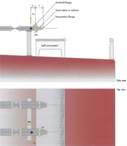
4 The distance «C» shown in Figure 2 should be as per Table 8.
| Table 8. Distance «C» | ||
|---|---|---|
| Diameter (DN) (mm) | Cmin (mm) | Cmax (mm) |
| 100 | 200 | 200 |
| 150 | 200 | 200 |
| 200 | 200 | 250 |
| 250 | 200 | 300 |
| 300/350 | 200 | 500 |
| 400 | 200 | 500 |
| 500 | 200 | 500 |
5 The maximum length (Lin Figure 2) of a spool piece or reducer should be as per Table 9.
| Table 9. Maximum length of a spool piece or reducer | |||||||
|---|---|---|---|---|---|---|---|
| Connection Diameter (mm) | 100 | 150 | 200 | 250 | 300/350 | 400 | 500 |
| Maximum Length L (mm) | 300 | 300 | 400 | 400 | 500 | 500 | 500 |