Delve into the intricate workings of Inert Gas Generators aboard LNG carriers, uncovering their fundamental role in maintaining safety and efficiency. From understanding their operational principles to mastering alarm settings, this article provides a exploration of these critical systems, essential for safe navigation and cargo management.
Reference: SIGTTO “LNG Shipping Suggested Competency Standards”, Sections:
1 Have an awareness of their purpose and operating principles
2 Know and understand their operating parameters and limitations:
- oxygen content;
- dew point;
- delivery valve operation;
- cooling requirements.
3 Know and understand their operational requirements and procedures:
- setting up;
- starting;
- shut down;
- maintenance.
4 Know and understand their alarm settings and resulting actions.
Basic info about Inert Gas Generators
The IG generator is used for:
- production of IG for atmosphere changing in tanks and lines;
- production of dry air for atmosphere changing in tanks and lines;
- production of dry air for topping up and maintaining pressure in hold spaces;
- emergency inerting of cargo hold spaces or ballast tanks by connecting spool pieces as appropriate.
What is IG used for?
IG is used for inerting and gas freeing Cargo System – Tank Constructioncargo tanks, cargo pipes, cargo hold and void spaces.
It replaces the air in the cargo systems, tanks and equipment and creates a non-flammable atmosphere that is almost devoid of O2. This prevents flammable LNG/air mixtures occurring in the tank.
It is also used for purging the tanks to remove hydrocarbons, in preparation for enclosed space entry.
Note that in the Moss tank system it can also be used for emergency cargo discharge.
IG is produced by removing O2 from the air by the process of combustion or by the utilisation of a nitrogen generator on smaller ships. In a combustion chamber, low sulphur marine gas oil is used. This is essential for the production of good quality, soot free, low O2 content IG. The quality of the IG produced will vary widely depending on the conditions under which the generator is operated.
The principle of operation of the generator is shown in Figure 2. The system is comprised of three main components:
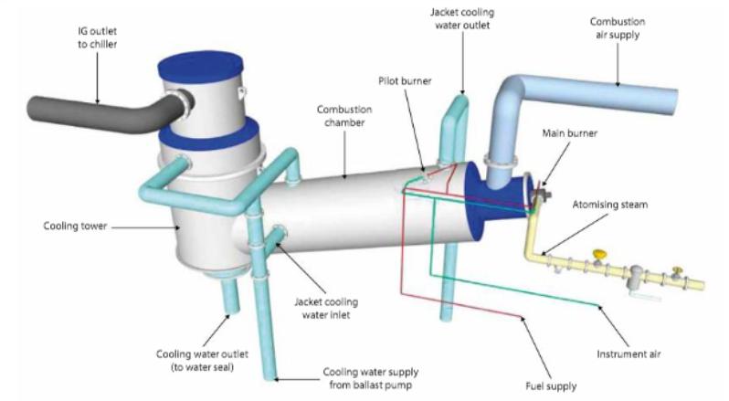
Combustion chamber with scrubber and cooler
The burner is designed to ensure proper combustion with a minimum of excess air, while the combustion chamber itself is water jacketed without a brick lining. After combustion, the gas enters the washing/cooling section (the scrubber tower) at a temperature of about +800 °C and is cooled and scrubbed by spraying with seawater. The gas leaves at approximately +5 °C seawater temperature and is essentially free of the SO2 that forms during the combustion of the sulphur that is present in the fuel.
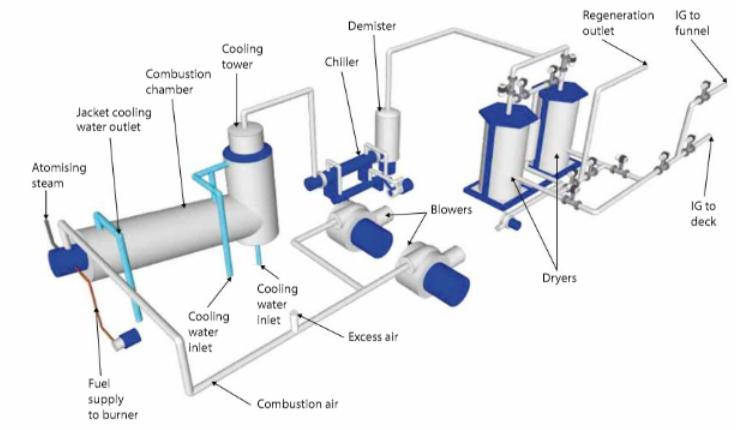
Refrigerated drier. In the refrigerated drier the IG is cooled to approximately +4 °C, which condenses most of the water vapour present in the gas.
Absorption drier. With the IG dehumidified to a dew point of about +5 °C, it will be further dried in the absorption drier (see article Air and Inert Gas Dryers“Essential Guidelines for Air and Inert Gas Dryer on LNG Carriers”).
A pressure control valve on the outlet of the absorption dryer maintains a constant pressure throughout the IG system. This ensures a stable flame in the combustion chamber.
Advantages and disadvantages of combustion type generators
Combustion type generators must be located outside the cargo area and connections to the cargo system are temporary, normally via spool pieces. When the IG plant is not in use these temporary connections must be disconnected and blanked off. To prevent gas flowing back to the IG generator during operation, two non-return valves are normally fitted on the cargo deck.
The main advantages of the combustion type generator as a source of IG are:
- the cost of the IG produced is much less than the purchase of pure N2;
- the IG plant is available when necessary.
Continuous monitoring of the O2 content on the IG supply is required, with an alarm set at a maximum of 5 % O2 by volume.
Oxygen content
An oxygen analyser will be installed to permit continuous monitoring of the O2 content while the IG plant is in use. A spare analyser and spare O2 cell should be carried. The analyser should be tested as part of the ship’s planned maintenance system (PMS).
Dew point
With the IG dehumidified to a Complete Manual for Engineers about Dew Point Reservoirsdew point of about +5 °C it will then be further dried in the absorption drier. From here it will pass through one of two desiccant dehumidifiers that use either steam or electrically heated air in the regeneration process, before passing to the delivery line. Delivery is regulated by a series of valves that monitor the values of the O2 (typically 2 %) and dew point content (typically minus 40 °C to minus 45 °C (-40 °C to -45 °C)) of the gas and, if it falls outside of these parameters, the gas will be purged to atmosphere.
Delivery valve operation. A pressure control valve on the outlet of the absorption dryer maintains a constant pressure throughout the IG system. This ensures a stable flame in the combustion chamber.
Cooling requirements
The IG is cooled by passing through a refrigerated cooler. To prevent any condensed water turning to ice, the condensed water temperature is kept close to +6 °C or less so that any recovered water drains off.
The compressor is fitted with the following alarms:
- high and low pressure trips;
- lubricating oil pressure trip;
- lubricating oil pressure differential trip to stop the compressor should the lube oil pressure drop below that of the crankcase.
The compressor is fitted with a regulator that will operate according to load demand.
There is a crankcase oil heater fitted to the compressor. This switches on automatically when the compressor stops.
Read also: Cargo Handling Systems and Specialised Equipment on LNG LPG Carriers
Start-up and shutdown procedures must always be as per the manufacturer’s recommendations for the equipment.
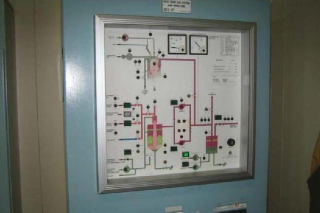
There will normally be a mimic diagram of the IG system layout on the control panel. This shows motor running lights and valve open or closed indicating lights, in addition to any activated alarms.
Setting up/starting
Setting up/starting instructions. When operating the IG generator, the following tasks have to be carried out:
- ensure all alarms and trips are operable;
- remove blanks and connect any spool piece that may be required;
- check that the control panel is on and that any alarms are cleared;
- ensure that the control air supply is available;
- start operation of the O2 analyser;
- open the suction and discharge valves on the refrigerated cooler compressor;
- open the combustion fuel oil supply valves;
- start the seawater cooling supply pump (or a ballast pump with IG mode if used) to IG plant;
- set the IG valves;
- select the appropriate IG blower;
- establish gas flow to the O2 analyser;
- after establishing that there is a cooling seawater flow, start the refrigeration cooler;
- when the suction pressure on the refrigeration plant is at 0,0 Barg, start the blowers;
- select the dry air or IG settings, as appropriate;
- if IG is selected the flame will now ignite and, as the load is increased and the unit builds up to capacity, the O2 level will reduce (the O2 content can be adjusted by manually adjusting the “load” if necessary);
- with the blowers running and the refrigerated cooler outlet temperature at +6 °C or less, start the driers;
- when the system is operating correctly, switch the unit to remote operation to put it online. Initially, the IG will be directed to the atmosphere until the required parameters are achieved(O2, CO2, dew point, soot, etc.), at which point the vent valve will close and the valve to deck (or other as appropriate) will open.
The cargo engineer would normally supervise the start-up and running of the IG generator.
Shutdown
Shutting down/stopping instructions. Procedure for stopping the IG generator:
- change the “operating mode” switch to vent the IG to the atmosphere;
- press the “stop” button on the control panel of the generator.
The fuel supply valve will automatically close and the fuel pump will stop. The seawater cooling pump will continue to run and the valve will remain open for a period of 30 minutes to allow the system to cool down. The spool piece should be removed and blanks fitted.
Maintenance
In addition to the manufacturer’s recommendations:
- when the IG plant is operating, the operator should cross check all values on the monitoring or control equipment that has local instrumentation, ensuring that any anomalies are investigated and corrected as soon as possible;
- ideally, the IG plant should be run at regular intervals with the IG production in the “purge to atmosphere” mode;
- the refrigerated cooler compressor has a dryer that must be changed regularly and a filter that must be removed and cleaned;
- all alarms and trips should be tested within each 3 month period;
- if the IG generator has been shut down, the driers should be regenerated, preferably several days before the plant is required.
IMO requirements call for continuous monitoring of O2 content on the IG supply, with an alarm set at a maximum of 5 % O2 by volume. The generator is not normally shut down on this alarm but the gas produced is vented off.
Alarms and resulting actions
The following will cause an alarm and shut down of the IG generator:
- high seawater outlet temperature;
- high seawater level in the scrubber tower;
- high seawater pressure to the scrubber tower;
- high IG temperature at the scrubber tower outlet;
- high IG pressure at the scrubber tower outlet;
- high temperature in the combustion chamber cooling jacket;
- high combustion air pressure;
- burner flame failure;
- low fuel oil pressure to the burner;
- low combustion air pressure;
- low instrumentation air pressure;
- low seawater pressure to the scrubber tower.
In addition, the following conditions will also initiate an alarm and shutdown:
- high IG temperature on the drier plant outlet, which will open the vent to atmosphere valve;
- high refrigerant temperature at the drier plant outlet, which will open the vent to atmosphere valve.