The transportation of liquefied natural gas (LNG) and liquefied petroleum gas (LPG) represents a critical aspect of global energy logistics. The unique characteristics of these commodities demand specialized carriers equipped with advanced technologies to ensure safe and efficient delivery.
- The Loaded Voyage
- Cargo temperature and pressure control
- Operation of the reliquefaction plant on refrigerated LPG carriers<
- Operation of the reliquefaction plant on LNG carriers
- LNG carriers – gas combustion unit (GCU)
- LNG boil-off gas (BOG) as fuel
- Other boil-off gas (BOG) as fuel
- Discharging
- Discharge by pressurising the vapour space
- Discharge by cargo pump
- Discharge via booster pump and cargo heater
- Tank pressure management
- Operation of the reliquefaction plant during discharge
- Completion of discharge
- Draining of tanks and pipelines
- The Ballast Voyage
- LPG carriers
- LNG carriers
- LNG Carrier – Ballast Voyage on Ships Fitted with a Combination of a Reliquefaction Plant/GCU
- Warm ballast voyage (use of GCU)
- Cold ballast voyage (use of reliquefaction plant)
- Gas-Freeing
- LPG/NH3 carriers
- LNG carriers
- Ship to Ship Transfer (STS)
In this article, we delve into the intricate features of LNG/LPG carriers, exploring their design, propulsion systems, safety measures, and environmental considerations. By understanding the complexities of these vessels, stakeholders in the energy industry can better navigate the challenges and opportunities associated with the transportation of LNG and LPG cargoes.
The Loaded Voyage
Cargo temperature and pressure control
For all fully-refrigerated and semi-refrigerated gas carriers, it is necessary to maintain strict control of cargo temperature and pressure throughout the loaded voyage. While the insulation around the tank will reduce the rate of heat leakage into the tank, it can never eliminate it. As heat leaks into the tank the liquid temperature will rise, along with the corresponding SVP in the tank. Cooling of the liquid in the tank is achieved by lowering the tank pressure, causing the liquid in the tank to boil and evaporate, which in turn causes the liquid to cool.
“Venting of the cargo to maintain cargo tank pressure and temperature shall not be acceptable except in emergency situations. The Administration may permit certain cargoes to be controlled by venting cargo vapours to the atmosphere at sea. This may also be permitted in port with the authorization of the port Administration” (IGC Code Chapter 7).
The majority of existing LNG carriers do not have a reliquefaction plant, so the BOG is burnt as a fuel in the ship’s propulsion plant. Some LNG carriers are fitted with a cargo reliquefaction plant. These reliquefaction plants may use a different principle to the systems found on LPG ships, but essentially operate in a similar way. Further description of reliquefaction plant theory and designs can be found in Chapters 2 and 4.
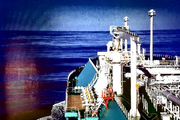
On LPG ships the pressure is controlled by running the reliquefaction plant. The BOG is condensed into liquid in the reliquefaction plant and this condensate is returned to the tank via the condensate return line, avoiding any loss of cargo. Any incondensible gases drawn into the reliquefaction plant will be vented to minimise compressor discharge temperatures and pressures.
There are occasions when the temperature of an LPG cargo on voyage must be reduced so that the ship can arrive at the discharge port with cargo temperatures matching that of the shore tanks to minimise the amount of flash gas. Depending on the cargo and reliquefaction plant capacity, on passage it can often take several days to cool the cargo by one or two degrees Centigrade. Whether this needs to be done will usually depend on the terms of the charter party.
If the condensate return is passed through the top sprays in calm weather conditions it is possible that, due to the small vapour space and poor circulation in the tank, a cold layer can form on the liquid surface. This enables the compressors to reduce the vapour pressure after only a few hours running when, in fact, the bulk of the liquid has not been cooled at all. To achieve proper cooling of the bulk liquid, the reliquefaction plant should be run on each tank separately and the condensate should be returned through a bottom connection to ensure proper circulation of the tank contents. After the cargo has been cooled, reliquefaction capacity can be reduced to o level sufficient to balance the heat flow through the tank insulation. Figure 2 shows the arrangement for cooling down cargoes on o loaded voyage.

If the reliquefaction plant is being run on more than one tank simultaneously, it is usually necessary to ensure that the condensate returns are carefully controlled to avoid the overfilling of any one tank.
Condition inspections
Gas concentrations in the interbarrier spaces of membrane containment systems may vary between loaded and ballast passages and may also be affected by the motion of the vessel in a seaway. Gas concentrations in primary barrier spaces will normally remain broadly the same for each voyage. It may be prudent to establish o formalised and efficient recording system and trend the condition of the cargo containment system. Any leaks can be identified, and appropriate intervention planned and implemented, well before any large problems occur. Main parameters such as nitrogen consumption, oxygen content, and gas content in each insulation space (primary and secondary spaces), local temperatures in the insulation spaces, loaded condition and weather conditions will commonly be monitored and recorded.

See SIGTTO “Gas Concentrations in the Insulation Spaces of Membrane LNG Carriers” (Reference 2.62) for further description and information.
Operation of the reliquefaction plant on refrigerated LPG carriers<
On a loaded voyage, and depending on cargo temperature, ambient temperature and the design of tank insulation, the plant may be operated continuously or intermittently. If it is necessary to reduce the temperature of the cargo before reaching the discharge port, to comply with the receiving terminal requirements or charter party stipulations for example, the plant will potentially operate continuously for long periods of time.
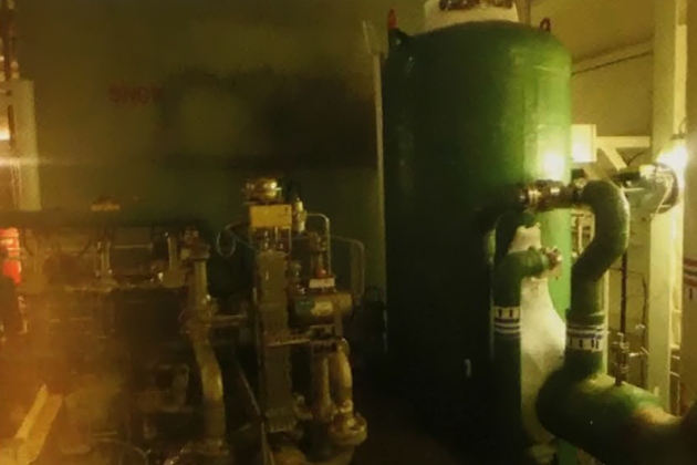
Before starting the reliquefaction plant it is necessary to ensure that, for example, oil levels in the compressors are correct and that the glycol/water cooling system is ready for operation. This will require a check to make sure the header tank is full and that the cooling fluid is circulating.
Before starting a cargo compressor, the condenser cooling system will normally be operating with seawater circulating or the refrigerant system in cascade systems running. Compressors should always be started and stopped in accordance with the manufacturer’s instructions. Compressor outlet valves will normally be opened fully and inlet valves opened slowly to minimise the risk of damage from liquid carry-over. The jacket cooling water outlet temperature should be adjusted in accordance with the manufacturer’s instructions. The following conditions, amongst others, will usually be checked regularly during operation:
- suction, inter-stage and discharge pressures;
- lubricating oil pressures;
- gas temperatures on the suction and delivery side of the compressor (note: high discharge temperature switches may only initiate an alarm and not a protective trip of the compressor). Compressor parameters should be plotted against the appropriate Mollier diagram for the cargo to show if the operation is as efficient as the design condition;
- current drawn by the electric motor;
- oil leakage from the shaft seal;
- condenser cooling water temperatures (inlet and outlet).
Stopping the compressor will normally be followed by closure of the inlet and outlet valves. The glycol/water system will usually be left running to provide crankcase heating or, alternatively, the lubricating oil heater will be switched on.
Operation of the reliquefaction plant on LNG carriers
Where fitted, the primary means of tank pressure control is through the reliquefaction plant. The gas combustion unit (GCU) is the secondary means of tank pressure control that is used, either through excess BOG mode or if there is a fault with the reliquefaction plant.
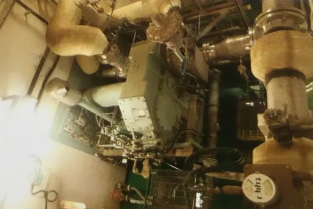
For the reliquefaction plant operation there are two modes of tank pressure control available: laden and ballast.
On loaded passage, depending on the temperature of cargo loaded, ambient temperature and the design of the tank insulation spaces, the load and operation of the reliquefaction plant can be operated at maximum efficiency. Cargo conditioning is carried out keeping in mind the requirements of the discharge terminal with respect to the cargo temperature and vapour pressure. The vapour pressure required to be maintained is entered as the set point value in the reliquefaction controller. This governs the load and flow through the reliquefaction plant to maintain the actual pressures in accordance with the set point. Excess BOG is normally disposed of via the GCU.
If a ship has previously completed a warm ballast passage it normally takes about 2 days for the insulation spaces to cool-down fully after the loading. During these first days the generation of cargo vapour is usually higher.
The following will usually need to be checked regularly:
- cargo tank liquid levels so the condensate return can be lined up;
- cargo tank pressures so that the BOG compressor flow and reliquefaction load can be adjusted to optimise the operation and fuel consumption;
- BOG, condensate and refrigeration system parameters, such as:
- suction and discharge pressures of each stage;
- LNG condensate return temperature and pressures;
- dew point;
- flow rates;
- seal gas pressures and temperatures;
- machinery lube oil levels, temperature, pressure, shaft bearing temperatures and vibration levels.
LNG carriers – gas combustion unit (GCU)
There are various methods of dealing with the BOG to minimise the release of hydrocarbons to the atmosphere. On LPG carriers there is a reliquefaction plant for each grade the ship is capable of carrying and a backup plant that can be used on either of the grades carried. On steam powered LNG carriers there are two boilers, each of which can burn the maximum BOG from the cargo. When the LNG carrier is at anchor or sailing at low speed, the excess steam not required for propulsion is dumped into a condenser.
LNG carriers with dual fuel diesel electric (DFDE) or gas burning slow speed diesel propulsion, when sailing at low speed or at anchor, have no way of increasing the load on the engines to burn excess BOG. While some vessels may have a partial (less than 100 % BOG capacity) reliquefaction plant installed, it may not be practical to have a second standby reliquefaction unit installed. In such cases, LNG carriers may be fitted with a GCU. The GCU will be capable of burning the BOG from the cargo in the event that the engines cannot consume the gas or if there is a failure of the reliquefaction plant (if fitted).
LNG boil-off gas (BOG) as fuel
The equipment and safety devices commonly used for this operation are described in article “Liquefied Petroleum Gas Reliquefaction Plant and Boil-Off ControlLNG Reliquefaction Plant and Boil-off Control Systems“.
The quantity of BOG that may be used as a fuel during the voyage will be specified by the ship’s charterers or operators. The minimum quantity to be consumed will be related to the amount of heat passing through the insulation into the tank in order that the cargo temperature and pressure may be maintained. Typical boil-off rates (BORs) for LNG carriers range from 0,10 to 0,15 % of the cargo volume per day during a loaded voyage, depending on the insulation system design. It should be noted that LNG often contains a small percentage of nitrogen, which will boil-off preferentially, reducing the calorific value of the BOG at the beginning of the loaded voyage.
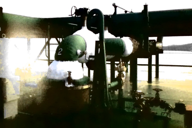
If instructed to minimise fuel oil bunker consumption during the voyage, more of the cargo can be used as a fuel. When the quantity of BOG is not sufficient, liquid cargo is pumped to the forcing vaporiser, turned into vapour and then combined with the natural BOG to make up the additional fuel demand.
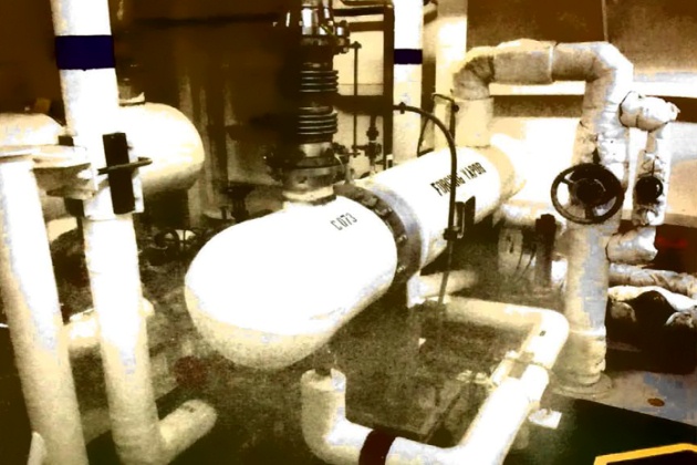
The compressors used on LNG ships usually have shaft seals that are pressurised with nitrogen. An adequate nitrogen supply will therefore need to be available at all times when the compressor is running and, as with LPG compressors, care should usually be taken to avoid liquid being carried into the compressor via the vapour suction line.
Other boil-off gas (BOG) as fuel
The IGC Code currently only addresses the use of LNG BOG as fuel, although it allows for other gas cargoes to be used subject to Flag Administration approval of designs meeting the same level of safety as for LNG (methane). The systems for these other gas cargo fuels, such as ethane, will be similar to LNG BOG fuel systems, comprising of fuel pumps, compressors and vaporisers.
Discharging
When a ship arrives at the discharge terminal, cargo tank pressures and temperatures will usually be in accordance with terminal requirements. This will help maximum discharge rates to be achieved.
As with the loading operation, there will normally be a pre-transfer meeting between the ship and the terminal to review and agree a discharge plan.
The method of discharging the ship will depend on the type of ship, cargo specification and terminal storage. Three basic methods may be used:
- Discharge by pressurising the vapour space;
- discharge by cargo pump, with or without booster pumps;
- discharge via booster pump and cargo heater.
Before transfer of refrigerated cargoes, the pipelines and shore arms will be cooled prior to starting the discharge operation. This is normally achieved by using the ship’s spray pumps and, depending on the terminal requirements, the ship’s lines may be cooled down prior to arrival alongside.
Discharge by pressurising the vapour space
A pressurised discharge, using either a shore vapour supply or a vaporiser and compressor onboard, is only possible where Type C tanks are fitted. Using this system, the pressure above the liquid cargo is increased, forcing the liquid to a booster pump, which then transfers the cargo to the terminal.
Discharge by cargo pump
As the discharge proceeds the liquid level in the cargo tanks will be monitored. Discharge and ballasting operations should be carefully controlled, bearing in mind, for example, ship stability and hull stresses.
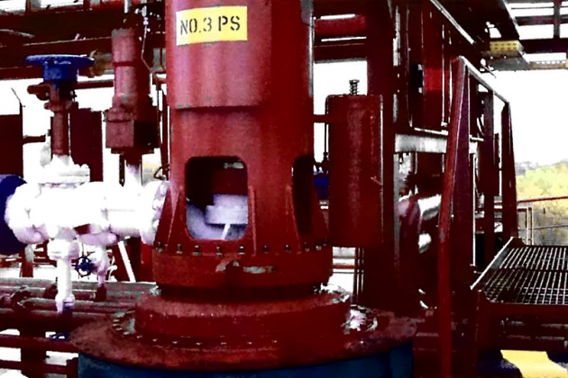
Removal of liquid from the cargo tank may cause changes in interbarrier or annular space pressures and these will usually be monitored throughout the discharge.
Discharging by centrifugal cargo pumps, either alone or in series with booster pumps, is the method adopted by most ships and an understanding of the centrifugal pump characteristic (as outlined in article “Cargo equipment for gas carriers carrying LNG/LPGCargo Pumps“) is essential for efficient cargo discharge. Figure 11 shows a cargo pump Q/H curve (flow against head) superimposed on a system friction (ie flow resistance) curve. The graph shows the head or back pressure in mlc (metres liquid column) in the terminal pipeline system against flow rate measured in cubic metres per hour. Increasing the flow rate increases the back pressure. This varies approximately as the square of the flow rate, giving the characteristic shape of the system friction curve shown. The intersection of the two curves is the flow rate and head at which the pump will operate.
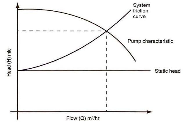
Some of these points are further demonstrated by inspection of Figure 12.
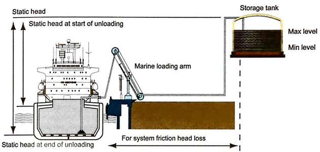
For a ship unloading, assuming constant pressures in the ship’s tanks and the land storage tank:
- the static discharge head will not vary significantly;
- the static suction head will decrease as cargo is discharged (more head required so flow will decrease);
- the friction head will increase with capacity increase.
This diagram shows a gas carrier alongside a jetty discharging to shore storage set at some elevation. The elevation of the tank introduces the concept of static head, which is the back pressure exerted at the pump even when pumps are not running. It can be seen that the static head changes as the ship moves up and down with the tide and as the level in the shore tank alters. The diagram also indicates that the friction head loss largely depends on the length of the pipeline system.
Running pumps in parallel
It is normal for pumps to run in parallel during a gas carrier discharge. Figure 13 shows the pump characteristics using one, two, three or four similar pumps in parallel. (This family of curves is derived from the principles discussed in article “Cargo equipment for gas carriers carrying LNG/LPGCargo Pumps“).
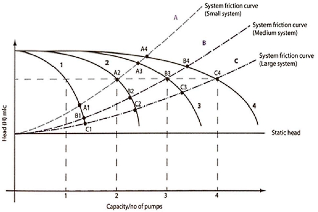
System characteristic “A” indicates a small diameter shore pipeline, “B” a larger diameter pipeline and “C” a very large diameter pipeline with shore tanks situated nearby. “C” provides the least resistance to cargo flow.
If a ship with pumping characteristics shown in Figure 13 is discharging to a terminal presenting only minor restrictions to flow, equivalent to “C“, the operating point of the ship/shore system moves from points C1 through to C4 as the number of cargo pumps in operation is increased from one to four. Under such conditions, the total flow achieved (when using four pumps) is only marginally less than the total theoretical flow (assuming no resistance). With such a shore pipeline system it is, therefore, probable that all four pumps (and maybe more) can be run to good effect.
Where flow restrictions are high, equivalent to “A“, it can be seen how little extra flow is achieved by running more than two pumps. By running three pumps the operating point moves from A2 to A3, achieving some extra throughput. By running four pumps the operating point moves from A3 to M, achieving a very small increased flow. In such cases, much of the energy created in the additional pumps is imported to the cargo. This is converted to heat in the liquid and results in an increase in cargo temperature. This increases flash-gas boil-off as the liquid discharges into shore storage, and this excess will be handled by the shore compressors. If the shore compressors are unable to handle the additional flash-gas, the terminal will require a reduction in flow rate to avoid lifting the shore relief valves.
If the shore line has a very restricted capacity, the net effect of running an unnecessary number of pumps can be to decrease the overall discharge rate rather than to increase it.
It will be interesting: Gas laws, thermodynamic principles and reliquefaction
The actual system characteristic applicable at any terminal will usually be known to shore personnel and they will usually have such curves available. In using the graphs, personnel should note that the system characteristic can vary with the size of the chosen pipeline and with variation in the pipe lengths from the jetty when alternative shore tanks are used. If a range of pipelines and tanks are available at any one terminal, it may be appropriate for terminal personnel to have a number of system characteristics already pre-calculated and available for use during pre-transfer discussions.
In any case, during the pre-transfer discussions, such matters will normally be covered and the optimum transfer rote agreed.
Observing pressure gauges at the manifold will usually give a good indication if it is worthwhile running, say, four pumps or six pumps. The discharge rate should not, ordinarily, be reduced by throttling valves at the ship’s cargo manifold if the shore cannot accept the discharge rate. Throttling in this manner further heats up the cargo. However, gas carriers with only limited recirculation control may have to use manifold valves to throttle pumps.
When operating booster pumps in series with primary pumps, the primary pump discharge will not usually be throttled as this is likely to cause cavitation in the booster pump which in turn will damage it. The outlet pressure from the primary plus booster pump combination can be regulated by throttling at the booster discharge or possibly by recirculation from there back to the cargo tank.
Discharge via booster pump and cargo heater
Where cargo is discharged from a refrigerated ship into pressurised storage, it is necessary to warm the cargo (usually to at least 0 °C). This means running the cargo booster pump and cargo heater in series with the cargo pump. Prior to operation of the booster pump and heater, leak tests will usually be conducted on the heater and correct operation of relevant safety shutdowns demonstrated.
Thereafter, once seawater flow is established through the heater, the booster pump and heater may be slowly cooled down by very slow throughput of liquid from the cargo pump discharge. Once cooled down, the discharge valve can be opened until the desired outlet temperature is reached. The discharge will normally be accomplished at a reduced rate compared to fully-refrigerated discharge rates. It is normally considered important to ensure that the cargo pumps maintain adequate flow to the booster pump at all times. Figure 14 shows a typical layout.
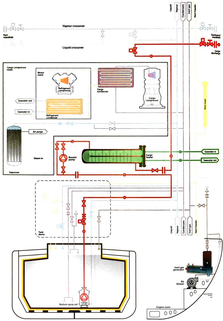
Heating cargo during discharge always entails a risk of freezing the circulating water in the heater. In addition to checking the cargo outlet temperature and the booster pump suction during operation, attention should usually also be paid to the seawater inlet and outlet temperatures and pressures. The seawater outlet temperature should not normally be allowed to fall below the manufacturer’s recommended limit. A low temperature switch will stop cargo flow through the heater in the event of low seawater discharge temperature. The pre-operation checks will normally demonstrate that this low-temperature shutdown works correctly.
Tank pressure management
When liquid is pumped from a ship’s tanks, pressures tend to fall. Boil-off due to heat flow through the tank insulation takes place continuously and this generates vapour within the tank. The boil-off is usually insufficient to maintain cargo tank pressures at acceptable levels, but this ultimately depends on the discharge rate, cargo temperature, ambient temperature and insulation efficiency. Where vapours produced internally are insufficient to replace the liquid volume removed it is usually necessary to add vapour to the tank if discharge is to continue at a constant rate. This vapour may be provided either by using the ship’s cargo vaporiser (Figure 15), or from the terminal (via a vapour return line) (Figure 16).

(Vapour returned to the cargo tank during discharge from the cargo vaporiser)
When using the cargo vaporiser, the liquid can be supplied by being bled from the main liquid line or pumped directly from a tank.
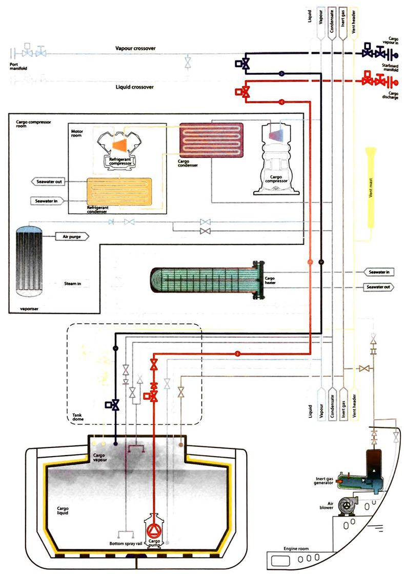
(Vapour returned to the cargo tank during discharge from the shore via the ship’s vapour return line)
Operation of the reliquefaction plant during discharge
The operation of the reliquefaction plant during cargo discharge is Fairly independent of whether the gas carrier has been instructed to keep the cargo tanks in a cold or warm condition on the ensuing ballast voyage. Most terminals would expect the reliquefaction plant to be stopped or offline while opening quantity calculations are carried out and ESD tests are completed.
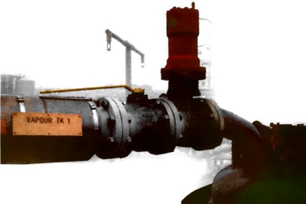
Completion of discharge
During discharge, the pressure of the liquid at the suction inlet of the pump needs to exceed the SVP by an amount known as the minimum net positive suction head (NPSH) to help to avoid cavitation of the centrifugal pump. The required minimum NPSH, expressed as an equivalent head of liquid above the pump suction, may vary from one metre (at maximum pump capacity) to 200 mm (at reduced flow). If the vapour space pressure can be increased above the SVP by the supply of extra vapour from the shipboard vaporiser, cavitation can be delayed as the liquid level approaches the bottom of the tank.
This increase in vapour space pressure is common practice on fully-pressurised and semi-pressurised ships and may also be carefully applied to fully-refrigerated cargoes, particularly where maximum cargo out-turn is required in preparation for gas-freeing. Whether this extra vapour pressurisation is used or not, there will be a liquid level at which the flow through the pump becomes erratic. Gradual reduction of the flow rate at this point, by careful throttling of the discharge valve, reduces the NPSH requirement and allows continued discharge to a lower level. It should be remembered, however, that a pump discharge valve will not usually be used for flow control if the pump is operating with a booster pump as the booster pump may cavitate and damage may be the result (see point “Discharge by cargo pump”) above.
Draining of tanks and pipelines
Manifold draining (general)
On completion of discharge, liquid cargo will be drained from all deck lines and cargo hoses or MLAs. The principal objective is to disconnect the MLAs in a manner that eliminates any risk of liquid release and reduces the release of cargo vapour to the atmosphere to an absolute minimum. To help this operation to be conducted safely and in a timely manner, a procedure will usually be put in place and good communication between the ship’s staff and the shore operational staff will need lo be maintained.
The process has a number of logical steps:
- Lining up the drain system from the manifolds to a tank.
- Isolation of liquid and vapour valves on either side of the manifold connection.
- Removal of liquid from the manifold connection and MLAs.
- Purging of toxic and/or flammable vapours from the connection.
- Verification that the target conditions (gas concentrations) have been achieved.
- Disconnection of the manifold.
Opening a manifold drain to atmosphere to check that liquid has been removed is polenlialy dangerous.
While time or number of cycles of pressurisation/depressurisation may be a useful indicator, the principle of testing with a detector will normally be adhered to. If reliance is placed only on a time or cycle based system, a leaking valve in the cargo system, on ship or shore, may go undetected, leading to disconnection taking place in unsafe conditions.
If there is a considerable delay between testing and disconnection, an MLA is normally retested in case vapour has built up (due to leaking ESD valves or liquefied gas being trapped outside the ESD valve).
After disconnection, it is prudent to inspect any filter (where applicable) in the manifold piping followed by the immediate installation of the manifold blanks. The drain and vent valves can normally then be dosed and the blank flange installed on the MLA.
Manifold draining (LPG carriers)
On LPG carriers, after discharge the cargo compressors are switched to “hot gas” and set-up to return to the manifold and blow hot gas to the manifold land ashore), clearing the manifold of any residual cargo liquid. Alternatively, the shore may either blow the MLA with hot gas or nitrogen, with any residual liquid draining to the cargo tanks. This second option, using nitrogen, is normally avoided on LPG carriers as nitrogen is an incondensible gas and will cause running issues with the reliquefaction plant. In such cases where this option is employed, the vessel would have to monitor the cargo compressors and the purge gas condenser (see article “Liquefied Petroleum Gas Reliquefaction Plant and Boil-Off ControlPurge gas condenser“) and clear them of incondensibles. Only after depressurising all deck lines and purging with nitrogen will the ship/shore connection be disconnected.
Manifold draining (LNG carriers)
The “LNG Transfer Arms and Manifold Draining, Purging and Disconnection Procedure” (Reference 2.63), may be used as the standard procedure for draining and purging of both liquid and vapour MLAs. Ship’s crew may wish to compare it to the terminal procedure during the pre-transfer meeting. Any divergence has to be agreed between the ship and the shore and the revised procedure signed by both parties and issued for use on completion of bulk cargo transfer.
Once the verification process is complete and the arm fully depressurised, the drain valve will usually be left open to prevent over-pressurisation in the case of any leakage past valve seats. A final check will be made to ensure that the methane content remains below 2 % by volume before disconnection. Disconnection will not normally commence until all MLAs have been satisfactorily purged in case the incorrect MLA is inadvertently selected and disconnected.
The Ballast Voyage
LPG carriers
In the refrigerated LPG trades, it is common practice to retain a small quantity of cargo on board after discharge, which is known as “heel“. The heel is used to maintain the tanks at a reduced temperature during the ballast voyage, but this only applies when the same grade of cargo is to be loaded at the next load port.
In general, the quantity retained on board as heel depends on:
- commercial agreements;
- the type of gas carrier;
- the next loading terminal’s requirements;
- the next cargo grade.
With LPG cargoes, the small amount of liquid remaining after discharge will usually be sufficient to provide the necessary cooling effect during the ballast voyage. Cooling is carried out by intermittent use of the reliquefaction plant, returning the condensate to the tanks to ensure arrival at the load port with tanks and product suitably cooled.
If the ship is proceeding to a loading terminal to load an incompatible product, none of the previous cargo will usually be retained onboard. If small amounts remain this may be recovered to the deck tanks, if fitted, to ovoid contamination of the next cargo.
LNG carriers
On LNG carriers, the quantity of heel retained will be provided by Charterer’s instructions and will generally depend on a number of factors:
- whether the ship is to arrive cold or warm at the next load port;
- how much natural gas is to be used in lieu of bunker fuel during the voyage;
- the length of the voyage;
- the voyage speed;
- anticipated waiting time at the next load port before berthing.
Optimising the quantity of heel for the ballast voyage is important. If too much is retained and the LNG carrier arrives at the load port with excessive heel, then cargo to be loaded is shut out. If too little heel is retained the LNG carrier may not arrive cold enough and may need further cooling time before loading operations commence, extending the time in port. Too little heel may also result in the need to burn conventional fuel.
LNG Carrier – Ballast Voyage on Ships Fitted with a Combination of a Reliquefaction Plant/GCU
Warm ballast voyage (use of GCU)
On completion of cargo discharge, stripping of the cargo tanks will not completely remove all cargo liquid and will result in a quantity of cargo that is unpumpable remaining on board.
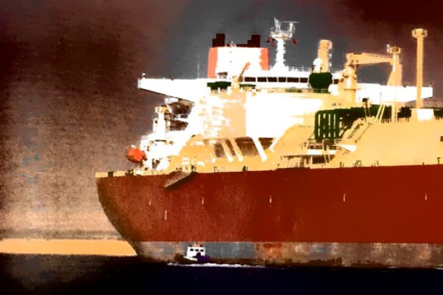
In this condition it is not possible to run the reliquefaction plant to manage tank pressures. The BOG from the tanks will be compressed in the BOG compressor and then pass through the BOG heater before it is supplied to the GCU. The GCU may be only required intermittently, to maintain tank pressure, as the cargo tanks warm up to ambient temperature.
Cold ballast voyage (use of reliquefaction plant)
The main advantages of a cold ballast voyage are:
- reduced discharge time (as no stripping is required at the discharge port);
- no cool-down is required at the load port;
- no burning of cargo in the GCU to manage tank pressures.
When the spray pumps are in use to maintain or cool-down the tanks in preparation for loading, vapour generation in the cargo tanks increases and the reliquefaction plant may be utilised to cope with this. Normal practice is to cool the tanks down just before arriving at the load port, ready to load per cargo tank design.
By doing this the LNG carrier is able to commence loading operations immediately after the shore MLA cool-down is completed.
Gas-Freeing
Preparation for a change of cargo or entry into a tank is a time consuming operation. Gas-freeing of cargo tanks can be a frequent operation on on LPG carrier. If the next cargo is not compatible with the previous, it is often necessary for the tanks to be gas-freed to allow a visual inspection. This is commonly the case when loading chemical gases such as VCM, ethylene or butadiene. LNG carriers will typically only be gas-freed in preparation for drydock or if there is a requirement to enter a tank for maintenance between drydocks.
LPG/NH3 carriers
When a ship receives voyage orders it is prudent to make a careful check on the compatibility of the next cargo. (It is also prudent to check compatibilities and the ship’s natural ability to segregate if more than one cargo grade is to be carried. On such occasions, special attention will be given to the ship’s reliquefaction plant as there must be a reliquefaction plant for each grade the ship is capable of carrying and a backup plant that can be used on either of the grades carried). There may also be a need, when changing cargoes, to replace the lubricating oil in compressors for certain cargoes. This is discussed in article “Liquefied Petroleum Gas Reliquefaction Plant and Boil-Off ControlLPG Reliquefaction Plant and Boil-Off Control“.
The tables in article “Properties of liquefied gasesChemical Reactivity and Compatibility” provide guidance on the compatibility of gases. The tables also cover cargo compatibility with respect to the construction materials commonly used in cargo handling systems. For further information on cargo reactivity, the appropriate safety data sheets (SDS) for the cargo should be consulted.
To obtain a gas-free condition the full process is:
- remove residual liquid from the tank;
- worm the tank with hot cargo vapours (if necessary);
- inert the tank;
- ventilate the tank with air;
- test the cargo tank atmosphere.
However, depending on the particular change of grade, it may not be necessary to include all of these steps.
These procedures are required prior to tank entry for inspection or when gas-freeing the ship for drydock.
Removal of residual liquid
Rarely can all of the liquid be removed by normal cargo stripping operations. Depending on cargo tank design, residual liquid can be removed by pressurisation or hot gas vaporisation.
LPG carriers may be fitted with deck tanks that can be used to store liquid recovered from the cargo tanks. The contents of the deck tanks may be retained and used, at some future time, to provide vapour for gassing-up purposes when changing grades on passage. It is important to keep good records of deck tank contents.
Liquid stripping for Type C tanks
A cargo stripping line is usually provided for ships with Type C cargo tanks.
By pressurising the cargo tanks on these ships (for example, by using the cargo compressor or shore-supplied nitrogen) residual liquid can be lifted from the tank sump into the stripping line and then to deck level. It may be stored temporarily in a cargo tank selected for returning to the shore or, where fitted, it may be stored in a deck tank provided for that purpose. Draining should continue until all liquid cargo is removed from the cargo tanks, as verified by the bottom sampling line. The pressure necessary to remove residual liquid will depend on the specific gravity of the cargo and the depth of the tank (see Figure 19).

Liquid freeing for other tank types
The removal of all cargo liquid residues on the large Type A and Type B prismatic tanks is not generally possible by pressurisation. Instead, cargo liquid residues will be vaporised, which is normally achieved using puddle heating coils.
When puddle heating coils are used the heat source in the coils is the hot gas discharged from the cargo compressor. Cool vapour is drown from the cargo tank atmosphere and passed through the compressor, where the heat of compression causes increased vapour temperatures. This hot gas can be led directly to the heating coil system, by-passing the condenser, where heat is transferred to the liquid cargo residue. In this way the remaining liquid is evaporated and a result of the heat transfer is to condense the hot gas in the coils into liquid that is normally returned to a deck tank.
An alternative to the use of puddle heating coils is to supply hot gas (from the compressor) directly to the tank bottom. However, this results in much slower evaporation of remaining liquids than the method described previously as the hot gas only flows over the surface of the liquid pool rather than causing boiling within it.
Read also: Equipment and cargo system of LNG onshore terminals
When a ship is at sea, to finalise either type of operation, cargo tank vapour is normally vented to atmosphere via the vent riser. Alternatively, it may be condensed and transferred into deck storage. If the ship is in port, where venting to atmosphere is seldom allowed, the condensate would either be transferred to the shore or returned to a deck storage tank.
When all tanks have been satisfactorily liquid freed, pipework and other in-line equipment will be blown free and drained of liquid through the appropriate drain valves.
Warming up
When cargo tanks have to be fully ventilated with fresh air, depending on tank temperatures and design considerations, it may be necessary to warm-up the tanks prior to inerting. This is achieved by controlled circulation of warm cargo vapours through the tanks and is carried out before inerting takes place.
In the same manner as cool-down, the rate of warm-up will be carefully controlled in accordance with the ship’s operating manual, although this is usually less of a problem as warming up usually takes longer than cooling down.
Consideration will also be given to the dew point of the air that will be introduced into the tank. Ideally, the tank will be warmed to a temperature above the dew point of the vapour that is next to be introduced into the tank. Failure to do this will result in water vapour condensation.
Inerting – to remove cargo vapour before gas-freeing
Inerting is always necessary after flammable cargoes when tanks must be opened for internal inspection. Removal of cargo vapour with inert gas is carried out to reduce gas concentrations to a level where aeration can take place without the tank atmosphere passing through the flammable envelope (see article “Properties of liquefied gasesSuppression of Flammability“). This safe level will correspond to a point below the critical dilution line (see Figure “Properties of liquefied gasesFlammable range diagram“) as found on a graph for the product in question. When inerting in this manner, the hydrocarbon content in the inert atmosphere is reduced to about 2 % before air blowing is commenced.
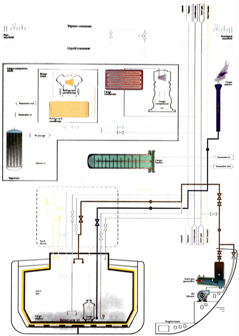
The method of changing the tank atmosphere will be either dilution or displacement, as described in point “Changing Tank Atmospheres” above. This operation is normally carried out while the gas carrier is at sea, venting cargo vapour to atmosphere, if necessary.
When the cargo tanks have been inerted, the pipelines and cargo machinery will also be inerted to reduce the gas concentration to less than 2 % by volume.
Aerating
Once the cargo system has been purged with inert gas the tanks can be ventilated with air. The air is normally supplied using the air blowers providing dry air from the inert gas plant. If the tank is being prepared for inspection prior to a cargo grade change, ventilation with air will normally only take place once the ship’s tanks are warmed to a temperature above the dew point of the air to be introduced. Failure to take this precaution could result in problems when preparing the tank for new cargoes. If condensation is allowed to form, its removal can be a lengthy and costly operation, although this may not be so critical if the gas carrier is going to drydock, where ventilation with fresh air may be sufficient. Figure 21 shows a pipeline set up for aerating tanks.
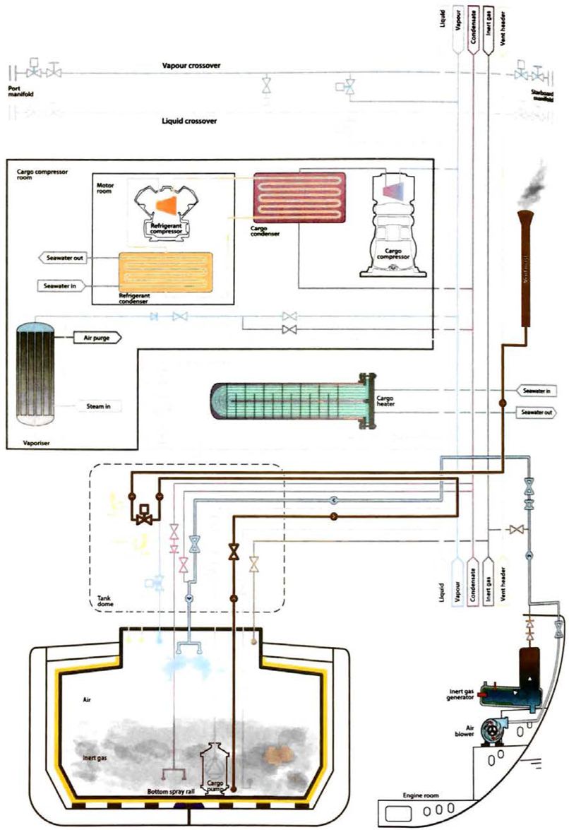
To ensure uniformity in the tank atmosphere, various levels and positions within the tank will be monitored prior to tank entry.
When aerating the cargo tanks to remove inert gas, air is introduced at the top of the cargo tank or the bottom depending on the method used. Using the displacement method air, being lighter than combustion-type inert gas, is introduced at the top of the tank. If aerating by dilution method, the air can be introduced either in the top or bottom of the tank.
Some ships may be fitted with high-capacity fans on deck to ventilate the cargo tanks. These can be connected, via hose, to blow air at different levels in the tanks to ensure effective ventilation. Some fully-refrigerated LPG carriers may be fitted with deck mounted gas freeing fans, where the air is led from the gas freeing fan to the tank via large diameter concertina-type hoses. These hoses allow the air to be introduced at different levels within the tank to ensure the effective introduction of fresh air to all areas of the tank.
Ammonia – special procedures
Certain cargoes present particular difficulties when trying to remove all traces of the product, and ammonia is one such cargo. When a ship is switching from ammonia to LPG, virtually all traces of vapour will be removed from the system. The major quality concern for ammonia in LPG is corrosion of the copper/zinc alloys used by downstream LPG customers. Prior to loading the next cargo, an allowable concentration of ammonia vapour in a tank atmosphere is usually quoted as less than 25 ppm by volume. This results in a time consuming operation.
The first stage when switching from ammonia is to remove all liquid ammonia from the system. It is prudent to observe tank temperature readings carefully to confirm that all liquid has been removed. However, isolated pools of ammonia liquid may sub-cool and remain when the rest of the tank is warming up. Any liquid remaining will evaporate eventually and frustrate progress with gas-freeing.
Once cargo tank temperatures have been warmed to substantially above the dew point of the air, the ammonia vapours are usually dispersed by blowing warm fresh air through the system. (Combustion-type inert gas cannot be used due to the formation of ammonia carbamates when ammonia is in contact with carbon dioxide, see article “Properties of liquefied gasesThe chemical compatibility of cargoes with inert gas or nitrogen“). The continued use of warm dry air should prevent water vapour condensation, limiting the seepage of ammonia into porous tank surfaces. Ventilation of tanks and the cargo system at the highest practical temperature is advantageous as this encourages the release of ammonia from rusty surfaces. (Ammonia is released significantly faster when the temperature rises above 0 °C).
- this procedure should normally only be conducted by ship’s staff who have experience of this technique;
- the benefit of water washing is limited to certain types of tank. (This technique is not always practical for large fully-refrigerated ships with prismatic tanks, and there is a risk of vacuum damage if the process is carried out incorrectly);
- when switching from ammonia to LPG, water can hold ammonia in solution and this can be a contaminant for future cargoes. Therefore, water washing will commonly only be used for cargo tanks that are completely clean, rust-free and have a minimum internal structure, allowing for full and effective drainage;
- all traces of water will usually need to be removed at the end of washing to stop the formation of ice or hydrates;
- the high solubility of ammonia in water (900:1 with water at 0 °C and 500:1 with water at 20 °C) can lead to dangerous vacuum conditions being created within a tank. It is, therefore, common practice to ensure adequate air entry into the cargo tank during the water washing process.
After water washing all water residues are removed using either fixed or portable pumps. Subsequently, tanks and pipelines will be thoroughly dried before further preparations for cargo loading are made. To maintain maximum dryness, ventilation of the tanks will continue using air with a dew point lower than the tank atmosphere temperature.
Proper precautions need to be taken when gas freeing, water washing, aerating, or drying tanks that contained ammonia as last cargo, such as the wearing of appropriate PPE and monitoring of environmental conditions fie wind direction).
LNG carriers
Experience has shown that, in normal service, it is not usually necessary to gas-free LNG cargo tanks for routine inspections between drydockings. Only if a problem occurs within a tank, which requires access into that tank, would a single tank be gas-freed between drydocks. The basic steps are the same as for an LPG carrier, but the equipment and procedures used may be different.
Removal of residual liquid
With the exception of Moss spherical or Type C tanks, which can be pressure stripped in the event of a complete pump failure, the removal of cargo liquid residues on other tank types is not generally posssible by pressurisation.
Unlike some LPG ships, LNG ships are not fitted with puddle heating coils in the bottom of the tank and the only way in which the residual liquid in the tank can be removed is by blowing warm vapour over the liquid to evaporate it.
Vapour is drawn from the top of the tank via the vapour line, passed through a high duty compressor and heater and returned to the bottom of the tank via the liquid line. Some temporary piping connections may be used, and/or spectacle flanges may be turned, in order to line up the piping correctly for this operation. As the liquid evaporates the pressure in the tank will rise. The increasing vapour pressure in the tank is managed either by burning the gas in the engine room, burning the gas in the GCU, venting to atmosphere or a combination of these, depending on the equipment on the LNG carrier. Whichever method is chosen the rate of pressure increase in the tank can be controlled by a combination of the outlet temperature from the heater and the capacity control of the high duty compressor.
The temperature sensors may not give an indication of when the liquid has evaporated, particularly in membrane tanks, due to the large flat surface area in the bottom of the tank and the rolling of the LNG carrier while at sea. Overall, the tank pressure profile will provide an indication of when all the liquid has been evaporated.
Warming Up
The tanks will be warmed up prior to inerting for the following reasons:
- so that the tank will be warmer than minus 78 °C (-78 °C) to prevent the CO2 in the inert gas from sublimating (ie CO2 goes directly from a vapour to a solid at minus 78 °C (-78 °C) at atmospheric pressure;
- so that the tank will be warmer than the dew point of the inert gas;
- so that the tank will be warmer than the dew point of the air that will be introduced into the tank to prevent condensation forming from the water vapour in the air.
The method of tank warming is the same as that used for the removal of residual liquid in the tank. Vapour is drawn from the top of the tank through the vapour line to the high duty compressor, through the heater and returned to the bottom of the tank via the loading line. In this operation, as there is no longer any liquid turning into vapour, the pressure rise is much more gradual, so the outlet temperature from the heater and capacity of the high duty compressor may be increased to speed up the operation.
Care will be taken to ensure that the tank itself is warmer than the dew point of the air, not just the atmosphere in the tank. For membrane tanks it is common practice to warm the tank until the temperature at the secondary barrier has reached the desired value.
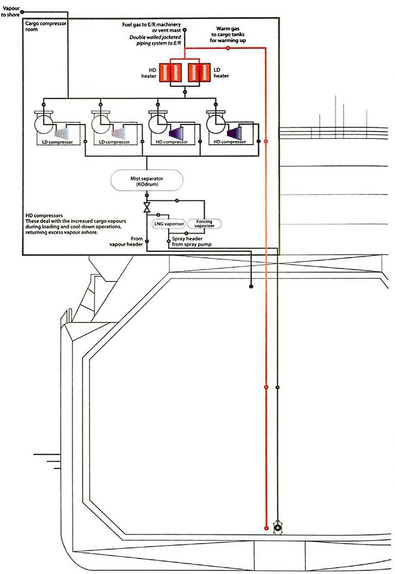
Inerting before gas-freeing
The displacement method of atmosphere changing is used on LNG carriers and, since inert gas is heavier than warm methane vapour, the inert gas is introduced into the tank at the bottom, via the loading line, while methane vapour is exhausted from the top of the tank via the vapour line.
The methane vapour that is exhausted from the tank can be either burnt in the engine room as fuel, burnt in the GCU, vented to atmosphere, if allowed by local regulation, or a combination of these options depending on the equipment fitted onboard.
When the cargo tanks have been inerted the pipelines and cargo machinery must also be inerted to reduce the gas concentration to less than 2 % by volume.
Aerating
Once the cargo system has been purged with inert gas it can be ventilated with air. LNG carriers are particularly sensitive to water in the cargo system and it is common practice that, even during drydock, the tanks are ventilated with dry air. For this reason it is normal to aerate the tanks with dry air supplied from the inert gas generator.
By this time the tank will already have been warmed up to a temperature greater than the dew point of the dry air to prevent condensation in the tank.
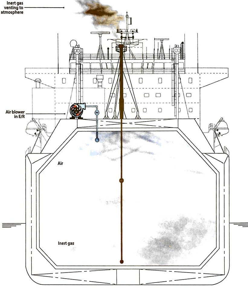
The dry air is lighter than the inert gas and is, therefore, introduced from the top of the tank via the vapour line while the inert gas is exhausted from the bottom of the tank via the liquid line and vented to atmosphere via the forward vent mast.
Once the tanks are aerated the cargo pipelines and machinery will be aerated.
Ship to Ship Transfer (STS)
The transfer of both LPG and LNG cargoes from one ship to another, via flexible hoses, has become a common practice in many areas. In some cases, LNG is transferred via MLAs between LNG carriers and floating storage and regasification units (FSRUs) or floating LNG vessels.
In all cases, detailed recommendations for the safe conduct of such operations are given in the “Ship to Ship Transfer Guide for Petroleum, Chemicals and Liquefied Gases” (Reference 2.14). Before any such operations are arranged, it may be prudent to consult this publication, as compliance with it may be required under any charter party under which the ship is operating.
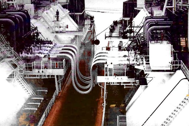
Ship compatibility is a key consideration within the STS Transfer Guide. For liquefied gas STS transfer, ship compatibility will include, in addition to general ship details, the manifold dimensions, mooring data and ESD system configuration/compatibility. Several other issues need to be considered prior to STS transfer operations, which include, but are not limited to:
- vapour pressure control;
- testing of ESD on both vessels;
- cool-down process (each ship cooling down their own lines prior to one vessel, generally the delivering vessel, cooling down the transfer hoses);
- custody transfer procedure;
- draining and purging of lines and hoses on completion.
Controlling the cargo vapour pressure is considered the limiting factor in determining the overall length of the cargo transfer operation. The delivering vessel will need to condition the cargo prior to STS operations to ensure it is as cold as possible, as it will warm up during the transfer process.
The receiving vessel may also be asked to condition its tanks to be colder than would normally be required at a loading terminal, to reduce the amount of BOG generated during the STS transfer. Once the transfer has commenced, tank pressures can be controlled by burning the BOG in the vessels’ boilers (utilising steam dump as needed) or generators and GCUs on LNG carriers, and by the reliquefaction plant on LPG carriers.
