LNG Industry Insights reveal significant trends that are shaping the future of the liquefied natural gas sector. As demand for cleaner energy sources rises, integrated marine services are becoming essential for LNG, FLNG, and FSRU terminals. European shipyards are at the forefront, developing innovative technologies that enhance efficiency and safety in the LNG supply chain. Established containment systems have proven their reliability, continuing to meet the industry’s rigorous standards.
Furthermore, key players in the market are leveraging new advancements to stay competitive. Overall, these insights highlight the dynamic and evolving nature of the LNG landscape, essential for stakeholders aiming to navigate its complexities.
Cavalcade of LNG non-starters
Few in number, today’s successful LNGC containment systems emerged from a myriad of competing ideas that did not make it to the high seas.
No new LNG carrier cargo containment system has been introduced since 1987. The ships in today’s fleet sport one of only five tried and tested types. They are IMO Type C pressure vessels, Moss spheres, IHI SPB tanks and the two Gaztransport & Technigaz (GTT) membrane tank systems.
The three principal tank systems for conventional size LNGCs – the Moss spheres, the Gaz Transport membrane and the Technigaz membrane – have been established since the early years of the industry. Delivered in August 1969, the 71 500 m3 Polar Alaska was the first vessel to be fitted with the Gaz Transport membrane system while the inaugural Technigaz stainless steel membrane ship was the 50 000 m3 Descartes, completed in September 1971. The 88 000 m3 Norman Lady, which entered into service in November 1973, was the first LNGC with Moss spherical tanks.
That is not to say that the industry has been short of ideas. Over the 50 years since LNG was first carried by sea many containment system designs have been put forward as a means of transporting this challenging cargo.
However, as the designers of these concepts will be quick to point out, the path to commercial acceptance is a difficult one.
A number of obstacles have to be overcome before a new containment system can be considered as being viable for an LNGC newbuilding project. Designers will encounter considerable development costs, including those associated with a rigorous prototype testing programme. Approvals from class societies and regulatory authorities will then be required and any new system overcoming all these hurdles still has to convince the traditionally conservative shipowner of its merits.
The following paragraphs describe some of the LNGC containment systems that have been unveiled over the years but, for one reason or another, were never chosen to grace an Rules and Regulations for LNGCLNGC newbuilding in commercial service. The vast majority were introduced during the industry’s formative years.
To meet the needs of a 1952 proposal to ship Louisiana gas to Chicago, consulting engineer Willard S Morrison designed a Mississippi River barge with five 15 m diameter, vertically mounted, mild steel, cylindrical tanks lined with balsa wood insulation up to 30 cm thick. On the drawing board each tank was provided with a 1,5 m diameter central column in which regasification equipment was installed to enable the discharge of regasified cargo in Chicago. This project, and the others highlighted below, never materialised.
Dytam’s concept of a vessel with a concrete hull
In 1954 the possibility of shipping LNG from Venezuela to the UK was investigated. Six ship designs were produced, all of which had an amidships bridge deckhouse over the cargo tanks. One design featured six spherical tanks while another sported four horizontal, cylindrical tanks. The other options were multiple horizontal cylinders, cork-insulated cylindrical tanks and two variations on the theme of balsa-lined cylindrical tanks.
A patent was taken out in 1955 by Norwegian shipowner Oivind Lorentzen of Oslo for a 7 500 m3 LNG carrier with six aluminium spherical tanks. The four central tanks had 24 m diameters while the two at the fore and aft ends had 20 m diameters. The design showed a continuous weather cover over the six tanks, similar to the «new» Sayaendo concept recently introduced by Mitsubishi Heavy Industries in Japan.
In 1958 British naval architect consultants Burness, Corlett developed two designs for a 4 000 m3 LNGC as part of a study for Wm Cory & Sons. Eleven horizontally mounted cylindrical tanks were chosen for the first design, with six in the holds and five on the main deck. The second design had six vertically mounted cylindrical tanks in the holds, each with an upper cylindrical trunk. A trunk deck was fitted throughout the cargo area.
In 1969 Bridgestone Liquefied Gas (BLG) of Tokyo teamed up with Liquid Gas Anlagen (LGA) in Remagen, Germany to develop a semi-independent membrane tank system for LNG carriers. The system was based on the semi-membrane design as installed on the 72 344 m3 LPG carrier Bridgestone Maru № 5, which had been delivered by Kawasaki Heavy Industries in September that year.
Compared to the LNGC arrangement, with tanks in pairs, the LNG design proposed cargo tanks extending across the full beam of the ship. Depending on the design of the ship, the «metal» membrane primary barrier was to have a thickness in the 3-10 mm range. The flat walls were supported by load-bearing insulation on the hull structure, with cylindrical edges and large ball corners to allow for thermal expansion and contraction. The secondary barrier was coated plywood panels.
To be assembled separately before being lifted into the ship’s hold spaces, the tanks would be held in position at the tank dome by a large hanger system. The lifting of a completed tank would necessitate a temporary internal frame support for the unstiffened membrane.
Dytam Tanker GmbH began research into the use of reinforced concrete for cryogenic applications in August 1972. Based in Kiel, Germany, Dytam was a joint venture between Dyckerhoff and Widmann, a concrete firm, and Tampimex, an oil trader.
Dytam developed a design for a concrete 128 000 m3 LNG carrier. The 290 m long vessel had a single hull made from concrete and 10 cargo tanks arranged in pairs. Internal insulation was either sprayed on or enclosed in stud-mounted fibreglass panels. The transverse bulkheads were dished in shape to allow for expansion and contraction. The thickness of the concrete was 60 cm at the bottom hull, 45 cm at the side hull and 20 cm at centre. The concrete was reinforced longitudinally and transversely by stressed and unstressed steel rods.
As a solution for developing the remote Arctic gas fields Boeing of Seattle proposed a unique air and sea LNG solution in 1974. A fleet of up to 14 Boeing 747 freighters were to fly planeloads of LNG south to a marine terminal on the US Pacific coast for the onwards sea leg of this LNG distribution chain. Each aircraft would be capable of carrying up to 350 m3 of LNG over a distance of 1 100 km.
In 1976 Owens-Corning Fiberglas of Toledo, Ohio introduced an internal insulation LNG containment system called Perm-Bar II. The system was made up of prefabricated panels secured to the ship’s inner hull by studs. The insulation was made up of two panels. The main flat panels were rectangular in shape and provided a primary and secondary barrier of glassfibre-reinforced plastic (GRP) with polyurethane foam (PUF) between. A third barrier labyrinth of FRP was fitted at the inner hull. Panels could be curved or tapered to suit the shape of the cargo tank.
Dutch entrepreneur and innovator Cornelis Verolme formed his Naval Project Development team in Rotterdam in 1976. This group produced designs for LNGCs, fitted with a multitude of vertically mounted, cylindrical, aluminium alloy cargo tanks of the same size, with capacities up to 500 000 m3. A typical 3 500 m3 tank for a 330 000 m3 LNGC would have a height of 35,5 m and a diameter of 11,8 m.
A grid framework on the ship’s inner bottom supported each tank and held it in place against ship movements. The cylinders were considered as IMO Type B tanks and had a maximum design pressure of 0,35 barg (135 kPa). Tanks could be positioned in three or five rows across the ship and in four or five holds, depending on the overall capacity. A 125 000 m3 Verolme LNGC would have 38 tanks, a 165 000 m3 vessel 50 and a 330 000 m3 ship 93.
In 1978 Spain’s Astilleros y Talleres del Noroeste (Astano) proposed a range of LNGC designs based on an internal insulation system called Metastano 20. Cargo capacities ranged from 130 000 to 300 000 m3 while the 366 m length of the largest design was similar to that of the 363 000 dwt very large crude carriers (VLCCs) built by the yard.
The individual cells of the Metastano internal insulation were made up of three components. The first consisted of two glassfibre-reinforced plastic (GRP) boxes with boundaries either curved or flat. These boxes were filled with rigid PUF, the second component. Adhesive was the third all-important component, as no studs were used to secure the cells. The system offered four GRP barriers and four PUF sealing barriers, with each designed to be impervious to cryogenic liquid leakage.
In 1981 General Dynamics in the US examined the feasibility of a 140 000 m3 submarine LNG carrier for Arctic service. Nuclear and steam turbine propulsion systems were considered. The nuclear version would require a cargo reliquefaction plant while the conventional steam propulsion system would burn the cargo boil-off in the boilers.
The submarine design called for six cylindrical IMO Type B cargo tanks of equal size to be fitted along each side of the vessel. The tanks would be constructed of 9 percent nickel steel and insulated externally with polyisocyanurate foam panels to provide a cargo boil-off rate of 0,2 percent per day. Shipping routes from Prudhoe Bay in Alaska to the Canadian east coast and Europe were seen as viable.
The above paragraphs describe only a few of the LNGC containment system ideas that were considered over the past 50 years and that never came to fruition. Today’s bright naval architects, when contemplating a new revolutionary LNGC design, should first check out these pioneering efforts to spot potential drawbacks early on.
Integrated marine services to LNG, FLNG and FSRU terminals
What we do. Smit Lamnalco is the leading provider of integrated marine services.
Whether you are looking for pilot boats, offshore marine support or high performance tugs with advanced LNG terminal capabilities, you can rely on Smit Lamnalco.
The range of services provided includes:
- Berthing and unberthing of LNG carriers;
- Pilotage;
- Environmental protection;
- LNG emergency response;
- Security;
- Offshore marine support to FSRU/FLNG.
Our strength.
- Maintaining our exemplary safety record is our top priority, without exception.
- Priding ourselves on owning, operating and crewing one of the most modern marine support fleets in the world.
- The ability to work in remote and challenging environments.
- Maximizing local resources.
The people who put LNG on the map
The early momentum achieved by the LNG industry owes much to the commitment and ingenuity of a select band of key innovators and motivators.
The early challenges posed by the quest to transport natural gas by sea drew in:
- many enthusiastic engineers;
- naval architects;
- oil and gas executives;
- shipowners and innovators.
Once smitten by the task at hand, many went on to forge real breakthroughs. These are the pioneers, visionaries and driving forces that established the foundations of today’s LNG shipping industry. The soundness of those foundations is reflected in the success that has been achieved.
As described in the report on Methane Pioneer on Methane Pioneer Achievement – Revolutionizing Energy and Combating Climate Change“Methane Pioneer sets the scene”, the man who got the ball rolling was William Wood Prince, president of Union Stock Yard in Chicago. In the early 1950s he had the idea of bringing gas from Louisiana, where it was cheap and plentiful, to Chicago, where it was becoming increasingly expensive, for use in his meat-processing operations.
In the absence of a pipeline and to ensure deliveries of meaningful quantities, the gas would have to be liquefied and brought up the Mississippi River to Chicago by barge. The job of verifying the feasibility of such a concept was entrusted to Willard Morrison, a local Chicago inventor and refrigeration engineer of some renown that Prince had on his research team.
Prince also set up a partnership with Continental Oil of Oklahoma and, after much debate and research, it was decided that the future lay not with river barging but, rather, the ocean transport of LNG. The partners formed Constock International Methane in 1955 and specialists were brought in to move ideas forward. The effort culminated in the epic series of trial voyages by the 5 000 m3 Methane Pioneer in 1959.
Who were the specialists who contributed to this breakthrough ship? Constock itself had vice-president John Murphy, director of engineering Chuck Filstead and engineers Jim Hunt, Carl Ritter and Elwood Crouse. It also had the services of Dr Cedomir «Cheddy» Sliepcevich, a chemical engineer from the University of Oklahoma who served as Constock’s lead consultant on the project.
The Methane Pioneer project made use of other outside expertise. The management consultants Arthur D Little of Boston were asked to investigate cargo storage and handling methods for the vessel. The task of designing Methane Pioneer’s containment system fell to Alex Pastuhov, one of the company’s engineers. The result was this historic ship’s self-supporting, aluminium tanks and balsa insulation-cum-secondary barrier. Alex went on to join the Gazocéan Group in Paris in 1972 and until 1975 was president of Gazocean USA, a role which included the promotion of Technigaz activities in the US.
people behind the scenes helping to establish the new industry
The task of developing the specification for the ship and its overall design was assigned to the New York naval architect firm of JJ Henry.
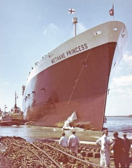
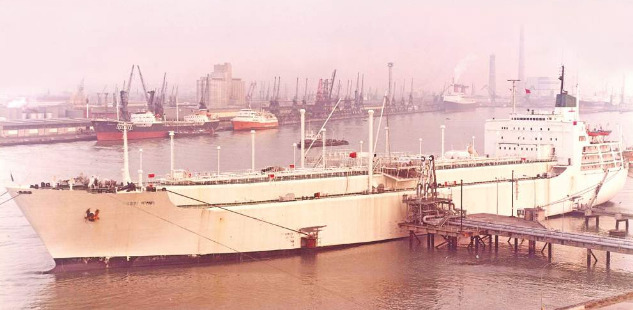
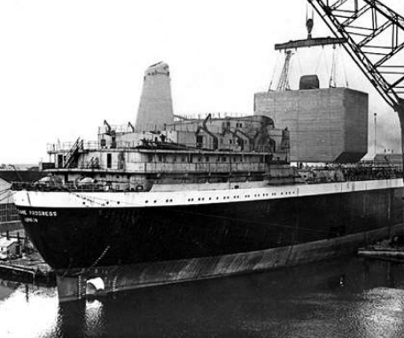
After launching his own ship design consultancy in 1946, James Henry had become a prominent figure in US marine circles as well as a leading innovator for a wide range of specialist cargo ships. Methane Princess and Methane Progress were also designed by JJ Henry, as was the first purpose-built, fully refrigerated LPG carrier. This was the 28 837 m3 Bridgestone Maru delivered from the Yokohama yard of Mitsubishi Nippon Heavy Industries in Japan in January 1962.
Also in the initial Methane Pioneer design team at JJ Henry were William duBarry Thomas, Alfred Schwendtner and Dick Eddy. The extensive knowledge of these pioneering gas ship naval architects was shared with the industry in later years through many notable presentations. Two which stand out are LNG carriers: The current state of the art by Thomas and Schwendtner and given to the Society of Naval Architects and Marine Engineers (SNAME) in 1971 and Whither the LNG ship? in 1974 by Thomas to the Royal Institution of Naval Architects (RINA).
Barry Thomas was also the compiler of SIGTTO’s much-missed LNG Log, an annual publication which recorded voyages completed by LNG carriers and was packed with the author’s delightful hands-on reminiscences. By the time Barry passed on the editor’s baton in the late 1990s LNG Log in its original format had become virtually unmanageable, such was the size of the matrix of LNGC voyages completed and the speed at which it was growing.
North Thames Gas Board in the UK had some key personnel overseeing the Pioneer Methane conversion. These included chief engineer James Burns, development engineer Leslie Clark and a young engineer, Denis Rooke, who later became Sir Denis and chairman of British Gas. Amongst his many appointments Sir Denis was one of the early GIIGNL vice-presidents.
In 1960 Shell joined Constock as a 40 percent shareholder and the company was renamed Conch International Methane. Continental Oil also owned a 40 percent stake in the new company and Union Stock Yard the remaining 20 percent. E. M. (Steve) Schlumberger, who had been seconded from Société Maritime Shell in Paris, was put in charge of the Conch R&D team. Steve was the engineer who introduced Gazocéan to refrigeration systems for LPG cargoes in 1955. Chuck Filstead, one of the original Constock engineers, was appointed technical director to oversee the design and construction of Methane Princess and Methane Progress, the first LNGCs to go into commercial service.
Conch also seconded senior naval architect Roger Ffooks from Shell International Marine to join this small design team. Roger became a key and well-respected spokesman for Conch throughout the 1960s and early 1970s, promoting the company’s containment systems based on the success of the two Methane ships.
During those early days Roger inevitably got caught up in the intense rivalry that existed between the promoters of the various pioneering LNGC containment systems, but he tended to be a calming influence. The protagonists came into the public spotlight at the regular Gastech and LNG series of conferences. The heated discussion periods, in which Roger would participate as a speaker or session chairman, have lived long in the memory of those present.
The ferocity of the various proponents’ sales pitches and criticisms of competing systems was balanced by Roger’s humour, poems, cartoons and thought-provoking responses. Many long-lasting friendships were born out of this rivalry. Roger’s classic book, Natural Gas by Sea, covers the early years of LNGC development with insight and authority.
As far back as 1954 Gaz de France, with Algerian gas in mind, had begun its own studies into the transport of LNG by ship. One of the company’s directors, Robert Labbé, was also a managing partner in the Worms Group. After a fact-finding visit to the US with Audy Gilles, Robert set up a research group called Methane Transport in 1959 to design a French LNG carrier. The experimental ship Beauvais and France’s first commercial LNG carrier, Jules Verne, were the tangible results from that group’s work.
There was a significant piece of equipment fitted onboard Beauvais. James Coolidge Carter of Costa Mesa in California provided a submerged electric motor pump (SEMP) for use in one of the vessel’s three cargo tanks. More than any other individual shipboard component, the JC Carter SEMP made the large-scale transportation of LNG by sea possible.
In July 1962 members of the Methane Transport research group, along with several others, were invited to a tank test in Oslo. The invitation was from shipowner ∅ivind Lorentzen and Texas-based investor Carol Bennett who wanted to demonstrate the viability of a membrane tank system based on an idea developed by Det Norske Veritas (DNV) engineer Bo Bengtsson. Attending, and impressed with the tests carried out using liquid nitrogen, were Pierre Verret from Gaz de France, Audy Gilles from the Worms Group and Jean Alleaume and Gilbert Massac from Gazocéan.
Following these observations, Gazocéan acquired the Norwegian patents and set about making substantial changes to the original design and registering new patents. In time, and through cooperation with Conch Océan, the Gazocéan membrane concept was to become the basis for the Technigaz Mark I containment system.
Conch Océan was established as a 60/40 Conch/Gazocéan joint venture in 1967 to enable the marriage of the Technigaz waffled stainless steel membrane with the Conch balsa wood insulation system. Amongst those on the design team taking out patents under the Conch Océan banner were Gilbert Massac, Michel Kotcharian and another ex-Shell man, Bob Jackson.
Going back to the evolution of the Gazocéan membrane itself, the next stage involved a seagoing trial. René Boudet, the company’s president, and his friend Carol Bennett agreed to build a small prototype ship to demonstrate the soundness of the design for LNG and to show that it could also be used for LPG and ethylene trading. Delivered in May 1964, the ship was the 630 m3 Pythagore.
René Boudet was one of the gas industry’s larger-than-life characters. A formidable pioneer of LPG trading and transport by sea in the 1950s, he founded Gazocéan in 1957. Following the success of the Pythagore prototype vessel, Boudet then placed a speculative order in 1968 for the 50 000 m3 Descartes, the first commercial ship with the Technigaz Mark I membrane. In 1979 René Boudet moved on from Gazocéan and created Geogas Enterprise, a Geneva-based LPG trading company.
One of the attendees at the Oslo test, Audy Gilles, had also been involved with the Beauvais project. The Worms Group man was investigating another potential membrane material. In particular he was considering a 36 percent nickel steel alloy which the Nobel prize-winning Swiss physicist Charles Édouard Guillaume had discovered in 1896 and named invar. Industrialised by Imphy Alloys of France, invar has a near-zero coefficient of thermal expansion.
The Worms Group put Pierre Jean in charge of a research team to look at invar in more detail and he was assisted by Pierre Legendre of Imphy. By October 1965 the researchers’ confidence in the material was sufficient for the Worms Group to establish Gaz Transport as a new subsidiary.
Six engineers joined president and founder Audy Gilles as the initial team members of Gaz Transport. Pierre Jean headed the group, which included naval architect Roger Lootvoet and Jacques Lenormand. Jacques Guilhem, who had been the engineer in charge of the Jules Verne project, also joined the team together with two other Jules Verne technicians, Michael Bourgeois and Jean-Pierre Morandi.
Work on the Moss LNG spherical tank containment system design started at Moss Verft in Norway in February 1969. Mikal Grønner, the president and CEO of Moss Rosenberg Verft (MRV), and his design team set off with a simple three-pronged strategy. The design had to provide a high standard of safety; the construction would have to be based on traditional shipbuilding methods; and the initial and operating costs of a spherical tank ship must be kept low.
The other members of the team were Hans Jorgen Frank, who joined MRV from the Lorentzen Group, Ragnar Bohgaes, the technical director of Moss Verft, and Olav Solberg, who was head of the steel structure department at Kverner Brug. The Kverner engineering group was the parent of MRV.
In early 1970 DNV was commissioned to help with the project and a team was assembled under the guidance of manager Rolf Kvamsdal. The society’s Per Tenge, Gunnar Wold and Odd Solli were directed to weigh up the choice of materials for the spherical tanks while Helge Ramstad examined stress levels and Odd Solumoen investigated insulation matters.
DNV president Egil Abrahamsen played an active role in this study, providing guidance on dealing with national and other regulatory bodies. Early on in the study James Howard, a former US Coast Guard officer, joined the Kverner Group and his background proved useful when dealing with the US maritime authorities. Later Tormod Grove and Hans Richard Hansen contributed extensively to the Moss spherical tank project with input on stress and fatigue analysis. In January 1971 Rolf Kvamsdal joined MRV as head of the gas technology department and quickly became the well-known front-man and publicist for Moss spheres.
After Methane Princess, Methane Progress and Jules Verne had established the initial Algeria-to-Europe LNG trade lanes, subsequent projects generated their own contributions to the pioneer pool. Esso’s DM Latimer played a key role in developing both the shipping and terminal elements for his company’s Libya venture while Alexander Delli Paoli was section head of Esso International’s tanker department and the man responsible for the design and construction of the four 41 000 m3 vessels built for the project.
Ed Torney, another naval architect from the JJ Henry stable, acted as design and construction advisor to Esso. He later joined Energy Transportation Corp, the company which operated the eight spherical tank ships on the Indonesia-Japan route on behalf of Burmah Oil.
The Alaska-Japan trade began in October 1970 and Phillips Petroleum’s vice-president LeRoy Culbertson and John Horn in the natural gas sales department were leading figures in getting the venture off the ground. RJ Wheeler, the company’s director of marine operations, headed the team responsible for the running of the two vessels that served the trade, Polar Alaska and Arctic Tokyo.
There were many other LNG shipping and terminal pioneers who did not grab as much limelight as those mentioned above. As SIGTTO and GIIGNL point out in their introductory remarks to this magazine, our industry owes a great deal of gratitude to all the pioneers that helped establish the solid foundation stones that are in place.
This group encompasses not just those who made the headlines but also those shipyard workers, welding experts, steel and aluminium manufacturers, insulation specialists, electrical engineers and cryogenic equipment suppliers who have played key but mostly unsung roles in logging 50 years of safe LNG operations.
In 2014, the shipping industry celebrated over 50 years of commercial LNG carrier operations. Whether you’re talking LNG carriers, LNG as a marine fuel, or LNG bunkering, our experience and leadership in the gas industry will help you make optimal decisions based on the best, independent technical expertise. Today’s decisions determine tomorrow’s performance.
European yards centre stage in LNG industry’s opening act
Although LNGC construction today is concentrated in the yards of Korea, Japan and China, they were not amongst the sector’s pioneering shipbuilders.
There was a great number of shipbuilders involved in the construction of the early LNG carriers. Some yards built only a single, albeit significant, vessel while others were involved with one or more series of ships, honing their skills with each delivery. As much of the LNG industry’s groundbreaking work was carried out in the UK, France and the US, and all three countries had both a strong shipbuilding tradition and growing demand for gas, it is not surprising that this trio of nations is responsible for many of the pioneering LNG carrier designs.
Politics also played a part. For example, Methane Princess, Methane Progress and Jules Verne, the first three LNGCs in commercial service, were required to be built in a home shipyard.
Vickers Armstrong (Shipbuilders) of Barrow-in-Furness in the northwest of England delivered the 27 400 m3 Methane Princess in June 1964. As the lead contractor on the project, the company also prepared the working drawings and placed material orders for the sistership Methane Progress, which was built at Harland and Wolff (H&W) of Belfast in Northern Ireland. However, the contract allowed the latter yard to follow some of its own building practices when constructing the conventional parts of Methane Progress.
Both ships featured nine aluminium alloy, prismatic cargo tanks of the Conch design. All drawings required approval from five separate organisations, namely Lloyd’s Register and American Bureau of Shipping as the dual classification societies, Conch, British Gas and Shell, which worked with J J Henry of New York on the vessels’ design.
Both ships were built on time and close to budget, although the first purpose-built LNGC for commercial service, Methane Princess, was to be the only gas ship built by Vickers. The yard, now BAE Systems, is still constructing sophisticated vessels, including nuclear-powered submarines and other complex naval ships.
H&W completed Methane Progress in July 1964. During work on the vessel the Belfast shipbuilder gained some experience with LNG membrane technology by building a prototype tank based on a Conch Methane Services idea. The membrane consisted of two sizes of rotating stainless steel trays supported by a balsa and plywood insulation system. The prototype was fitted inside a mild steel tank and installed on board the collier Findon. Towards the end of 1974 the tank was tested in service with cargoes of LNG, ethylene and liquid nitrogen. The test results were disappointing and the research work stopped.
In 1982 H&W completed and tested to destruction another prototype tank designed for the storage of gas liquids under pressure or at low temperature. This test tank was a one-third scale model of a multi-lobe tank design ordered by Motherwell Bridge Engineering and Ocean Phoenix Gas Transport of the Netherlands. The same year the yard delivered two 59 000 m3, fully refrigerated LPG carriers, Isomeria and Isocardia, for Shell. The pair were H&W’s only other involvement with Key Systems for LNG Carriers Containment and Safety: Design and Operationgas carriers.
In June 1962 Gaz Marine placed the contract for the 25 500 m3 Jules Verne at Ateliers et Chantiers de La Seine Maritime (ACSM) in Le Trait, France. Completed in March 1965, the ship had seven independent, vertically mounted, cylindrical cargo tanks of nine percent nickel steel. Two months later the ship discharged France’s first LNG cargo, a shipment from Algeria, at the newly commissioned Gaz de France import terminal at Le Havre.
Describing the Jules Verne’s cargo tanks as cylinders does not do justice to their ingenious shape. The lower bottom of each tank was an inverted cone with a rounded peak; the bottom at side was elliptical-toroid; and the top was ellipsoidal. Only the sides were cylindrical.
The design was selected from one of three different tanks which had been fitted on the 640 m3 converted experimental vessel Beauvais. The conversion had been completed in February 1962 by Chantiers de l’Atlantique at St Nazaire. Jules Verne was broken up in 2008 as Cinderella after a record-breaking 43 years in service.
Another experimental ship, the 630 m3 Pythagore, was completed by Ateliers et Chantiers du Havre (ACH) for Gazocéan in May 1964. The vessel was provided with two stainless steel membrane cargo tanks and this technology was to be the foundation of the Key Characteristics of Membrane Tanks SystemsTechnigaz membrane containment system. However, the matter was not settled until prolonged legal wrangling between Conch and Gazocéan over a number of patents was resolved. Pythagore carried two LNG cargoes and was then switched to trading in ethylene and LPG.
The ACH yard also delivered the 4 000 m3 Euclides, the first LNG carrier built with spherical cargo tanks, to Antarctic Gas, a Gazocéan subsidiary, in February 1971. Designed by Technigaz, the ship had four nine percent nickel steel cargo tanks. The ship’s maiden voyage was a stormy Atlantic crossing with a cargo of Algerian LNG for discharge at the Everett terminal in Boston, Massachusetts.
Kockums Mekaniska Verkstads in the Swedish port of Malmö constructed the first LNGC to the Gaz Transport membrane tank containment system design, with its distinctive invar primary and secondary barriers. The vessel, the 71 500 m3 Polar Alaska, was completed in August 1969 while sistership Arctic Tokyo followed in December of the same year. Both ships were employed carrying LNG on the first Pacific Ocean trade, from Kenai in Alaska to the Negishi terminal in Japan.
Kockums had already accumulated expertise with gas carrier construction, having completed the first fully refrigerated LPG carrier to be built in Europe, the 25 100 m3 Paul Endacott, in May 1964. Arctic Tokyo was built alongside another LPG carrier, the 26 500 m3 Phillips Arkansas, in the yard’s mammoth new building dock. The facility included a 140 m tall gantry crane with a lifting capacity of 1 500 tonnes.
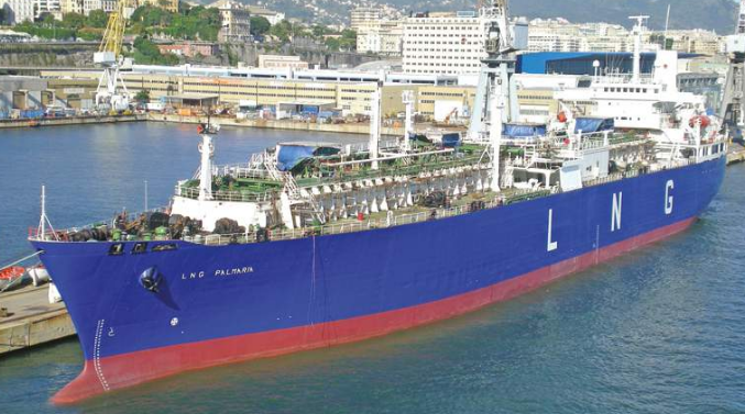
Italcantieri’s Genoa Sestri yard was the next to join the LNG shipbuilders’ club. Genoa Sestri completed a remarkable trio of 41 000 m3 ships for Esso International. These were Esso Brega, delivered in October 1969, Esso Portovenere in March 1970 and Esso Liguria in July 1970. A fourth, similar vessel, Laieta, was delivered to Esso in April 1970 from the Astano yard in El Ferrol. This was the first LNG carrier to be built in Spain.
Esso had developed its own independent cargo tank design for the four ships and commissioned the quartet to transport LNG from the new export terminal it had built in Marsa el Brega in Libya. Back in 1965 the energy major had signed a gas sale and purchase agreement covering the delivery of Libyan LNG to new receiving terminals at Barcelona in Spain and Panigaglia near La Spezia in Italy.
The four prismatic cargo tanks on each Esso ship were constructed with aluminium alloy and built by Chicago Bridge & Iron (CB&I). To avoid a Conch patent dispute, the tank vertical positioning keys were located at the centreline of the ship at the ends of the cargo tanks and at the mid-length at the sides. Sharing a joint lifetime service record with Jules Verne, Esso Brega was 43 when the ship was broken up in 2012 as LNG Palmaria.
The Heinrich Brand yard in Oldenburg, Germany, got in on the LNG carrier construction act in June 1971 when it delivered the 2 720 m3 Melrose to George Gibson of Leith in Scotland. This was the first of five ships from the shipbuilder for Gibson and Bernhard Schulte that were capable of carrying LNG cargoes. Although the ships never traded in LNG, they were the forerunner of today’s multipurpose LNG/ethylene carriers. At the time they were a notable achievement for both the shipyard and the vessels’ gas plant designer Liquid Gas Anlagen (LGA) of Rolandseck near Bonn.
Chantiers de l’Atlantique at St Nazaire achieved a major breakthrough with the completion of the 50 000 m3 Descartes for Gazocéan in September 1971. Able to transport both LNG and LPG, this was the first commercial size ship to be fitted with the Technigaz stainless steel membrane containment system.
The St Nazaire yard, now STX France, was not new to LNG technology, having supplied an aluminium tank surrounded by loose perlite insulation for the experimental ship Beauvais. Following Descartes the shipbuilder won a contract to construct four 75 000 m3 LNGCs for Shell for the Brunei-Japan trade. These Technigaz ships were delivered over the 1972–74 period.
Another French yard, Constructions Navales et Industrielles de la Méditerranée (CNIM) in La Seyne on the country’s Mediterranean coast, delivered its first LNG carrier, the 40 100 m3 Hassi R’Mel, in December 1971 to Compagnie Algérienne de Navigation (CNAN). As shareholders in Gaz Transport, the shipyard naturally chose the № 82 membrane containment system for the ship’s six cargo tanks.
CNIM had already acquired some valuable experience with membrane tank construction during the Gaz Transport system’s development phase. In December 1968 it had completed the 28 866 m3 prototype LPG carrier Hypolite-Worms, the tanks of which featured a single invar primary barrier.
Two months after CNIM completed Hassi R’Mel Chantiers Navals de la Ciotat, a rival of the neighbouring CNIM yard, handed over its first LNG carrier, the 40 000 m3 Tellier, to Messigaz. This five-tank ship had the Technigaz Mark I membrane containment system.
The first Moss spherical tank LNG carrier, the 88 000 m3 Norman Lady, entered into service in November 1973 on behalf of London-based owners Buries Markes and Höegh of Oslo. This distinctive ship was built at Moss Rosenberg Verft in the Norwegian port of Stavanger. One month later the 29 000 m3 Venator, also with spherical tanks, was delivered by the smaller yard Moss Verft in Moss, Norway, to Smedvigs Tankrederi of Stavanger.
By the mid-1970s the major rival LNG carrier Cargo Containment Systems of LPG and LNGcargo containment systems had been tested in service and the industry had proven the viability of each system. Today’s Q-flex and Q-max giants and the small-scale multigas carriers owe much to the tenacity of the entrepreneurs, innovative designers and shipbuilders of yesteryear. Bearing in mind the oil crises and other troubles of the time, these pioneers, in their wildest dreams, could not have predicted today’s LNGC fleet of over 400 ships and orderbook of 130-plus vessels.
Established LNGC containment systems fend off all comers
Despite the occasional announcements of proposed new LNGC containment systems, none has yet posed a serious threat to the established designs.
Today’s LNGC cargo containment systems are well established and proven in service. The developers of these systems had their ups and downs in the early days as they worked through steep learning curves to bring their technologies to maturity. The rivalry between them was intense and sometimes more time was spent on highlighting the weaknesses of competing systems rather than extolling the merits of the in-house product.
In truth there is something to be said for all the containment systems in use today. They would not have achieved the degree of acceptance they have if that was not the case. Each incorporates touches of technical brilliance, good engineering and innovative thinking throughout the supporting structures, materials and layouts that go to make up the system.
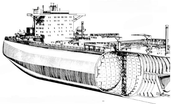
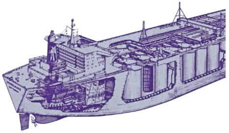
Early research and development work into how to carry a liquefied gas cargo at near atmospheric pressure and a temperature of -162 °C produced three basic approaches to LNG containment. One solution was the use of independent, self-supporting cargo tanks based on traditional shipbuilding techniques. Such tanks had internal webs and stiffeners and external insulation. Another offering was spherical tanks while perhaps the most radical was the use of a thin membrane supported by insulation and the hull structure.
Independent, self-supporting tanks were the first to get an airing. The converted, 5 000 m3 prototype vessel Methane Pioneer, the first ship to carry a seagoing cargo of LNG, in 1959, was provided with five aluminium alloy grade 5356–0 tanks. The insulation comprised prefabricated panels of balsa wood faced with maple and oak plywood fixed to the vessel’s hull. In 1962 the experimental ship Beauvais, fitted with three different types of independent cargo tank, was put through a series of tests off the coast of Brittany in France.
As a result of the Methane Pioneer and Beauvais trials, the first three commercial LNGCs were ordered. All had independent cargo tanks and all were constructed to transport Algerian LNG exports. The 27 400 m3 Methane Princess and Methane Progress were built in the UK to carry cargoes to the UK while the 25 500 m3 Jules Verne was built in France to handle French imports.
Each of the British pair had nine aluminium alloy 5083–0 prismatic tanks of the Conch design. These were insulated using glass fibre and plywood-faced balsa panels. The French ship had seven vertically mounted, cylindrical 9 percent nickel steel tanks. Each tank was supported on Klegecell insulation with loose perlite arranged around the sides and top.
The next newbuilding series, ordered in 1966, also sported independent, self-supporting tanks. The four 41 000 m3 vessels were built to carry Libyan exports to Italy and Spain on behalf of Esso. The vessels, each of which had four prismatic, aluminium alloy 5083–0 tanks, were built to the oil major’s own design. The insulation comprised a:
- layer of polyurethane foam (PUF);
- plywood sheets;
- a second layer of PUF;
- aluminium sheathing and aluminium batten strips.
The insulation arrangement was mounted on the outer tank boundary while the plywood was secured to the cargo tank with studs, and the aluminium batten strips fixed to the plywood with screws.
During the early 1960s French researchers had been promoting membrane technologies as technically and commercially sound solutions to the challenge of transporting liquefied gases by sea. Gaz Transport and Technigaz each developed such a membrane system and both were to go on and achieve great success with their respective technologies. Although the two companies merged in June 1994, in the early days they marketed their systems separately and competed fiercely for business.
In 1967 Gaz Transport signed a breakthrough commercial contract for the first application of its membrane tank containment system. The technology was chosen for Polar Alaska and Arctic Tokyo, a pair of 71 500 m3 vessels built by Kockums of Sweden for the pioneering Alaska-Japan trade.
Of major importance to the development of the Gaz Transport membrane system was the 28 700 m3 LPG carrier Hypolite-Worms. The Worms Group wanted to build a prototype ship to prove the viability of membrane technology to shipowners. The ship was ordered from Forges et Chantiers de la Méditerranée (FCM) in mid-1966, prior to the contracts for Polar Alaska and Arctic Tokyo, and was delivered in December 1968. In the same year FCM became Constructions Navales & Industrielles de la Méditerranée (CNIM).
On Hypolite-Worms a single, 0,5 mm thick invar membrane was fitted as the primary barrier, supported on a layer of plywood boxes filled with perlite insulation. The ship’s inner hull and cofferdams were constructed with low temperature steel to form the secondary barrier. A voyage from Ras Tanura to Tokyo Bay with a cargo of propane proved invar to be a suitable primary barrier material for the containment of liquefied gas cargoes.
Gaz Transport supplied its № 82 system for Polar Alaska and Arctic Tokyo. With this design both the primary and secondary barriers were constructed from invar, in this case 400 mm wide strips 0,5 mm thick. The strips had upturned edges and these were connected using automatic welding machines. The invar strips were set longitudinally in the holds of the two ships in a single length and secured at the ends.
The primary and secondary barrier thermal boxes had standard dimensions of 1,000 × 400 × 200 mm and were filled with perlite insulation. The insulating boxes, each of which weighed about 40 kg, were secured to the ship’s inner hull by a system of metal and wood support beams.
A total of 10 ships were constructed with the Gaz Transport № 82 system, including the 40 000 m3 Hassi R’Mel and the 125 000 m3 El Paso Paul Kayser.
In the early 1960s Technigaz bought the rights to the membrane patent taken out by Bo Bengtsson of Det Norske Veritas (DNV) in Norway. In May 1964 the 630 m3 experimental ship Pythagore was delivered to Gazocéan by Ateliers et Chantiers du Havre (ACH). This ship was fitted with two stainless steel membrane cargo tanks of the Technigaz Mark I type. The trials established the design as suitable for the carriage of LNG.
Read also: Methane Pioneer Achievement – Revolutionizing Energy and Combating Climate Change
The first commercial ship to be ordered with the Technigaz stainless steel membrane was the 50 000 m3 Descartes, completed in September 1971. The vessel was ordered by Gazocéan speculatively in order to prove the viability of the Technigaz Mark I membrane system on a commercial-scale vessel. The newbuilding contract went to Chantiers de l’Atlantique at St Nazaire.
The primary barrier membrane of the Mark I system comprised 1,2 mm thick sheets of 304L stainless steel. The pieces were corrugated in two directions to allow for thermal contraction and expansion. The primary barrier was supported by balsa wood blocks. The secondary barrier consisted of a layer of sugar maple plywood supported on three layers of balsa wood.
The 4 000 m3 Euclides was the first LNG carrier built with spherical cargo tanks and the first without a secondary barrier. The system was also a Technigaz design and the vessel, like Pythagore, was built by ACH. The ship had four 9 percent nickel steel cargo tanks cunningly hung from the main deck and was delivered to Gazocéan in February 1971.
The Moss LNG spherical tank design was to dominate the LNGC market during the 1970s and 1980s. Work on that concept started at Moss Verft in Norway in February 1969. Norwegian shipowner Leif Höegh was interested in exploring opportunities in LNG transport and had presented the Moss yard with an outline specification for a membrane LNGC for its opinion. Moss studied that and also some spherical tank options. At that point Moss decided that spherical tanks offered the optimum solution and that it would develop its own design for such tanks.
One of the aims of the Moss team examining the alternatives then in service was to come up with an approach that obviated the need for an expensive secondary barrier and was suitable for use on large vessels. They were able to achieve this by looking at a pressure vessel type of tank to see if the applicable stress analysis and non-destructive material and welding tests could be used as a basis for an LNG cargo tank design.
Moss was fortunate that DNV and other researchers in Norway were at the forefront of finite element and fracture mechanics stress analysis. These parties between them were able to produce what came to be known as the «leak before failure» concept for spherical cargo tanks supported by an equatorial ring. This simple, stress-determinate structural design does not require the traditional secondary barrier found on other gas carriers. Instead there is a leak protection system consisting of a drip tray under the tank and splash shields up to a suitable height around the tank.
The first ship fitted with Moss spherical tanks was the 88 000 m3 Norman Lady, delivered by the affiliate yard of Moss Rosenburg Verft in Stavanger to a Lief Höegh/Buries Markes joint venture in November 1973. The ship’s five 9 percent nickel steel tanks had a polystyrene spiral-wound insulation system developed by Teknisk Isolering.
Two months later the 29 000 m3 Moss spherical tank Venator was delivered to Peder Smedvig from the smaller Moss Verft. The vessel’s four aluminium alloy tanks were insulated using a panel system developed by Kaefer.
The membrane and Moss spherical tank concepts have remained generally unchallenged in the intervening years. While invar strips and plywood boxes have increased in size, secondary barriers have been tweaked and tank dimensions and diameters have been boosted, no serious contender has emerged to offer competition to these pioneering French and Norwegian designs.